 2018, Vol. 29


b Shenzhen Key Laboratory for Minimal Invasive Medical Technologies, Institute of Optical Imaging and Sensing, Graduate School at Shenzhen, Tsinghua University, Shenzhen 518005, China;
c Center for Precision Medicine and Healthcare, Tsinghua-Berkeley Shenzhen Institute, Tsinghua University, Shenzhen 518055, China;
d Department of Physics, Tsinghua University, Beijing 100084, China
The ultrafine fibers prepared by electro-spinning method have been widely used in the fields of filtering materials, composite reinforcing materials, and biomedicine [1, 2]. This method can help us to produce fiber with porous morphology quickly and efficiently, which will greatly promote its application in these above-mentioned fields [3]. Scanning electron microscopy (SEM) is often used to observe the microstructure of fiber materials, but the disadvantages of this method are high cost and timeconsuming, therefore, it is very urgent to find a method that can quickly distinguish different morphologies [4-7]. It has been known that optical techniques based on polarized photon scattering are sensitive to the microstructure of complex biological tissues [8-11]. Considering this, we obtained a large number of ultra-fine fibers with different morphologies, such as beaded surface, smooth surface and microporous through electro-spinning technology and binary blending method [12]. Then we made comparison analysis on these different fibers using both the electron microscopy and Mueller matrix which represents the comprehensive polarization properties of the samples [13-15]. The result showed that the depolarization parameter MMD-Δ from the Mueller matrix decomposition is very sensitive to the surface mesh and beading, providing an effective method for quickly differentiating the different microstructures of electro-spun fibers.
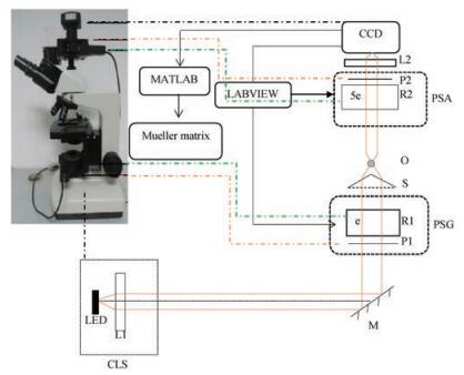
Scanning electron microscope (SEM, S3400 N), provided by School of Materials Science and Engineering, Sichuan University. Polarized light microscope, 1/4 wave plate, polarizer (Wuhan You Guang Technology Co., Ltd., labview 2014), CCD (qimaging, q42720), Sorabot motors, provided by Shenzhen Key Laboratory for Minimal Invasive Medical Technologies, Institute of Optical Imaging and Sensing. PLLA (Mw: 100000, provided by Chengdu Hang Feng Chemical Reagent Co.). PCL (Mw: 50000, provided by Chengdu Hang Feng Chemical Reagent Co.). DMF (N, N-dimethylformamide, Mr: 73.09, Ar, provided by Chengdu Chang Liao Chemical Reagent Company). CH2Cl2 (Mr: 84.93, Ar, provided by Chengdu Chang Liao Chemical Reagent Co.). Fig. 1 is a schematic of a polarized light microscope.

|
Download:
|
| Fig. 1. The schematic diagram of polarization microscope. CLS, monochromatic light source; P1 and P2, polarizers; R1 and R2, quarter-wave plates; L1 and L2, lenses; O, 4×, 10×, 20×, 40× objectives. | |
The PLLA and PCL were mixed in different proportions and dissolved in methylene chloride. After a certain amount of DMF was added, a spinning solution of 4 wt%-8 wt% was prepared. After the above-mentioned solution was sealed, the solution was stirred at room temperature for 4 h and 30 mL of it was taken out as an electro-spinning solution. The electro-spinning parameters are as follows. The voltage: 15 kV; the receiving roller speed: 100 r/min; the injection propulsion rate: 10 mL/h; the receiving distance: 15 cm; the temperature: 15 ℃, the humidity: 45%, the spinning time: 30 min [16]. The following Table 1 is the main process of the electro-spun fiber we have prepare.
|
|
Table 1 Main process of different fibers. |

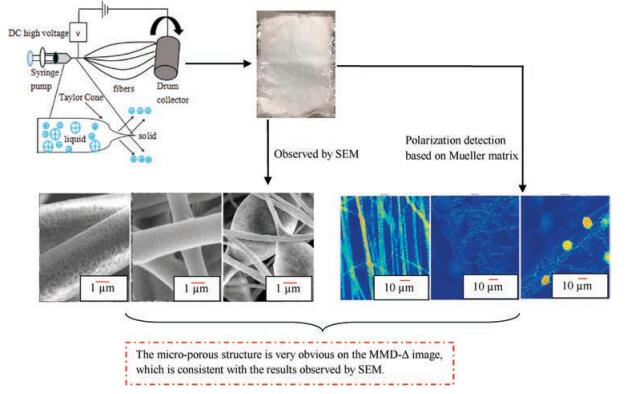
The SEM was used to observe the fiber morphology of different components at 5 kV and the fiber was imaged with a polarizing microscope. The total magnification was ×400, the exposure time was 9000 μs, and it was corrected by the air. Fig. 2 shows the fiber preparation and characterization in this experiment.

|
Download:
|
| Fig. 2. Preparation and testing results of electrospun fibers. | |
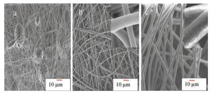
The electro-spun fibers prepared under different ratios have completely different morphologies [17-19]. The surface of the fiber in Fig. 3a is smooth and its diameter is about 0.67 μm. A large number of beaded microspheres appear, and the surface of the microspheres has many micro-porous openings. In Fig. 3b, the surface of the fiber is smooth and this fiber is regular in appearance, with a diameter of about 1.86 μm. The fiber in Fig. 3c is very orderly, with a diameter of about 4.29 μm, a large number of micro-porous on the surface of the fiber, and a microporou diameter of about 300 nm. These three completely different fibers basically represent the morphology of common fibers. The purpose of preparing these three types of fibers are to prepare for the rapid detection of polarized light.

|
Download:
|
| Fig. 3. SEM of different morphology electrospun fibers(a: 6 wt% PLA/PCL(25:75);b: 8 wt% PLA/PCL (50:50). c: 6 wt% PLA). | |
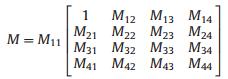
Although Mueller matrix contain all the polarization properties of a sample, its 16 elements luck explicit connections to the characteristic or optical properties. Mueller matrix decomposition (MMD) proposed by Shih-yau Lu and Russell A. Chipman [20] can decompose a Mueller matrix into parameters of clear physics meanings, such as: dichroism (polarization-dependent intensity attenuation properties), phase retardation (polarization-dependent phase change properties), depolarization (conversion capability from polarized light to unpolarized light). This MMD parameters represent more explicit polarization characteristics of the medium. In this paper, we characterize the irregular structure of the fiber surface using the depolarization parameter MMD-Δ, which has been found sensitive to the Rayleigh scattering components in turbid media [21, 22].
The polarization decomposition expression of Muller matrix is as follows:
|
(1) |
Dichroism is defined as:
|
(2) |
Scattering deflection is:
|
(3) |
The obtained three sub-matrices are:
|
(4) |
Sample depolarization matrix to incident light:
|
(5) |
Sample phase delay matrix to incident light:
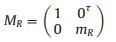
|
(6) |
Sample amplitude bidirectional attenuation matrix to incident light:
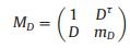
|
(7) |
m:——3 × 3 submatrix of each standard matrix.
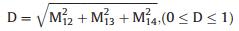
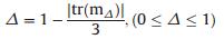
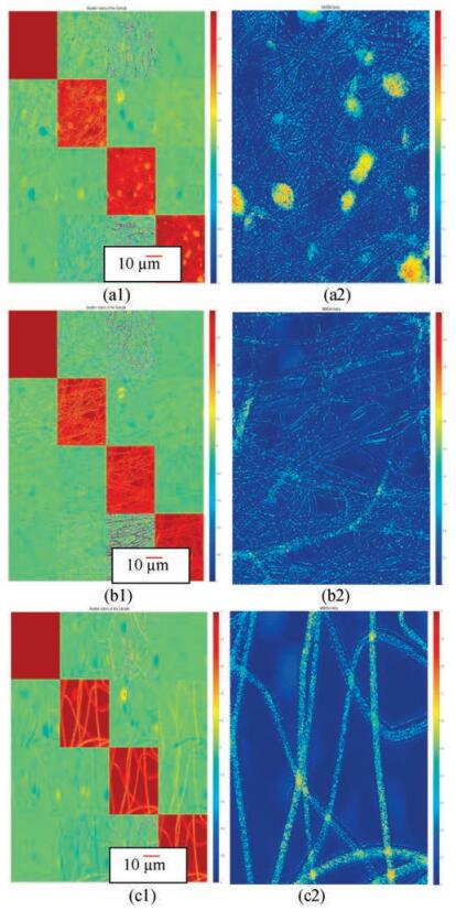
Fig. 4 are Mueller matrix image (left) and its MMD-Δ parameter diagram (right) for three differently shaped samples. The depolarization parameter from the Mueller matrix decomposition, MMD-Δ, represents the degree of depolariza-tion due to scattering of the irregular structures, which is shown in Fig. 4 as the normalized color bar varying 1-0. It is shown in Fig. 4, when a large number of sieve holes or microspheres appear on the fiber surface, the Mueller matrix diagonal elements m22, m33 and m44 show higher brightness, indicating bigger depolarization [23]. Corresponding to the three different morphologies in Fig. 4, MMD-Δ shows distinct values: for Fig. 4a2, the beaded microspheres are more irregular than the fiber itself, and there are a large number of micro-porous, the depolarization value is larger, as shown by the more reddish color; the surface of the fiber in Fig. 4b2 is smooth with no meshes, the overall depolarization value is smaller, as show by the blue; for Fig. 4c2, there are a lot of irregular micro-pores on the surface of the fiber, the image is more reddish and the depolarization value is also higher. From the Mueller matrix diagonal elements, it can also be seen that the surface of the fiber with irregular structure has a higher value, or more significant depolarization.

|
Download:
|
| Fig. 4. MMD-Δ parameter and Mueller matrix diagram of electrospinning fibers with different morphologies (a: 6 wt% PLA/PCL (25:75); b: 8 wt% PLA/PCL (50:50); c: 8 wt% PLA). | |
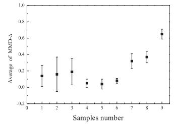
Fig. 5 shows average MMD-Δ parameters of all samples in this experiment. It is easy to see that the MMD-Δ parameters of fibers with different morphologies vary significantly. Combining with Fig. 5, it is found that this method is simple and reliable, and it is a fast, non-destructive, reliable and effective means of detecting different surface morphologies of electro-spun fibers.

|
Download:
|
| Fig. 5. Average MMD-Δ parameters of all samples. | |
Rapidly differentiating electro-spun fibers with different morphologies can not only improve the electro-spinning preparation technology, but also greatly reduce the time and cost of microscopic morphology detection. In this paper, SEM and polarization detection based on Mueller matrix are performed for the three most common electro-spun fibers with different morphologies. The result shows that the parameter MMD-Δ is extremely sensitive to the surface of fibers, and the average numerical performance is very reliable. It is a method on rapid detection of different microscopic morphology of electro-spun fibers, providing an effective technique for rapid screening of electro-spun fibers. However, the structural information represented by the Muller matrix is very complex, And this method is not suitable for fibers less than 400 nm in diameter. More efforts need to be made subsequently on the issue whether other parameters can be used for different shapes and even whether different components of fibers can be distinguished.
AcknowledgmentThanks for standing in this article by Shenzhen Key Laboratory for Minimal Invasive Medical Technologies, Institute of Optical Imaging and Sensing.
| [1] |
N. Bhardwaj, S.C. Kundu, Biotechnol. Adv. 28 (2010) 325-347. DOI:10.1016/j.biotechadv.2010.01.004 |
| [2] |
D.H. Reneker, A.L. Yarin, Polym. J. 49 (2008) 2389-2411. |
| [3] |
J. Weiss, Crit. Rev. Food Sci. Nut. 15 (2011) 776-792. |
| [4] |
X.M. Liu, D.Q. He, K.J. Fang, Chin. Chem. Lett. 26 (2015) 1174-1178. DOI:10.1016/j.cclet.2015.05.006 |
| [5] |
S.H. Shen, S.J. Deng, Y. Zhong, et al., Chin. Chem. Lett. 27 (2017) 2219-2222. |
| [6] |
D. Jiang, X. Zhang, D. Yu, et al., J. Biomed. Nano 13 (2017) 243-254. DOI:10.1166/jbn.2017.2346 |
| [7] |
P. Chen, T. Aso, R. Sasaki, et al., J. Biomed. Nano 13 (2017) 324-336. DOI:10.1166/jbn.2017.2335 |
| [8] |
N. Ghosh, I.A. Vitkin, J. Biomed. Opt. 16 (2011) 110801. DOI:10.1117/1.3652896 |
| [9] |
B. Kunnen, C. Macdonald, A. Doronin, et al., J. Biophot. 8 (2015) 317-323. DOI:10.1002/jbio.v8.4 |
| [10] |
X. Cui, A.L. Rohl, A. Shtukenberg, B. Kahr, J. Am. Chem. Soc. 135 (2013) 3395-3398. DOI:10.1021/ja400833r |
| [11] |
R.S. Gurjar, V. Bacman, L.T. Perelman, et al., J. Nat. Med. 7 (2001) 1245-1248. DOI:10.1038/nm1101-1245 |
| [12] |
B. Avinash, Y.W. Mai, S.C. Wong, et al., J. Compos. Sci. Technol. 70 (2010) 703-712. DOI:10.1016/j.compscitech.2010.01.010 |
| [13] |
S. Alali, I.A. Vitkin, J. Biomed. Opt. 20 (2015) 061104. DOI:10.1117/1.JBO.20.6.061104 |
| [14] |
M. Villiger, D. Lorenser, R.A. Mclaughlin, et al., J. Sci. Rep. 6 (2016) 28771. DOI:10.1038/srep28771 |
| [15] |
C. He, H. He, J. Chang, et al., J. Biomed. Opt. Express 6 (2015) 2934-2945. DOI:10.1364/BOE.6.002934 |
| [16] |
D.G. Yu, J.M. Yang, L. Li, P. Lu, L.M. Zhu, J. Fib. Polym. 13 (2012) 450-455. DOI:10.1007/s12221-012-0450-z |
| [17] |
Q. Yang, T. Sun, J.Y. Yu, J.X. Ma, Chin. Chem. Lett. 27 (2016) 412-416. DOI:10.1016/j.cclet.2015.12.025 |
| [18] |
J.J. Liang, M.G. Zhao, L.J. Ding, S.S. Fan, S.G. Chen, Chin. Chem. Lett. 28 (2017) 670-674. DOI:10.1016/j.cclet.2016.10.035 |
| [19] |
S.J. Guo, J. Bai, H.O. Liang, C.P. Li, Chin. Chem. Lett. 27 (2016) 459-463. DOI:10.1016/j.cclet.2015.12.029 |
| [20] |
S.Y. Lu, R.A. Chipman, J. Opt. Soc. Am. A 13 (1996) 1106-1113. DOI:10.1364/JOSAA.13.001106 |
| [21] |
R. Liao, N. Zeng, X. Jiang, et al., Biomed. Opt. 15 (2010) 036014. DOI:10.1117/1.3442730 |
| [22] |
E. Du, H. He, N. Zeng, et al., J. Biomed. Opt. 19 (2014) 76013. DOI:10.1117/1.JBO.19.7.076013 |
| [23] |
D. Chen, N. Zeng, Q. Xie, et al., Biomed. Opt. Express 8 (2017) 3559-3570. DOI:10.1364/BOE.8.003559 |