 2018, Vol. 29


b Collaborative Innovation Center of Chemical Science and Engineering(Tianjin), Tianjin University, Tianjin 300072, China
Silicas with different morphologies, especially hollow silica spheres and hollow silica tubes, have attracted much attention in many fields such as drug delivery, catalysis, adsorption, bioseparation [1] due to their hollow structures and special properties. Template method is the common method for morphologycontrolled synthesis of porous materials. The templates can be classified into two categories including hard templates and soft templates. Hard template methods are often used to synthesize hollow silica spheres and hollow silica tubes with uniform structure and simple synthetic method [2, 3]. The polymer latex particles, inorganic and metallic oxide can be used as hard templates for the synthesis of hollow silica [4]. However, complicated technology, low production and low intensity seriously restrict the development of hard templates [5]. Compared to hard template method, soft template method is relatively simple and effective, especially the templates are easily obtained and removed. Up to now, hollow silica spheres have been synthesized with cross-linked polystyrene (PS) microspheres as hard template [6]. Emulsion droplets such as polymeric micelles [4], ionic liquid microemulsion droplets [7], or water-in-oil type (W/O) macroemulsion as soft templates [8], melamine formaldehyde (MF) microspheres as sacrificial template [9] and even template-free method [10]. Similarly, silica tubes have been synthesized with nanoporous anodic aluminum oxide (AAO) [11, 12], polystyrene fibres [13] and carbon nanotubes [14] as hard template or surfactants as soft templates [15-17], or template-free method [18]. In a type of soft-templating approach, silica with different morphologies can also be synthesized with various dual templates containing amphiphilic molecules such as two different ionic surfactants [19], an ionic copolymer and an ionic surfactant [20], and a non-ionic copolymer and an ionic surfactant [21, 22].
Ionic liquids (ILs) have caused much attention in many fields based on their prominent properties such as extremely low volatility, good thermal stability and designable structure [23]. Most recently, ILs have been introduced as soft templates to synthesize various materials including silver nanowires, CuO nanoplates and mesoporous γ-Al2O3 [24-26]. On one hand, ILs have extended ordering of nanostructure because they can form extended hydrogen bonds in the liquid state [27]. Therefore, ILs can be considered as good candidates for the templates to synthesize the nanostructured inorganic materials [28, 29]. On the other hand, imidazolium ionic liquids show amphipathy with hydrophilic imidazole ring head group and hydrophobic longish alkyl chain similar to surfactants [30, 31]. Many researches also indicated that imidazolium-based ionic liquids could form liquid crystalline phase in aqueous solution just like surfactants [32, 33]. As a result, long alkyl chain imidazolium-based ILs and surfactants have been used as co-template to synthesize inorganic materials such as hollow silica spheres [34]. But so far, vesicle formation and co-π–π stack mechanism are usually to explain the formation of inorganic materials with various morphologies. No report has involved synthesis of silica tubes using ILs and surfactants as co-template with sol-gel method.
Herein, we present a novel sol-gel method to synthesize silica hollow spheres and tubes with disordered or ordered mesopores by using an ionic liquid 1-decyl-3-methylimidazolium chloride ([Dmim]Cl) and a nonionic surfactant P123 (PEO20PPO70PEO20) as the template or co-template. The micelles co-assembly mechanism is supposed to be responsible for the formation of the silica morphology and mesostructure.
In our experiments, tetraethyl orthosilicate (TEOS) and hydrochloric acid (36–38 wt%) were acquired from Tianjin Guangfu Chemical Reagents. P123 (PEO20PPO70PEO20) was purchased from Sigma-Aldrich. [Dmim]Cl was purchased from Lanzhou Institute of Chemical Physics, Chinese Academy of Sciences (LICP, CAS). All the chemicals were used as received without further purification. And the mesoporous silica was synthesized using TEOS as the precursor, ionic liquid [Dmim]Cl and surfactant P123 as the templates via the sol-gel method. The molar ratio of P123/[Dmim] Cl varied in the range of 0-0.09. The chemical structure of [Dmim]Cl and surfactant P123 are shown in Scheme 1.

|
Download:
|
| Scheme 1. Chemical structures of [Dmim]Cl and P123. | |
In a typical synthesis, 2.60 g P123 and 3.87 g [Dmim]Cl were dissolved in 50 mL water, followed by adding 1.70 g 37 wt% hydrochloric acid and 2.40 g TEOS under stirring. After being stirred for 24 h at 40 ℃, the mixed solution was sealed to undergo aging and gelation. After aging for 24 h at 90 ℃, the formed gel was filtered and washed with water for three times to remove the templates. Afterwards the white solid was dried at ambient temperature overnight and then calcined at 600 ℃ for 6 h with a heating rate of 2 ℃/min to obtain SiO2. All the experiment conditions are listed in Table 1.
|
|
Table 1 Morphology and pore parameters of the calcined silicas with different P123/[Dmim]Cl molar ratios. |

The nitrogen adsorption and desorption isotherms at -196 ℃ were performed on an ASAP analyzer (Tristar3000, Micromeritics, U.S.A.). Morphology observations were performed by scanning electronic microscopy (SEM, Nanosem 430, FEI, U.S.A.) and transmission electronic microscopy (TEM, JEM-2100F, Japan). The silicas were characterized by X-ray diffraction (XRD, Philips X' pert, Cu Kα radiation k = 1.54056 Å, U.S.A.) in the 2θ range of 0.5–8°. TGA experiments (Du Pont Instruments 951 thermogravimetric analyzer, Netzsch, Germany) were performed on a 10 mg sample from room temperature to 800 ℃ in flowing air at a heating rate of 10 ℃/min. FTIR spectra of the samples (KBr pellets) were recorded at room temperature on a VECTOR-22 (Bruker, Germany) spectrometer within the range 400–4000 cm-1.
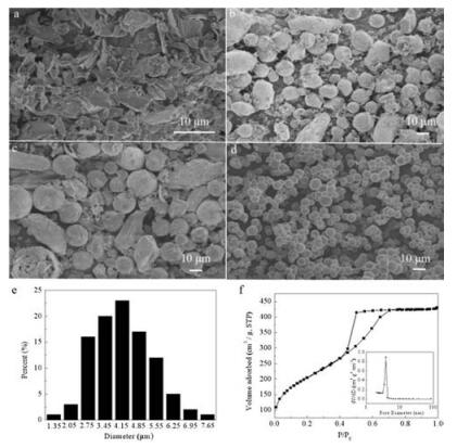
SEM images in Fig. 1 shows the morphology evolution of silica by using IL alone with different dosage of [Dmim]Cl. When the dosage of [Dmim]Cl is low, flake-like silica (Fig. 1a) can be prepared. And then the silica hollow spheres begin to appear when the dosage of [Dmim]Cl increases to 0.005 mol, with bulk-like silica (Figs. 1b and c). It can also be observed in sample A3 in Fig. 1c that there exist some incomplete spheres with hollow structure, illustrating that [Dmim]Cl starts to lead the formation of the silica hollow spheres. The hollow spheres become uniform with the mean diameter of 4 μm (Fig. 1d) when the amount of [Dmim]Cl reaches up to 0.015 mol. The TEM image of sample A4 can be seen in the inset of Fig. 1d. And the size distribution histogram of sample A4 is shown in Fig. 1e which further exhibits the detailed size of the silica spheres. These results suggest that ionic liquid [Dmim]Cl plays an important role in the formation of silica hollow spheres. N2 adsorption and desorption isotherms and the inset pore size distributions of the synthesized silica are shown in Fig. 1f. It shows that SiO2 hollow spheres (sample A4) have a Ⅳ type N2 adsorption and desorption isotherm with a distinct H2 hysteresis loop in the range of 0.4-1.0 P/P0, indicating that the synthesized silica hollow spheres have ink bottle mesopores. Moreover, the pore parameters of mesoporous silica synthesized with only ionic liquid as the template (samples A1-A4) are reported in Table 1. The hollow silica spheres with uniform diameters (sample A4) have the specific surface area of 750 m2/g and the mean pore size of 3.5 nm.

|
Download:
|
| Fig. 1. SEM images of the calcined sample A1 (a), sample A2 (b), sample A3 (c), sample A4 (d) with different [Dmim]Cl dosages and TEM image of sample A4 with hollow structure (inset), particle size statistical chart of sample A4 (e), N2 adsorption and desorption isotherm (f) and the pore size distribution curve (inset) of sample A4. | |
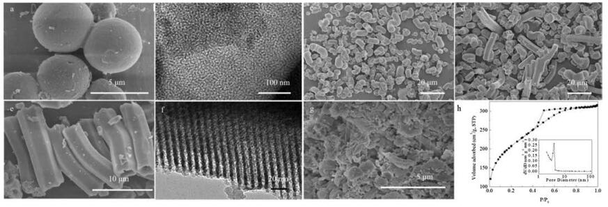
The morphology evolution of silica with different molar ratios of P123 to [Dmim]Cl via co-template method is shown in Fig. 2. When the molar ratio of P123 to [Dmim]Cl is 0.03, silica spheres with the diameter of 5 μm are synthesized as shown in Fig. 2a. Different from the dispersive spheres synthesized with only [Dmim]Cl, the silica spheres here adhere to each other tightly, which means that the addition of P123 may strengthen the binding force between spheres. When the molar ratio of P123 to [Dmim]Cl increases to 0.04, a large portion of silica spheres gradually develop into curved silica tubes in Fig. 2c, accompanied with the hollow spheres due to the inadequate amount of P123. With the further increase in the molar ratio of P123 to [Dmim]Cl, the silica tubes become longer and prism morphology begins to appear in Fig. 2d. With the molar ratio of P123 to [Dmim]Cl up to 0.09, the silica tubes became uniform and spheres disappeared completely (Fig. 2e). The SEM image of sample B4 in Fig. 2e indicates that the prism-like silica tubes with the length of ~15 μm, outer diameter of ~3 μm and inner diameter of ~2 μm have been prepared with [Dmim]Cl-P123 co-template. Bulk silica without any tubes was comparatively synthesized by using P123 alone, shown in Fig. 2g. It indicates that both P123 and [Dmim]Cl have significant effects on the morphology of silica tubes. The TEM image of Fig. 2b presents wormlike mesopores of silica spheres and the TEM image of Fig. 2f shows ordered mesoporous silica tubes wall. N2 adsorption and desorption isotherms and the pore size distributions of the synthesized silica are shown in Fig. 2h. The SiO2 tubes (sample B4) have a Ⅳ type N2 adsorption and desorption isotherm with a distinct H2 hysteresis loop above in the range of 0.4-1.0 P/P0, assigned to ink bottle mesopores. Pore size distributions of sample A4 and B4 (the insets of Figs. 1f and 2h), derived from the adsorption branch of the isotherm by Barrett-JoynerHalenda(BJH) model, are both centered around 4 nm, which further confirm that the mesoporous silica are formed. The pore parameters of mesoporous silica synthesized with [Dmim]Cl-P123 co-template (Samples B1–B4) are listed in Table 1. It shows that the prism-like silica tubes (Sample B4) have the specific surface area of 873 m2/g and the mean pore size of 3.6 nm. Fig. 3 shows the X-ray patterns of sample B4 and sample A4. Sample B4 shows one intense peak (100) associated with well-ordered hexagonal symmetry of channel structure. Sample A4 only shows one broad peak, indicating the existence not ordered mesopores. The XRD result corresponds with the TEM observation.

|
Download:
|
| Fig. 2. SEM images of the calcined sample B1 (a), sample B2 (c), sample B3 (d), sample B4 (e) with the co-template at different P123/[Dmim]Cl molar ratios and sample C1 (g) with only P123 as the template, TEM images of wormlike mesopores of silica spheres (b) and ordered mesopores for silica tubes (f), N2 adsorption and desorption isotherm (h) and the pore size distribution curve (inset) of sample B4. | |

|
Download:
|
| Fig. 3. XRD pattern of sample A4 and sample B4. | |
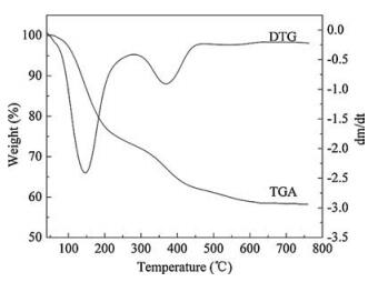
The curves of TGA and DTG analyses of as-synthesized silica with [Dmim]Cl-P123 co-template are presented in Fig. 4. From Fig. 4, the weight loss of 1.3% below 100 ℃ can be attributed to the evaporation of the physically adsorbed water. The significant weight loss of 25.6% from 100 ℃ to 300 ℃ should be due to the weight loss of the hydroxyl groups in the crystalline structure and the removal of the organic templates including [Dmim]Cl and P123. Another weight loss of 11.2% from 300 ℃ to 450 ℃ is caused by the complete removal of the residual organic templates. The weight loss above 450 ℃ is ascribed to the loss of water via condensation of silanol groups in the silica framework. No changes in the TGA curve can be observed over 600 ℃. These results demonstrate that [Dmim]Cl and P123 can be fully removed under the calcination temperature.

|
Download:
|
| Fig. 4. TGA-DTG curves of as-synthesized silica tubes with co-template of P123 and [Dmim]Cl. | |
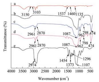
The FT-IR spectra of pure P123, [Dmim]Cl, as-synthesized silicas with [Dmim]Cl template and [Dmim]Cl-P123 co-template are respectively shown in Fig. 5. Curve a shows that the FI-IR spectrum of pure [Dmim]Cl. Peaks at 3150 cm-1 and 3103 cm-1 are ascribed to the non-symmetric stretching vibrations of imidazole ring of [Dmim]Cl, while the peaks centered around 1537 cm-1 and 1460 cm-1 correspond to the symmetric stretching vibrations of imidazole ring. The peak at 1135 cm-1 belongs to the C-H stretching vibration of imidazole ring. Peaks at 2961 cm-1 and 2870 cm-1 are attributed to the C-H stretching vibration of alkyl chain. For the FT-IR spectra of the synthesized silicas in Fig. 5 (curves c and d): (ⅰ) broad peaks around 1087 cm-1 and 798 cm-1 are assigned to the non-symmetric and symmetric stretching vibrations of Si-O-Si respectively; (ⅱ) peak at 474 cm-1 belongs to O-Si-O vibrations from bridge bending modes; (ⅲ) peak at 962 cm-1 corresponds to the Si-OH stretching vibrations. Because of the interaction between [Dmim]Cl and silanol, the peaks ascribed to the stretching vibrations of imidazole ring become broad and weak and shift to lower wavenumbers. It should be attributed to the decrease of electron density of C-H bonds of the rings based on the π–π stacking interaction of the positivecharged imidazolium-rings and the hydrogen bond between the anion of [Dmim]Cl and hydroxy group of silanol [35]. The peaks of alkyl chain C-H stretching vibration and the symmetric stretching vibrations of imidazole ring both become weaker, which is caused by the π–π stacking interaction of imidazolium-rings. The FT-IR spectrum of pure P123 is shown in Fig. 5 (curve e), The peaks at 2974 cm-1, 1454 cm-1, 1373 cm-1, 1296 cm-1 belong to the nonsymmetric and symmetric stretching vibrations of C-H, while peak around 1107 cm-1 is ascribed to the non-symmetric stretching vibrations of C-O-C. The peaks of the non-symmetric stretching vibrations of C-O-C shift to 1083 cm-1 and become weaker in Fig. 5 (curves c and d), which is attributed to the formation of hydrogen bond between P123 and silanol. After calcined at 600 ℃, all the peaks related to P123 and [Dmim]Cl are disappeared and the vibrations of Si-O-Si and Si-OH are prominent as shown in Fig. 5 (curve b).

|
Download:
|
| Fig. 5. FT-IR spectra of pure [Dmim] Cl (a), sample B4 after calcination (b), assynthesized samples sample B4 (c), as-synthesized sample A4 (d) and pure P123 (e). | |
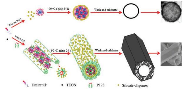
We now propose a possible mechanism on the formation of the hollow silica spheres or silica tubes illustrated in Scheme 2. During the synthesis, TEOS as the precursor hydrolyzes fast while the hydrolysate condenses slowly in acidic environment by adjusting the pH of the solution with HCl. As a result, stable small oligomers Si(OC2H5)4-x(OH)x are formed. In the meantime, when the concentration of [Dmim]Cl is higher than the critical micelle concentration (0.062 mol/L, 298 K) [36], the IL [Dmim]Cl selfassembled into sphere-like micelles due to the formation of the hydrogen bonded network and π–π stacking interactions. Herein oligomers Si(OC2H5)4-x(OH)x and sphere-like micelles formed respectively. After undergo aging at 90 ℃, the small sphere-like micelles start to huddle into large spheres. The hollow silica spheres were formed with the template of the aggregates of [Dmim]Cl micelles instead of single [Dmim]Cl micelle [37, 38]. Sequently, the small oligomers crystallize on the surface of the big spheres. Eventually, the silica spheres are produced. However, when P123 is added into this system before aging, part of P123 may embed into the ILs spheres micelles to form ILs/P123 mixed micelles due to the hydrophobic attraction between the PPO block and the tail of [Dmim]Cl [39]. What is more, with the further increase of P123 concentration, it could interact with the oligomers via hydrogen bond with PEO segments and also formed cylinderlike micelles [40], which could induce the alignment of the mixed sphere-like micelles along the cylinder-like micelles. As a result, P123 hexagonal cylinder-like micelles with the inset of the mixed sphere-like micelles are formed. During the aging, the small oligomers can crystallize on the surface of the big cylinder micelles and the P123/oligomers composites crystallized as well. After washing and calcination, the hollow prism-like tubes are constructed.

|
Download:
|
| Scheme 2. Schematic diagram of the formation processes of mesoporous silica hollow sphere and prism-like tube. | |
Summarily, we propose a new template approach to the morphology-controlled synthesis of mesoporous materials. Hollow silica spheres with mesoporous wall could be synthesized with only ionic liquid ([Dmim]Cl) as the template, and prism-like silica tubes with mesoporous wall have been constructed with the ionic liquid and a nonionic surfactant (P123) as the co-template via sol-gel method for the first time. The hollow silica spheres have outer diameter of 4 μm and the wall of 200 nm thickness. The silica tubes have the length of ~15 μm, outer diameter of ~3 μm and inner diameter of ~2 μm. The hydrogen bonding interactions between precursors, ionic liquids and surfactants control the oriented nucleation, growth and alignment of the crystalline along ILs spherical micelles and surfactants cylindrical micelles, resulting in different morphologies of silica.
AcknowledgmentThis project was financially supported by the National Natural Science Foundation of China (Nos. 21206118, 21328601).
| [1] |
D.T. Mitchell, S.B. Lee, L. Trofin, et al., J. Am. Chem. Soc. 124 (2002) 11864-11865. DOI:10.1021/ja027247b |
| [2] |
L.G. Yang, H.L. Guo, L.Z. Wang, et al., Microporous Mesoporous Mater. 239 (2017) 173-179. DOI:10.1016/j.micromeso.2016.10.010 |
| [3] |
W.P. Zhu, Y.C. Han, L.J. An, Microporous Mesoporous Mater. 84 (2005) 69-74. DOI:10.1016/j.micromeso.2005.04.020 |
| [4] |
Y. Bao, C.H. Shi, T. Wang, et al., Microporous Mesoporous Mater. 227 (2016) 121-136. DOI:10.1016/j.micromeso.2016.02.040 |
| [5] |
J. Chen, X. Wu, X.D. Hou, et al., ACS Appl.Mater. Interfaces 6 (2014) 21921-21930. DOI:10.1021/am507642t |
| [6] |
Z.M. Chen, S.J. Li, F.F. Xue, et al., Colloids Surf. A:Physicochem. Eng. Aspects 355 (2010) 45-52. DOI:10.1016/j.colsurfa.2009.11.030 |
| [7] |
M.W. Zhao, L.Q. Zheng, X.T. Bai, et al., Colloids Surf. A:Physicochem. Eng. Aspects 346 (2009) 229-236. DOI:10.1016/j.colsurfa.2009.06.021 |
| [8] |
H.B. Yoon, J.H. Hong, C.W. Park, et al., Mater. Lett. 63 (2009) 2047-2050. DOI:10.1016/j.matlet.2009.06.058 |
| [9] |
H. Liu, H.L. Li, Z.L. Ding, et al., J. Cluster Sci. 23 (2012) 273-285. DOI:10.1007/s10876-011-0427-x |
| [10] |
X.L. Yang, N. Zhao, Q.Z. Zhou, et al., J. Mater. Chem. 22 (2012) 18010-18017. DOI:10.1039/c2jm33220e |
| [11] |
J. Yu, B. Xia, J. Suh, et al., J. Am. Chem. Soc. 131 (2009) 15574-15575. DOI:10.1021/ja905485s |
| [12] |
X.F. Yang, H. Tang, K.S. Cao, et al., J. Mater. Chem. 21 (2011) 6122-6135. DOI:10.1039/c0jm04516k |
| [13] |
P. Julia, J.J. Schneider, Dalton Trans. 42 (2013) 1451-1460. DOI:10.1039/C2DT32298F |
| [14] |
R.K. Singh, T.H. Kim, J.J. Kim, et al., RSC Adv. 3 (2013) 8692-8704. DOI:10.1039/c3ra22975k |
| [15] |
Y.T. Yu, H.B. Qiu, X.W. Wu, et al., Adv. Funct. Mater. 18 (2008) 541-550. DOI:10.1002/(ISSN)1616-3028 |
| [16] |
T. Fukamachi, T. Endo, Y. Yabuki, et al., J. Oleo Sci. 64 (2015) 663-672. DOI:10.5650/jos.ess15029 |
| [17] |
H.P. Lin, C.Y. Mou, S.B. Liu, Adv. Mater. 12 (2000) 103-106. DOI:10.1002/(ISSN)1521-4095 |
| [18] |
L.Y. Ren, T.J. Simmons, F.Y. Lu, et al., Chem. Eng. J. 254 (2014) 39-45. DOI:10.1016/j.cej.2014.05.077 |
| [19] |
H.P. Lin, J.H. Hwang, C.Y. Mou, et al., J. Chin. Chem. Soc. 47 (2013) 1077-1082. |
| [20] |
D.C. Niu, Z. Ma, Y.S. Li, et al., J. Am. Chem. Soc. 132 (2010) 15144-15147. DOI:10.1021/ja1070653 |
| [21] |
J. Wei, Q. Yue, Z.K. Sun, et al., Angew. Chem. Int. Ed. 124 (2012) 6149-6153. DOI:10.1002/ange.v124.25 |
| [22] |
J. Wei, Z.K. Sun, W. Luo, et al., J. Am Chem. Soc. 139 (2017) 1706-1713. DOI:10.1021/jacs.6b11411 |
| [23] |
Z. Ma, J.H. Yu, S. Dai, Adv. Mater. 22 (2010) 261-285. DOI:10.1002/adma.v22:2 |
| [24] |
M.H. Chang, H.A. Cho, Y.S. Kim, et al., Nanoscale Res. Lett. 9 (2014) 1-7. DOI:10.1186/1556-276X-9-1 |
| [25] |
R. Li, J.M. Du, Y.X. Luan, et al., Sens. Actuators B 168 (2012) 156-164. DOI:10.1016/j.snb.2012.03.079 |
| [26] |
X.W. Ji, S.K. Tang, L. Gu, et al., Mater. Lett. 151 (2015) 20-23. DOI:10.1016/j.matlet.2015.03.022 |
| [27] |
T. Kim, H. Li, J.B. Lian, et al., Cryst. Res. Technol. 45 (2010) 767-770. DOI:10.1002/crat.v45:7 |
| [28] |
Z. Tang, Y.Q. Liu, G.C. Li, et al., Mater. Res. Bull. 47 (2012) 3177-3184. DOI:10.1016/j.materresbull.2012.08.030 |
| [29] |
Y. Zhou, M. Antonietti, Chem. Mater. 16 (2004) 544-550. DOI:10.1021/cm034442w |
| [30] |
L. Gaillon, J. Sirieix-Plenet, P. Letellier, J. Solution Chem. 33 (2004) 1333-1347. DOI:10.1007/s10953-004-1045-0 |
| [31] |
C.M. Wu, S.Y. Lin, J. Phys. Chem. C 119 (2015) 12335-12344. DOI:10.1021/acs.jpcc.5b01461 |
| [32] |
L.Y. Wang, Z.Y. Wu, M.S. Pei, et al., Chin. J. Chem. 28 (2010) 1069-1075. DOI:10.1002/cjoc.201090187 |
| [33] |
S. Debnath, D. Das, S. Dutta, et al., Langmuir 26 (2010) 4080-4086. DOI:10.1021/la9040419 |
| [34] |
J. Yuan, X.T. Bai, M.W. Zhao, et al., Langmuir 26 (2010) 11726-11731. DOI:10.1021/la101221z |
| [35] |
Y. Zhou, J.H. Schattka, M. Antonietti, Nano Lett. 4 (2004) 477-481. DOI:10.1021/nl025861f |
| [36] |
G.Y. Bai, A. Lopes, M. Bastos, J. Chem. Thermodyn. 40 (2008) 1509-1516. DOI:10.1016/j.jct.2008.05.016 |
| [37] |
J. Geng, J.J. Zhu, D.J. Lu, et al., Inorg. Chem. 45 (2006) 8403-8407. DOI:10.1021/ic0608804 |
| [38] |
H. Lee, K. Char, ACS Appl. Mater. Interfaces 1 (2000) 913-920. |
| [39] |
F. Gao, J. Hu, C.J. Peng, et al., Langmuir 28 (2012) 2950-2959. DOI:10.1021/la204197a |
| [40] |
J. Rodriguez-Hernandez, F. Checot, Y. Gnanou, et al., Prog. Polym. Sci. 30 (2005) 691-724. DOI:10.1016/j.progpolymsci.2005.04.002 |