 2018, Vol. 29


MgO possesses a typical rock salt structure. It is one of the promising metal oxides which may serve as basic catalyst in organic reactions such as Claisen-Schmidt condensation, catalyst support, and adsorbent of reactive dyes [1-3]. Through common methods, for example, thermal decomposition of magnesium salts or direct burning of magnesium ribbons, the non-polar (100) facets of MgO are easier to be obtained than other high-index facets as a result of low surface energy [4, 5]. Recently, several attempts have been made to manufacture MgO with (111) exposed facets [6-8]. Unlike the non-polar (100) facets, the (111) facets of MgO are consisted of alternate equidistant atomic layers with either Mg2+ cations or O2- anions, thus they are of great interest for their high surface energy and surface polarity [9].
The composition, geometry, and spatial arrangement have a great impact on the properties of assemblies of nanomaterials [10-12]. For instance, the optical or magnetic property of the assembly is usually different from those of the randomly arranged nanomaterials due to their ordered spatial arrangement of the nano-sized building blocks [13, 14]. Although the assembly of isotropic spherical or pseudo-spherical nanomaterials has been intensively investigated [15-17], the reports of the controlled assembly of anisotropic nanomaterials are relatively rare and are limited to metal species [14]. Anisotropic nanomaterials such as nanorods and nanoplates fabricated with special exposed crystal facets may possess shape-dependent catalytic or photocatalytic properties [18, 19]. In practice, if a large amount of anisotropic nanomaterials are randomly arranged into disordered architectures, their anisotropic optical, magnetic and crystallographic properties would be weakened or even undetectable. The controlled assembly of anisotropic nanomaterials is thus becoming highly attractive [20]. Han et al. found that two kinds of assembly of Ag nanoprisms could be prepared by dropping Ag nanoprisms solution onto the clean substrates with or without using the interfacial entrapment method [21]. By adjusting the interaction between nanoprism faces, assemblies of vertically and parallelly aligned Ag nanoprisms could be fabricated and both assemblies showed different optical, crystallographic, and surface-enhanced Raman scattering features. These results indicate that the shapedependent properties are also related to the orientational assembly. For the ionic solids, it is anticipated that the different assemblies of anisotropic nanomaterials should have orientationdependent properties as well. In this work, we report the synthesis of MgO nanosheets with (111) exposed facets by the calcination of Mg(OH)2 precursor which is obtained by a simple and rapid hydrothermal method using oleylamine as a precipitant as well as a surface directing agent. We also investigate the polarity effect of solvents on dispersing anisotropic MgO nanosheets, uncovering two novel assemblies of anisotropic nanomaterials fabricated by the drop deposition method.
In a typical synthesis of MgO nanosheets, 1.07 g of Mg(CH3COO)2·4H2O (5 mmol, Sinopharm) was dissolved in 20 mL of deionized water under stirring at room temperature. A white gel was produced when a mixture of 2 mL of oleylamine (Aldrich, 70 wt%) and 5 mL of ethanol (Shanghai Zhenxing, ≥ 99.7 wt%) was added dropwise to the above solution (all the chemicals are used as received without further purification). The resulting gel was transferred into a 40 mL autoclave with a Teflon liner and kept at 180 ℃ for 12 h. White powders were collected by centrifugation at 3000 rpm and washed several times with deionized water and ethanol, and then dried in an oven at 80 ℃ overnight. The obtained Mg(OH)2 precursor was calcined in air at 550 ℃ for 3 h to form the final MgO nanosheets.
The powder X-ray diffraction (XRD) patterns of Mg(OH)2 and MgO samples were collected on the Bruker AXS D8 Advance X-ray diffractometer using Cu Kα radiation (λ = 1.5418 Å). The morphologies were examined by using scanning electron microscopy (SEM) on a Philips XL30 electron microscope. The Fourier transform infrared (FT-IR) spectra were recorded on a Nicolet iS10 spectrometer. The transmission electron microscopic (TEM) and selected area electron diffraction (SAED) images were taken on a JEOL JEM2010 transmission electron microscope. The high resolution transmission electron microscopic (HRTEM) images were obtained from a JEOL JEM-2100F field emission transmission electron microscope. The UV-visible diffuse reflectance spectra were recorded on a Shimadzu UV-2450 spectrometer with an integrating sphere.
In the preparation of MgO nanosheets, Mg(OH)2 precursor was prepared by adding oleylamine/ethanol mixture to Mg(CH3COO)2 solution and then hydrothermally treated. The Mg(OH)2 precursor is sheet-like (Figs. S1a and S1b in Supporting information), and the XRD pattern of the precursor (Fig. S1c in Supporting information) can be indexed to a brucite Mg(OH)2 (JCPDS No. 44-1482). The -CH2 symmetric and asymmetric stretching vibrations at ~2850 cm-1 and ~2925 cm-1 of oleylamine are found in the FT-IR spectrum of the Mg(OH)2 precursor (Fig. S1d in Supporting information). MgO nanosheets were obtained by the calcination of Mg(OH)2 precursor in air. XRD pattern of the final product (Fig. S2 in Supporting information) can be indexed to a periclase MgO (JCPDS No. 45-0946; space group Fm3m, a = 4.211 Å). As observed in SEM images, the sheets are pseudo-hexagonal with the width of 500 nm to 1.5 μm and the thickness of ca. 40 nm (Fig. S3 in Supporting information). Fig. S4 (Supporting information) displays the FT-IR spectra of the commercial MgO and the MgO nanosheets. The -CH2 symmetric and asymmetric stretching vibrations at ~2850 cm-1 and ~2925 cm-1, respectively, cannot be observed in the spectra, indicating the oleylamine is completely removed by calcination.
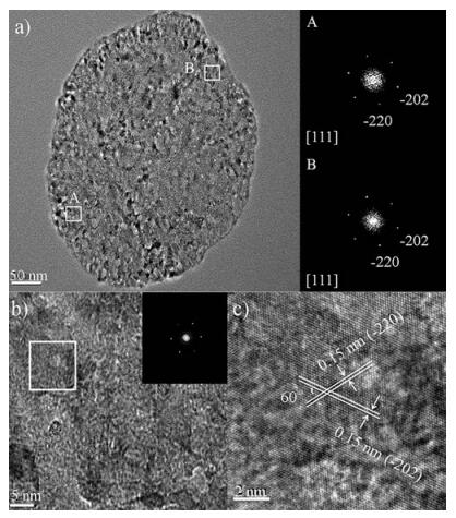
HRTEM was also utilized to prove that these MgO nanosheets are exposed with a large amount of (111) facets. The zone axis of the fast Fourier transformation (FFT) patterns is [111], indicating that the sheets with the exposed (111) planes lay on the specimen holder (Fig. 1a). The lattice fringes of 0.15 nm match the (-220) and (-202) lattice spacings in MgO (Figs. 1b and c), which suggests that the nanosheets grow along the direction perpendicular to [111]. The SAED patterns of several random-selected sheets also show that the most exposed facets of the nanosheets are (111) facets (Fig. S5 in Supporting information). The HRTEM images of a MgO nanosheet standing uprightly on the carbon film (Fig. S6 in Supporting information) exhibit lattice fringe with a distance of 0.24 nm, which is in agreement with the (111) lattice spacings in MgO.

|
Download:
|
| Fig. 1. (a) HRTEM image of a MgO nanosheet and FFT patterns of selected A and B parts. (b) HRTEM image of a MgO nanosheet (inserted is the corresponding FFT pattern) and (c) the lattice fringes of 0.15 nm corresponding to the (-220) and (-202) lattice planes enlarged from the selected white square in (b). | |
In the previous studies, specific ligands such as biological linkers [14] and interfacial entrapment reagents [21] or special treatments of the substrates [20] have been applied to fabricate controlled assembly of anisotropic metal nanomaterials. The specificity of those methods limited their applications in other anisotropic nanomaterials. A rational design based on surface polarity may bring a more general method to fabricate controlled assembly. Owing to the exposed polar facets of MgO, which may have different interactions with polar and non-polar molecules, a new strategy to manufacture controlled assembly of anisotropic metal oxide nanomaterials was developed in this work. Two different assemblies were obtained by dropping MgO nanosheets suspension onto the clean glass substrates and drying slowly at room temperature for one day along with further heating in the muffle furnace at 350 ℃ for 2 h to remove the residual solvents. The only difference is one used the polar solvent ethanol as dispersant (notated as sample PS) and another used the non-polar solvent cyclohexane as dispersant (notated as sample NPS).
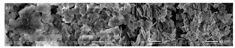
For the sample PS, SEM images (Figs. 2a and b) show that these nanosheets retain their original size and shape, and almost every sheet stacks in a face-down manner (on (111) plane) on the sample holder. For the sample NPS (Figs. 2c and d), these nanosheets also retain their size and shape, and most of them tend to stack with each other and stand along their edges on the sample holder. We describe this phenomenon as like disperses like, an extension of like dissolves like principle [22]. In the ethanol system, the sheets mainly with polar surfaces would be dispersed evenly in the polar solvent (Fig. S7a in Supporting information) because of the strong interaction between polar solvent molecules and polar MgO surfaces. Therefore, when the ethanol suspension was dropped onto the glass substrate, the nanosheets were face-to-face stacked on the substrate by the attracting force of ethanol among the nanosheets. After evaporation of ethanol, the assembly paralleled with the substrate remains (Figs. 2a and b). However, cyclohexane is a non-polar solvent so it would not be able to disperse the nanosheets well (Fig. S7b in Supporting information) due to the repulsion between non-polar solvent molecules and polar MgO surfaces. Thus, when the cyclohexane suspension was dropped onto the glass substrate, the surface tension of the interface between solvent and sheets is very high so that it can even drive the sheets to stand uprightly on the substrate during the evaporation of solvent (Figs. 2c and d). When methanol or acetonitrile was employed as the polar solvent and n-hexane or toluene was employed as the non-polar solvent, similar phenomena related to the polarity of solvents were observed (Fig. S8 in Supporting information). It is obvious that the polarity of dispersants plays a crucial role in the re-assembly of surface controlled nanocrystals [23].

|
Download:
|
| Fig. 2. SEM images of the MgO nanosheets prepared in ethanol (a, b) and cyclohexane (c, d). | |
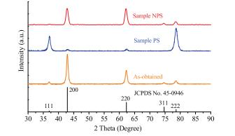
These two assemblies show distinct difference in XRD patterns (Fig. 3). In the XRD pattern of sample PS, two extremely strong peaks indexed as the (111) and (222) reflections and two weak peaks indexed as the (200) and (220) reflections can be observed. However, in the XRD pattern of sample NPS, the (111) and (222) reflections almost disappear while two strongpeaks indexed asthe (200) and (220) reflections can be observed. The XRD data indicate that preferred orientations exist in both samples.

|
Download:
|
| Fig. 3. XRD patterns of the samples prepared in different solvents. | |
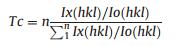
The degree of preferred orientation is illustrated by introducing Harris texture coefficient Tc [24], which is defined as in Eq. (1):
|
(1) |
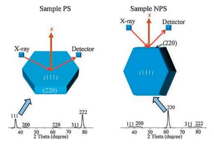
where Ix(hkl) is the relative intensity of the measured peak corresponding to the hkl diffraction, Io(hkl) is the relative intensity in the standard powder sample (JCPDS No. 45-0946), and n is the total number of calculated diffraction peaks. The value of Tc for the peak under investigation ranges from 1 for a randomly oriented sample, to n for a sample having a complete preferred orientation. We selected four peaks of (111), (200), (220) and (311) to estimate the degree of preferred orientation. According to the calculation, sample PS shows a preferred orientation of (111) with Tc of 3.8 (the maximum is 4.0) while sample NPS shows a preferred orientation of (220) with Tc of 2.2. Additionally, samples prepared in methanol and acetonitrile show a preferred orientation of (111) with Tc of 3.7 and 3.6, respectively, while samples prepared in n-hexane and toluene showa preferred orientation of (220) with Tc of 2.0 and 1.7, respectively, (Fig. S9 in Supporting information). In the XRD measurement (Scheme 1), besides that Bragg's law has to be satisfied, the planes to produce collectible scattered beams must also be perpendicular to the diffraction vector s (the vector that bisects the angle between the incident and diffracted beam).Otherwise, even the diffracted beams are produced, they will not be collected by the detector, and in other words the diffractions from those planes will be weakened in the XRD patterns. Considering the geometry of the MgO nanosheets, where the top and bottom faces of the sheets are (111) planes, and the side faces are (220) planes, the preferred orientation in XRD could be fullyexplained. It is because that the (111) planes are preferentially oriented parallel to the sample holder in sample PS and this alignment enhances the intensity of (111) diffraction. As in sample NPS, the (111) planes are preferentially oriented perpendicular to the sample holder and this alignment enhances the intensity of (220) diffraction. Scheme 1 illustrates the XRD patterns of ideally aligned MgO nanosheets with (111) planes perpendicular and parallel to the diffraction vector s. It is worth noting that the asobtained sample shows no obvious difference comparing with the standard powder sample (JCPDS No. 45-0946) (Fig. 3), indicating that the as-obtained sample contains randomly oriented nanosheets with no preferred orientation of the (111) planes.

|
Download:
|
| Scheme 1. Illustration of the occurrence of XRD patterns from ideally aligned MgO nanosheets with (111) planes perpendicular and parallel to the diffraction vector s. | |
It is also very interesting that two samples exhibit different optical properties. The UV-visible diffuse reflectance spectra in Fig. 4 reveal that the as-obtained sample shows two characteristic peaks at ~270nm and ~220nm, which could be assigned to threeand four-coordinated oxygen anions, respectively [25]. Moreover, the intensity of absorption at 270nm in sample PS is relatively high, while that in sample NPS is almost absent. The ~270nm peak corresponds to an excitation of electron transfer from the threecoordinated oxygen anions to the magnesium cations [26, 27]. Regarding the oxygen anions on (111) facets of MgO are threecoordinated (Fig. S10 in Supporting information), hence sample PS shows high intensity at ~270nm. However, for sample NPS with most sheets standing along their edges, (111) planes are perpendicular to the surface which leads to most three-coordinated oxygen anions in sample NPS are optically undetectable. Therefore, this work demonstrates that different structural and optical features of nanomaterials can be achieved through orientational assemblies, which provide a general way to fabricate nanomaterials to functional architectures.

|
Download:
|
| Fig. 4. UV-visible diffuse reflectance spectra of the as-obtained sample, sample PS and sample NPS. | |
In summary, we have successfully obtained MgO nanosheets with mainly exposed (111) facets by a simple chemical route. It has been demonstrated that, by tuning the polarity of dispersing solvents, the controlled assemblies of anisotropic nanomaterials can be achieved on a microscopic scale. Two anisotropic assemblies of MgO nanosheets have shown different properties in crystallography and optics compared with randomly arranged anisotropic MgO sample. The results may shed light on better understanding of the physicochemical properties related with the controlledanisotropic assemblyand pavethewayfor fabrication of new anisotropic architectures with potential optical, magnetic and catalytic applications.
AcknowledgmentThis work was supported by the National Natural Science Foundation of China (Nos. 21673046, 21473036, 21371035, 91645201).
Appendix A. Supplementary dataSupplementary data associatedwith this article can be found, in the online version, at https://doi.org/10.1016/j.cclet.2017.12.011.
| [1] |
B.M. Choudary, M.L. Kantam, K.V.S. Ranganath, K. Mahendar, B. Sreedhar, J. Am. Chem. Soc. 126 (2004) 3396-3397. DOI:10.1021/ja038954n |
| [2] |
B.Q. Xu, J.M. Wei, H.Y. Wang, K.Q. Sun, Q.M. Zhu, Catal. Today 68 (2001) 217-225. DOI:10.1016/S0920-5861(01)00303-0 |
| [3] |
G. Moussavi, M. Mahmoudi, J. Hazard. Mater. 168 (2009) 806-812. DOI:10.1016/j.jhazmat.2009.02.097 |
| [4] |
K. Refson, R.A. Wogelius, D.G. Fraser, et al., Phys. Rev. B 52 (1995) 10823-10826. DOI:10.1103/PhysRevB.52.10823 |
| [5] |
P. Geysermans, F. Finocchi, J. Goniakowski, R. Hacquart, J. Jupille, Phys. Chem. Chem. Phys. 11 (2009) 2228-2233. DOI:10.1039/b812376d |
| [6] |
K.K. Zhu, J.C. Hu, C. Kuebel, R. Richards, Angew. Chem. Int. Ed. 45 (2006) 7277-7281. DOI:10.1002/(ISSN)1521-3773 |
| [7] |
K.K. Zhu, W.M. Hua, W. Deng, R. Richards, Eur. J. Inorg. Chem. 17 (2012) 2869-2876. |
| [8] |
T. Xu, X. Zhou, Z.Y. Jiang, et al., Cryst. Growth Des. 9 (2009) 192-196. DOI:10.1021/cg8002096 |
| [9] |
M.S. Xue, Q.L. Guo, J. Chem. Phys. 127 (2007) 054705. DOI:10.1063/1.2756831 |
| [10] |
C. Yuan, X. Zhang, L. Su, B. Gao, L. Shen, J. Mater. Chem. 19 (2009) 5772-5777. DOI:10.1039/b902221j |
| [11] |
S. Mann, Nature Mater. 8 (2009) 781-792. DOI:10.1038/nmat2496 |
| [12] |
L. Ye, C.H. Yu, P.J. Jiang, et al., Chem. Commun. 46 (2010) 6699-6701. DOI:10.1039/c0cc01958e |
| [13] |
C.T. Black, C.B. Murray, R.L. Sandstrom, S. Sun, Science 290 (2000) 1131-1134. DOI:10.1126/science.290.5494.1131 |
| [14] |
C.J. Murphy, T.K. Sau, A.M. Gole, et al., J. Phys. Chem. B 109 (2005) 13857-13870. DOI:10.1021/jp0516846 |
| [15] |
J.P. Novak, D.L. Feldheim, J. Am. Chem. Soc. 122 (2000) 3979-3980. DOI:10.1021/ja000477a |
| [16] |
S. Malynych, G. Chumanov, J. Am. Chem. Soc. 125 (2003) 2896-2898. DOI:10.1021/ja029453p |
| [17] |
Y. Wang, X.Y. Chen, B. Yue, H.Y. He, Top. Catal. 55 (2012) 1022-1031. DOI:10.1007/s11244-012-9884-1 |
| [18] |
X.W. Xie, Y. Li, Z.Q. Liu, M. Haruta, W.J. Shen, Nature 458 (2009) 746-749. DOI:10.1038/nature07877 |
| [19] |
A. Mclaren, T. Valdes-Solis, G. Li, S.C. Tsang, J. Am. Chem. Soc. 131 (2009) 12540-12541. DOI:10.1021/ja9052703 |
| [20] |
C. Xue, Z. Li, C.A. Mirkin, Small 1 (2005) 513-516. DOI:10.1002/(ISSN)1613-6829 |
| [21] |
Y. Bae, N.H. Kim, M. Kim, K.Y. Lee, S.W. Han, J. Am. Chem. Soc. 130 (2008) 5432-5433. DOI:10.1021/ja800898v |
| [22] |
R.S. Ruoff, D.S. Tse, R. Malhotra, D.C. Lorents, J. Phys. Chem. 97 (1993) 3379-3383. DOI:10.1021/j100115a049 |
| [23] |
R. Si, Y.W. Zhang, H.P. Zhou, L.D. Sun, C.H. Yan, Chem. Mater. 19 (2007) 18-27. DOI:10.1021/cm0618392 |
| [24] |
M.I. Jones, I.R. McColl, D.M. Grant, Surf. Coat. Tech. 132 (2000) 143-151. DOI:10.1016/S0257-8972(00)00867-7 |
| [25] |
M.L. Bailly, G. Costentin, Lauron-Pernot H., J.M. Krafft, M. Che, J. Phys. Chem. B 109 (2005) 2404-2413. DOI:10.1021/jp048760+ |
| [26] |
M.C.C. Wobbe, A. Kerridge, M.A. Zwijnenburg, Phys. Chem. Chem. Phys. 16 (2014) 22052-22061. DOI:10.1039/C4CP03442B |
| [27] |
S. Stankic, M. Muller, O. Diwald, et al., Angew. Chem. Int. Ed. 44 (2005) 4917-4920. DOI:10.1002/(ISSN)1521-3773 |