 2018, Vol. 29


With the development of industry and agriculture, environmental pollution has become more and more serious, and heavy metal pollution has attracted widespread attention. Metallurgy, machinery manufacturing, electronic instruments and other industries produce a large number of heavy metal ionic pollutants [1, 2]. These contaminants had seriously affected human health and ecological environment due to their carcinogenicity, mutagenicity, and teratogenic properties in the biological system [3-5]. Hence, looking for cost-effective, green environmental heavy metal removal treatments had attracted considerable attention.
There are many methods to remove heavy metal ions from wastewater, such as electrolysis method, ion exchange method, adsorption method, membrane separation method, etc. [6-8]. In these methods, the adsorption method is widely used due to its high efficiency and economy [9, 10]. Various adsorbent materials have been used to remove heavy metals from wastewater, such as activated carbon, biopolymers, etc. [11-13]. However, most of the adsorbent materials are prone to secondary contamination, and it is difficult to separate and regenerate from the wastewater [14]. Currently, magnetic Fe3O4 materials have attracted wide attention due to their easy preparation, low toxicity, and effective magnetic separation [15-17]. However, the bare magnetic Fe3O4 is easily oxidized in the air and prone to agglomeration [18]. To protect the magnetic Fe3O4, many researchers have further modified the magnetic material [19, 20]. Zargoosh et al. used salicylhydrazide (TSH) and polyacrylic acid (PAA) to modified magnetic Fe3O4 [12]. Liu et al. reported that the EDTA modified magnetic Fe3O4 [5]. Another, some groups used magnetic Fe3O4 as a core, coated with silica, prepared many core-shell structure materials [21-23]. Some special groups have further branched on the silicon shell to increase the activity and the adsorption site of the material. Zhang et al. prepared five kinds of amino-functionalized magnetic Fe3O4/SiO2 submicron composites [24]. Zhao et al. prepared 3-aminopropyltriethoxysilane (APTES) functionalized magnetic core-shell structure material [25]. Amino functionalization has also been reported by other researchers [26, 27]. However, the adsorption effect is not very good and these studies have focused on Cr6+ and As3+, few on Cu2+ and Ni2+.
Dithiocarbamate (DTC), whose functional groups containing N and S coordination atoms easily complexing with metal ions, is an important metal ion traping agent [28, 29]. DTC is usually prepared by primary or secondary amine and carbon disulfide reacted in alkaline conditions, and the preparation process is simple and reaction conditions is mild [30, 31]. DTC heavy metal chelating agents have the following characteristics: -NH-CS2 groups have strong chelating ability, could effectively capture metal ions, then obtained a stable chelate precipitates [32, 33]. In addition, the formation of floc with wastewater is large, can quickly sedimentate. Recently, many researchers have synthesized different micromolecular DTC with various materials to obtained different efficient metal ionic chelating agents. Li reported a carbamidebased dithiocarbamate (CDTC) chelator for the removal of Cu2+ ion, the adsorption capability was 63.1 mg/g [33]. Liu et al. synthesized poly(dimethyldiallyl ammonium chloride-co-acrylamide)-grafttriethylenetetramine- dithiocarbamate chelator [34]. Yan et al. synthesized different carbon chain lengths EDTA-based dithiocarbamates [35]. Although some methods greatly improve its chelating performance, but it is difficult for chelator to recycle use.
In this paper, we prepared a new magnetic nanoparticle-based dithiocarbamate adsorbent (Fe3O4@SiO2-DTC) with core-shell structure, which combined the magnetic property of Fe3O4 with the strong adsorption performance of dithiocarbamate. The adsorption effect of the Fe3O4@SiO2-DTC was studied by adsorbing Ni2+ and Cu2+ ions. We investigated the effects of solution pH, adsorption time, and the initial concentration of heavy metal ions on the adsorption of Ni2+ and Cu2+. In addition, we also studied the adsorption kinetics and isotherms to analyze the adsorption mechanism, and obtain a plausible adsorption mechanism. Moreover, we also studied the recovery performance and selectivity of the adsorbent.
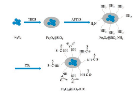
Fig. 1 shows the scheme for the synthesis of magnetic particles. Firstly, the Fe3O4 nanoparticle was prepared by coprecipitation method, then tetraethyl orthosilicate was hydrolyzed to orthosilicic acid under alkaline condition to prepare Fe3O4@SiO2. Secondly, the Fe3O4@SiO2 was further modified with APTES to obtained Fe3O4@SiO2-NH2. Finally, the Fe3O4@SiO2-NH2 reacted with carbon disulfide. Under alkaline conditions, the primary amine was deprotonated and then attacked to carbon positive ions, then obtained the target product Fe3O4@SiO2-DTC.

|
Download:
|
| Fig. 1. Scheme for the synthesis of Fe3O4@SiO2-DTC magnetic particles. | |
The XRD of the prepared samples were shown in Fig. S1 (Supporting information). For Fe3O4 (Fig. S1a), the characterisitic peaks at 2θ = 30.1°, 35.4°, 43.0°, 53.5°, 56.9°, 62.7°, and 73.7°, which correspond to (220), (311), (400), (422), (511), (440), and (533) planes of Fe3O4 (JCPDS No. 19-0629), respectively, and the sharp peaks indicated that the Fe3O4 has a certain degree of crystallinity [36]. In the XRD pattern of Fe3O4@SiO2 (Fig. S1b), a wide peak at 20°–30° was observed, indicating that silica was successfully coated on the surface of Fe3O4 in amorphous. As can be seen from Fig. S1, in the XRD patterns of Fe3O4@SiO2, Fe3O4@SiO2-NH2, and Fe3O4@SiO2-DTC, the characterisitic peaks of Fe3O4 were observed, indicating that the crystal structure of the Fe3O4 nanoparticles were unchanged.
The FTIR spectra of Fe3O4, Fe3O4@SiO2, Fe3O4@SiO2-NH2, and Fe3O4@SiO2-DTC magnetic particles were shown in Fig. S2 (Supporting information). For all four curves, an absorption peak at 563 cm-1 was observed, which correspond to the Fe-O bond stretching vibration of Fe3O4. For the curve of Fe3O4@SiO2 (Fig. S2b), absorption peaks at 1085, 968 and 464 cm-1 were observed, corresponding to Si-O-Si, Si-O-H and O-Si-O vibration of SiO2, respectively, which demonstrates silica was successfully coated on the surface of Fe3O4. The absorption peak at 3426 cm-1 can be ascribed to -OH stretching vibration of SiO2. The absorption peaks at 3393, 1644 and 769 cm-1 in the spectra of Fe3O4@SiO2-NH2 (Fig. S2c), attributed to the stretching and bending vibration of N-H. Furthermore, absorption peak of the stretching vibration of C-N at 1309 cm-1 can also be found. The absorption peaks at 1451 and 1384 cm-1 in the spectra of Fe3O4@SiO2-DTC (Fig. S2d), attributed to the stretching vibration of C-N. The absorption peak at 1049 and 1002 cm-1 were associated with the stretching vibrationof C = S and C-S, respectively. The above results indicate that the successful preparation of Fe3O4@SiO2-DTC. The EDS spectrum of Fe3O4@SiO2-DTC was shown in Fig. S3 (Supporting information). From Fig. S3, the peak of S element was observed, indicating that the successful preparation of Fe3O4@SiO2-DTC.
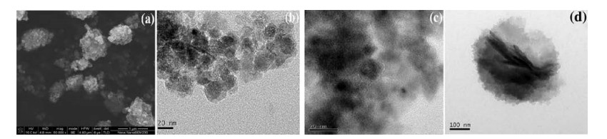
For the investigation of the morphology of the particles and estimating the particle size, SEM and TEM spectrums of particles were shown in Fig. 2. From the SEM image of Fig. 2a, the prepared Fe3O4 appeared an irregular oval shape with slightly aggregate. Reasons for aggregation may be related to too dense sampling. Fig. 2b was TEM image of Fe3O4@SiO2, an obvious core-shell structure can be clearly observed. The middle part of the black was Fe3O4 core, the edge of the gray part was the silica shell. The Fe3O4 particles tend to agglomerate into a larger particle during coated with silica. As the surface of the silica electrostatic repulsion, the particles have a certain degree of dispersion. The average diameter of the particle was approximately 26 nm and the thickness of the silica shell was about 6 nm. Fig. 2c was HR-TEM image of Fe3O4@SiO2. It can be observed that the Fe3O4 particles exhibits parallel lattice fringes, indicating their monocrystalline nature. No lattice pattern of the silica was observed, indicating the silica was amorphous, which was consistent with the XRD characterization results. After further modification, the particles size was gradually increased. From the TEM image of Fe3O4@SiO2-DTC (Fig. 2d), it can be observed that it was still an obvious core-shell structure and the average diameter of the particle was about 400 nm.

|
Download:
|
| Fig. 2. SEM image of Fe3O4 (a). TEM images of Fe3O4@SiO2 (b and c) and Fe3O4@SiO2-DTC (d). | |
The magnetic hysteresis loops of Fe3O4, Fe3O4@SiO2 and Fe3O4@SiO2-DTC were shown in Fig. S4a (Supporting information). Due to the remanence and coercivity were almost zero, the Fe3O4, Fe3O4@SiO2 and Fe3O4@SiO2-DTC exhibited typical superparamagnetic property, with the saturated magnetization values of 80.2, 65.5, and 52.7 emu/g, respectively. The high saturated magnetization and superparamagnetic behavior were the main reasons that the adsorbent can be recycled under the external magnetic force (Fig. S4a in Supporting information).
The pH of the heavy metal ionic solution affects not only the form of heavy metal ions in aqueous solution, but also changes the charge on the surface of the adsorbent in adsorption process [37, 38]. Therefore, to determined the optimum pH area, we investigated the effect of pH between 2.0 and 9.0 on adsorption reaction, and the results were shown in Fig. S5 (Supporting information). The optimum pH for the removal of Ni2+ and Cu2+ were 8.0 and 5.0, with the removal rate (R) value of 99.75% and 98.92%, respectively.
To study the effect of time on the adsorption reaction, the contact time was controlled between 5 min and 180 min, and the results were shown in Fig. 3. Obviously, with the increase of the contact time, the removal rate of Ni2+ and Cu2+ were increased rapidly, and reached equilibrium at 15 min and 90 min, respectively. When the time was 15 min, the removal rate of Ni2+ was over 99.5%, which was superior to other reported adsorbents [14].

|
Download:
|
| Fig. 3. Effect of adsorption time (t) on Ni2+ and Cu2+ adsorption at pH 8.0, 5.0, respectively. | |
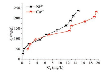
The kinetic fitting results were shown in Fig. S6 (Supporting information), and the parameters were summarized in Table S1 (Supporting information). The adsorption data were fitted with the pseudo-second-order model, indicating that the adsorption process was controlled by the chemical process [39]. We studied the effect of ionic concentration (25–250 mg/L) on adsorption reaction, and the results were shown in Fig. 4. With the increase of ionic concentration, the adsorption capacity of Ni2+ and Cu2+ were increased rapidly. The adsorption data were described by Langmuir and Frenundlich isotherm models. The isotherm data fitting results were shown in Fig. S7 (Supporting information), and the parameters were summarized in Table S2 (Supporting information). It can be observed that the R2 value of the Langmuir isotherm model were smaller than the Frenudlich model, indicating that the adsorption data were better fitted to the Frenudlich isotherm model. The results showed that the adsorption was multilayer, and the surface is heterojunction structure.

|
Download:
|
| Fig. 4. Effect of ionic concentration on Ni2+ and Cu2+ adsorption at pH 8.0, 5.0, respectively. | |
The adsorption capacities for Ni2+ and Cu2+ in aqueous solution of Fe3O4@SiO2-DTC in this paper are compared with those previously reported by other groups (Table S3 in Supporting information). When the initial concentration of heavy metal ions was 250 mg/L, the maximum adsorption capacity of Ni2+ and Cu2+ at room temperature was 235.23 mg/g and 230.49 mg/g, respectively.
To elucidate the adsorption process between Ni2+, Cu2+ and Fe3O4@SiO2-DTC, we proposed the plausible adsorption mechanism. According to the previous works, the adsorption mechansim of heavy metal ions by DTC was mainly dominated by chelation [34, 40]. There are many polar groups (-NH-CS2) on the surface of Fe3O4@SiO2-DTC, it is easily chelated with metal cations to produce a poorly soluble dithiocarbamate. This may be attributed to the reason that the atomic radius of the sulfur in the group is relatively large, negatively charged and easily polarized [35]. From Fig. 5, the corresponding metal cations (Ni2+ and Cu2+) adsorption process can be assumed as follows: firstly, due to the electrostatic interaction, the negatively charged groups on the surface of the adsorbent attract metal cations to the surface of the adsorbent; secondly, -NH-CS2 groups are polarized and chelated with metal cations; finally, produce a poorly soluble dithiocarbamate. Overall, the adsorption mechanism of metal cations (Ni2+ and Cu2+) by the Fe3O4@SiO2-DTC involved electrostatic interaction and chelation. The chelating could be intermolecular chelating or intramolecular chelating, but which chelating is predominant, it still to be further studied.

|
Download:
|
| Fig. 5. Scheme for the possibility adsorption mechanism of metal ions M2+ on Fe3O4@SiO2-DTC. M = Ni, Cu. | |
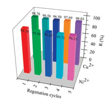
The results of regeneration performance and competitive adsorption of Ni2+, Cu2+, Zn2+ and Mg2+ were shown in Fig. 6 and Fig. S8 (Supporting information), respectively. It can be seen from Fig. 6 that the removal rate of Ni2+ and Cu2+ were still above 95% after the five regeneration cycles, indicating that the regeneration performance of the adsorbent is better. From Fig. S8, the adsorption sequence was Cu2+ > Ni2+ > Zn2+ > Mg2+ as they coexisted, indicating that the adsorbent could preferentially adsorb Ni2+ and Cu2+.

|
Download:
|
| Fig. 6. Regeneration of Fe3O4@SiO2-DTC for five cycles. | |
In this work, we synthesized a novel magnetic absorbent Fe3O4@SiO2-DTC with a core-shell structure for aqueous solution heavy metal ions Ni2+, Cu2+ removal. The large number of N and S coordination atoms groups adhered on the surface of the adsorbent are easily chelated with metal ions Ni2+ and Cu2+. The optimum pH for the removal of Ni2+ and Cu2+ were 8.0 and 5.0, respectively. The kinetic data indicated that the adsorption was chemical adsorption process. The isotherm data indicated that the adsorption was multilayer, and the surface was heterojunction structure. When the initial concentration of heavy metal ions was 250 mg/L, the maximum adsorption capacity of Ni2+ and Cu2+ at room temperature was 235.23 mg/g and 230.49 mg/g, respectively. The adsorbent loaded with heavy metal ions could be easily separated from aqueous solution by external magnetic field. After five adsorption-desorption cycles, the removal rate of Ni2+ and Cu2+ was still above 95%. In summary, the Fe3O4@SiO2-DTC is a novel, easy to prepare, environmentally friendly and effective adsorbent for the remove of Ni2+, Cu2+ from aqueous solution, which has great application prospects.
AcknowledgmentsThe authors greatly acknowledge the financial support provided by the National Natural Science Foundation of China (No. 21671026), the Science and Technology Key Project of Hunan Province (No. 2015SK20823), Scientific Research Key Fund of Hunan Provincial Education Department (No. 15A001), the Foundation of Hunan Provincial Key Laboratory of Materials Protection for Electric Power and Transportation (No. 2017CL06).
Appendix A. Supplementary dataSupplementary data associated with this article can be found, in the online version, at https://doi.org/10.1016/j.cclet.2017.11.029.
| [1] |
L. Xu, J.N. Wang, Y. Meng, A.M. Li, Chin. Chem. Lett. 23 (2012) 105-108. DOI:10.1016/j.cclet.2011.09.029 |
| [2] |
P. Panneerselvam, N. Morad, K.A. Tan, J. Hazard. Mater. 186 (2011) 160-168. DOI:10.1016/j.jhazmat.2010.10.102 |
| [3] |
A.Z.M. Badruddoza, Z.B.Z. Shawon, W.J.D. Tay, K. Hidajat, M.S. Uddin, Carbohyd. Polym. 91 (2013) 322-332. DOI:10.1016/j.carbpol.2012.08.030 |
| [4] |
F. Ge, M.M. Li, H. Ye, B.X. Zhao, J. Hazard. Mater. 211 (2012) 366-372. |
| [5] |
Y. Liu, M. Chen, H. Yongmei, J. Chem. Eng. 218 (2013) 46-54. DOI:10.1016/j.cej.2012.12.027 |
| [6] |
X. Zhang, Q. Huang, M. Liu, et al., Appl. Surf. Sci. 343 (2015) 19-27. DOI:10.1016/j.apsusc.2015.03.081 |
| [7] |
S.Y. Zhu, H.Y. Guo, F.F. Yang, Z.S. Wang, Chin. Chem. Lett. 26 (2015) 1091-1095. DOI:10.1016/j.cclet.2015.03.031 |
| [8] |
C.E. Barrera-Diaz, V. Lugo-Lugo, B. Bilyeu, J. Hazard. Mater. 223 (2012) 1-12. |
| [9] |
M. Bhaumik, A. Maity, V.V. Srinivasu, M.S. Onyango, J. Hazard. Mater. 190 (2011) 381-390. DOI:10.1016/j.jhazmat.2011.03.062 |
| [10] |
H. Zhang, F. Huang, D.L. Liu, P. Shi, Chin. Chem. Lett. 26 (2015) 1137-1143. DOI:10.1016/j.cclet.2015.05.026 |
| [11] |
J. Zhu, S.A. Baig, T. Sheng, et al., J. Hazard. Mater. 286 (2015) 220-228. DOI:10.1016/j.jhazmat.2015.01.004 |
| [12] |
K. Zargoosh, H. Abedini, A. Abdolmaleki, M.R. Molavian, Ind. Eng. Chem. Res. 52 (2013) 14944-14954. DOI:10.1021/ie401971w |
| [13] |
M. Hassan, E. Haque, K.R. Reddy, et al., Nanoscale 6 (2014) 11988-11994. DOI:10.1039/C4NR02365J |
| [14] |
H. Karami, J. Chem. Eng. 219 (2013) 209-216. DOI:10.1016/j.cej.2013.01.022 |
| [15] |
T. Wang, L. Zhang, H. Wang, et al., ACS Appl. Mater. Interfaces 5 (2013) 12449-12459. DOI:10.1021/am403533v |
| [16] |
T. Lü, S. Zhang, D. Qi, et al., Appl. Surf. Sci. 396 (2017) 1604-1612. DOI:10.1016/j.apsusc.2016.11.223 |
| [17] |
G. Yang, L. Tang, X. Lei, et al., Appl. Surf. Sci. 292 (2014) 710-716. DOI:10.1016/j.apsusc.2013.12.038 |
| [18] |
J.F. Liu, Z.S. Zhao, G.B. Jiang, Environ. Sci. Technol. 42 (2008) 6949-6954. DOI:10.1021/es800924c |
| [19] |
K.R. Reddy, K.P. Lee, A.G. Iyengar, J. Appl. Polym. Sci. 104 (2007) 4127-4134. DOI:10.1002/(ISSN)1097-4628 |
| [20] |
K.R. Reddy, K.P. Lee, A.I. Gopalan, Colloid. Surface A 320 (2008) 49-56. DOI:10.1016/j.colsurfa.2007.12.057 |
| [21] |
C. Hui, C. Shen, J. Tian, et al., Nanoscale 3 (2011) 701-705. DOI:10.1039/C0NR00497A |
| [22] |
H.L. Ding, Y.X. Zhang, S. Wang, et al., Chem. Mater. 24 (2012) 4572-4580. DOI:10.1021/cm302828d |
| [23] |
J. Zou, Y.G. Peng, Y.Y. Tang, RSC Adv. 4 (2014) 9693-9700. DOI:10.1039/c3ra47043a |
| [24] |
F. Zhang, Y. Shi, Z. Zhao, et al., J. Mater. Sci. 49 (2014) 3478-3483. DOI:10.1007/s10853-014-8060-3 |
| [25] |
W. Zhao, B. Cui, H. Peng, H. Qiu, Y. Wang, J. Phys. Chem. C 119 (2015) 4379-4386. DOI:10.1021/jp512447s |
| [26] |
K.R. Reddy, V.G. Gomes, M. Hassan, Mater. Res. Exp. 1 (2014) 015012. DOI:10.1088/2053-1591/1/1/015012 |
| [27] |
Y.P. Zhang, S.H. Lee, K.R. Reddy, A.I. Gopalan, K.P. Lee, J. Appl. Polym. Sci. 104 (2007) 2743-2750. DOI:10.1002/(ISSN)1097-4628 |
| [28] |
L. Bai, H. Hua, W. Fu, et al., J. Hazard. Mater. 195 (2011) 261-275. DOI:10.1016/j.jhazmat.2011.08.038 |
| [29] |
A. Farrukh, A. Akram, A. Ghaffar, et al., ACS Appl. Mater. Interfaces 5 (2013) 3784-3793. DOI:10.1021/am400427n |
| [30] |
D.J. Halls, Microchim. Acta 57 (1969) 62-77. DOI:10.1007/BF01216666 |
| [31] |
N. Azizi, E. Gholibeglo, RSC Adv. 2 (2012) 7413-7416. DOI:10.1039/c2ra20615c |
| [32] |
A. Hulanicki, Talanta 14 (1967) 1371-1392. DOI:10.1016/0039-9140(67)80159-0 |
| [33] |
Z. Li, J. Ind. Eng. Chem. 20 (2014) 586-590. DOI:10.1016/j.jiec.2013.05.018 |
| [34] |
L. Liu, J. Wu, X. Li, Y. Ling, Sep. Purif. Technol. 103 (2013) 92-100. DOI:10.1016/j.seppur.2012.10.028 |
| [35] |
P. Yan, M. Ye, S. Sun, et al., J. Clean. Prod. 122 (2016) 308-314. DOI:10.1016/j.jclepro.2016.02.037 |
| [36] |
K.R. Reddy, K.V. Karthik, S.B. Prasad, et al., Polyhedron 120 (2016) 169-174. DOI:10.1016/j.poly.2016.08.029 |
| [37] |
L. Zhou, H. Deng, J. Wan, J. Shi, T. Su, Appl. Surf. Sci. 283 (2013) 1024-1031. DOI:10.1016/j.apsusc.2013.07.063 |
| [38] |
A.M. Showkat, Y.P. Zhang, M.S. Kim, et al., Bull. Korean Chem. Soc. 28 (2007) 1985-1992. DOI:10.5012/bkcs.2007.28.11.1985 |
| [39] |
Y.S. Ho, G. McKay, Process Biochem. 34 (1999) 451-465. DOI:10.1016/S0032-9592(98)00112-5 |
| [40] |
B. Xiang, W. Fan, X. Yi, et al., Carbohyd. Polym. 136 (2016) 30-37. DOI:10.1016/j.carbpol.2015.08.065 |