 2018, Vol. 29


b State Key Laboratory of Advanced Technology for Materials Synthesis and Processing, Wuhan University of Technology, Wuhan 430070, China
The demand for efficient, economic, safe and eco-friendly energy storage systems (ESSs) is growing powerfully due to the rapid development of electronic equipment, electrical vehicles (EVs), clean energies, and so on [1]. EESs can be classified into two kinds based on the electrolytes: One is aqueous and the other is organic system. Organic electrolyte EESs generally have wide potential window but most of the concerns come from their toxicity, flammability and high cost [2]. As an alternative candidate, aqueous electrolyte EESs have been extensively investigated owing to superior safety, environmental friendliness and low cost [3-9]. Among them, aqueous hybrid supercapacitors (AHSCs) that are constructed with a high-capacity battery-type electrode and a high-rate capacitive electrode have attracted increasing attention in recent years [10-14]. Typically, such AHSCs not only can deliver high energy density as aqueous batteries, but also demonstrate high power density as conventional aqueous supercapacitors (SCs).
Designing high-performance AHSCs requires advanced electrode materials and mild electrolytes. Recent researches on AHSCs have led to the development of aqueous sodium ion hybrid supercapacitors (HSCs), which employ cheap aqueous neutral sodium-salts as the electrolytes [15]. Unfortunately, till now only limited battery-type anode materials such as NaTi2(PO4)3, poly(2-vinylanthraquinone) and polyimide can be utilized in aqueous sodium ion HSCs [16-18]. These anode materials store charges based on intercalation chemistry and thus give capacities lower than 150 mAh/g. To improve the energy density of aqueous sodium ion HSCs, it is particularly important to explore high-capacity anode materials. In 2016, our group discovered that bismuth oxide (Bi2O3) was able to electrochemically store charges in aqueous neutral sodium salts based on a unique "quasi-conversion reaction" mechanism [19]. This finding provides an opportunity for us to further develop Bi2O3-based aqueous sodium ion HSCs. Although Bi2O3 was previously investigated in organic electrolyte lithium ion and sodium ion batteries as well as aqueous alkaline electrolyte HSCs [20-29], its application in aqueous sodium ion HSCs has never been reported.
In this work, we synthesize a Bi2O3 nanoflake film directly on carbon cloth (CC) current collector as the battery-type anode for aqueous sodium ion HSCs. The nanoflake architecture has several advantages. First, it helps facilitate the electron transport and ion diffusion, thus improving the reaction kinetics and giving high capacity and high rate. Second, it does not contain binders and additives, avoiding the "dead volume" within the electrode. In particular, continuous carbon is integrated into the interspacing of nanoflakes, which not only enhances the electron transfer but also buffers volume expansion of Bi2O3, helping maintaining the cycling stability of electrode film [30, 31]. As a result, the Bi2O3@C electrode exhibits a high capacity of 207 mAh/g at 2 A/g (6C) with excellent rate performance and cycling stability up to 1000 cycles. An aqueous sodium ion HSC device is further assembled by using our Bi2O3@C as the anode and commercial activated carbon (AC) as the cathode, which achieves an energy density of 18.94 Wh/kg.
Pristine Bi2O3 nanoflake film was firstly grown on the CC current collector by a simple hydrothermal method (for comparative study). The reaction solution was prepared by dissolving 0.6 g of Bi(NO3)3·5H2O into 18 mL of ethylene and 36 mL acetone; the resulting suspension was kept stirring until clear before it was transferred into a Teflon-lined stainless steel autoclave (100 mL). With a piece of 2 × 2.5 cm2 CC immersed in the reaction solution, the autoclave was sealed and maintained at 160 ℃ for 5 h. After the reaction, the CC substrate with Bi2O3 nanoflakes grown on was washed in deionized water and finally dried at 60 ℃.
The Bi2O3@C film was further obtained by dropping 1 mol/L aqueous glucose solution on the Bi2O3 film and subsequent annealing at 650 ℃ for 2 h under Ar/5% H2 atmosphere (with a 5 ℃/min heating rate).
The commercial AC powder was purchased without further treatment. The electrode slurry was firstly prepared by mixing the AC powder with carbon black and PTFE with a weight ratio of 6:2:2 in isopropyl alcohol. The slurry was stirred, then casted on stainless steel, and finally pressed under 10 MPa for 5 min using a table machine and dried at 120 ℃ for 12 h under vacuum condition.
The morphology of the electrode materials were characterized using scanning electron microscopy (SEM; Hitachi S-4800, Japan). The elemental mapping was performed by using X-ray energy dispersive spectroscopy (EDS) equipped on SEM. The crystalline structure was characterized by X-ray diffraction (XRD; Bruker D-8 Advance, Cu Kα). The mass of the active materials was recorded by an ME 204 E Balance (METTLER TOLEDO, Maximum = 220 g; d = 0.0001 g).
The electrochemical measurement of each electrode was performed on a CS310 electrochemical workstation at room temperature by a standard three-electrode configuration, with the as-prepared film electrode as the working electrode, a platinum plate as the counter electrode, and saturated calomel electrode (SCE) as the reference electrode in a mixed electrolyte of 1 mol/L Na2SO4 and 2 mol/L NaCl (v:v = 1:1). For two electrode testing, AC powder was used as the working electrode and Bi2O3@C as the counter electrode. Electrochemical impedance spectroscopy (EIS) was measured by applying an open circuit potential (OCV) with 10 mV amplitude in the frequency range between 0.01 Hz–100 kHz.
The specific capacities of Bi2O3-based electrodes were measured by galvanostatic charge/discharge method based on the equation: Qs = I × Δt, where I is the constant current density (A/g) and Δt is the total discharging time. The capacitances of the device were calculated by using Cs = I × Δt/ΔV, where ΔV is the voltage of the device excluding the IR drop. The gravimetric energy and power densities (E and P) of the full cell were calculated using 
The morphology of the product was firstly investigated by SEM. Fig. 1 shows the SEM images of the pristine Bi2O3 and Bi2O3@C films grown on CC. As displayed in Fig. 1a, Bi2O3 has covered the entire surface of the conductive CC. Enlarged SEM image in Fig. 1b further indicates that the Bi2O3 film is made up of numerous vertically aligned nanoflakes with average lateral size of 200 nm and thickness of < 10 nm; the film thickness is ~400 nm, as shown in the inset of Fig. 1b. After the high-temperature carbonization process, the glucose is transformed into carbon, which facilely fills in the gaps of the nanoflakes (Figs. 1c and d), forming a continuous carbon film. EDS mapping in Figs. 1e–g also confirm the uniform distribution of Bi, O and C elements. It is believed that the obtained Bi2O3@C film electrode has unique merits for electrochemical energy storage. In such a structure, while the kinetics advantages of binder- and additive-free electrodes can be maintained, the carbon matrix can efficiently restrict the huge volume expansion and structural dissolution of the electrode arising from the multiphase changes of bismuth oxide. All these features would enable good comprehensive electrochemical performance, as will be discussed later.

|
Download:
|
| Fig. 1. (a) and (b) SEM images of the pristine Bi2O3 nanoflake film. The inset in Fig. 1b is the cross-sectional image. (c) and (d) SEM images of the Bi2O3@C film. The marked red rectangle indicates the EDS mapping area. (e–g) EDS mapping results of the Bi2O3@C film. | |
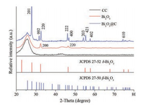
The pristine Bi2O3 film and the Bi2O3@C hybrid film were examined by XRD and the results are illustrated in Fig. 2. For pristine Bi2O3, the sharp peaks at 2θ = 32.3° and 46.4° can be well indexed to the (200) and (220) planes of δ-Bi2O3 (JCPDS card No. 27–52), respectively. For Bi2O3@C, diffraction peaks assigned to (201), (002), (220), (222), (400), (203), (421), (402) and (601) planes of β-Bi2O3 (JCPDS card No. 27–50) can be obviously detected, indicative of the phase transition of Bi2O3 after hightemperature treatment. The peak at ~25.6° is from the CC current collector. No other peaks can be found, indicating the high purity of the as-prepared films.

|
Download:
|
| Fig. 2. XRD patterns of CC substrate, pristine Bi2O3 film, and Bi2O3@C film. | |
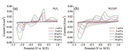
The electrochemical behavior of both the Bi2O3-based anodes and the AC cathode was firstly investigated in a three-electrode system in a neutral mixed electrolyte of 1 mol/L Na2SO4 and 2 mol/L NaCl (v:v = 1:1). Fig. 3 shows typical cyclic voltammetry (CV) curves of pristine Bi2O3 and Bi2O3@C hybrid film electrodes at scan rates of 1–50 mV/s, respectively. Both the CV curves exhibit obvious battery-like features with several redox peaks, which could be assigned to the reversible processes of Bi2O3 ↔ Bi2+ ↔ Bi0. The total chemical reaction can be expressed as follows [19]: Bi2O3 + 3 H2O + 6 e- ↔ 2 Bi0 + 6 OH-. As the scan rate increases, the anodic peak shifts to a more positive potential while the cathodic peak shifts to a more negative potential, owing to the polarization effect of battery electrodes. In addition, it can be seen that the CV profile in Fig. 3b includes some capacitive effect that should be ascribed to the hybridization of continuous carbon matrix.

|
Download:
|
| Fig. 3. CV curves of (a) pristine Bi2O3 and (b) Bi2O3@C film electrodes at various scan rates. | |
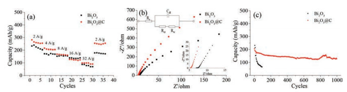
To evaluate the effect of the carbon hybridization, the rate capability and the cycleability of the Bi2O3 and Bi2O3@C film electrodes are comparatively studied and the results are shown in Fig. 4a and b. As displayed in Fig. 4a, the Bi2O3@C electrode always demonstrates higher capacity than the pristine Bi2O3. In particular, after continuously increasing the current density to 32 A/g and then decreasing back to 2 A/g (6C), ~95.0% of the initial capacity can be recovered. By contrast, the rate capacity recovery for the pristine Bi2O3 electrode is only ~78% under such condition. Our Bi2O3@C film electrode also demonstrates better rate performance than previous Bi2O3-based electrodes in aqueous electrolytes such as Bi2O3/carbon nanofiber (26.1 mAh/g at 1.67 A/g, 14.1 mAh/g at 16.7 A/g) [27] and Bi2O3 (70.6 mAh/g at 2 A/g, 29.8 mAh/g at 20 A/g) [32]. EIS results of the two electrodes are further shown in Fig. 4b to better elucidate the rate performance difference. Both the two electrodes exhibit a straight line in the low-frequency region and a semicircular loop in the high-frequency region. The diameter of the semicircular loop represents the charge transfer resistance (Rct) at the electrode-electrolyte interface, while the intercept on the xaxis at the high frequency represents the bulk electrolyte solution resistance and intrinsic resistance of the active material (Rs). An equivalent circuit made up of Rs, Rct, the double-layer capacitance (Cdl) and the resistance related to ion diffusion (Rw) was used to fit the EIS data. As can be seen, the Bi2O3@C electrode exhibits smaller Rs of 5.2V, as compared to that of the pristine Bi2O3 electrode (6.91V); the Rct is also slightly smaller; the gradient of the sloping line of the Bi2O3@C electrode is larger than Bi2O3 electrode, implying faster ion diffusion in the Bi2O3@C electrode. These results clearly indicate higher electrical conductivity and better electroactivity of the Bi2O3@C electrode, which should be beneficial from the presence of glucose-derived carbon matrix as well as the close interfacial contact between Bi2O3 and such carbon, and should account for the observed better rate capability. During the long-term cycling testing at 2 A/g (Fig. 4c), ~63% of the initial capacity can be maintained after 1000 cycles for the Bi2O3@C electrode, while that of the pristine electrode fades rapidly even during the first 100 cycles. This phenomenon highlights the great importance of the carbon matrix for stabilizing the electrode integrity. The cycling performance of Bi2O3@C electrode is superior to those of reported Bi2O3 electrodes such as Bi2O3 nanoparticles (60%, 1000 cycles, in 6 mol/L KOH) [29] and AC-Bi2O3 (59%, 1000 cycles, in 6 mol/L KOH) [26].

|
Download:
|
| Fig. 4. (a) Rate capability comparison of the pristine Bi2O3 and Bi2O3@C electrodes at different current densities. (b) Nyquist plots with the equivalent circuit. Inset is the enlarged spectrum. (c) Cycling performance at 2 A/g. | |
To further demonstrate the application potential of the Bi2O3@C electrode in aqueous sodium ion HSCs, a full cell was assembled by paring with commercial AC cathode and was test in mixed sodium ion electrolyte. The CV curves of the Bi2O3@C anode and AC cathode at a scan rate of 5 mV/s are both shown in Fig. 5a, from which the almost rectangular CV profile representing a capacitive behavior can be observed. By fully utilizing the potential window of anode and cathode, a stable operating voltage of 1.9 V can be achieved for the full cell. Fig. 5b illustrates the CV curves of the AC// Bi2O3@C HSC at various scan rates from 1 mV/s to 50 mV/s. The device exhibits good CV symmetry with broad redox peaks. Corresponding to the CV, the discharge curves at different current densities in Fig. 5c are characterized with some sloping plateaus. When the current density increases from 2 A/g to 16 A/g (6C–48C), the specific capacitance of the device corresponds to 47 F/g–14.8 F/ g, exhibiting a good capacitance retention of 31%. At a very high current density of 16 A/g (48C), the device still retain good electrochemical behavior, indicative of high rate performance. The Nyquist plot in Fig. 5d confirms that the fast electrode kinetics might be due to the low Rs value (10.6V) and Rct value (~5.0V) of the device. Besides, our device also exhibits excellent cycling stability at 2 A/g with capacity retention of 72.3% after 650 cycles (Fig. 5f). The maximum energy density and power density are estimated to be 18.94 Wh/kg and 1267 W/kg, respectively. The energy density is higher than those of many reported supercapacitors such as Bi2O3//AC (10.2 Wh/kg) [22], Bi2O3//MnO2 (11.3 Wh/kg) [27] and Bi2O3-Ni-F//graphite (11 Wh/kg) [28].

|
Download:
|
| Fig. 5. Electrochemical performance of the AC//Bi2O3@C HSC: (a) CV curves of anode and cathode at 5 mV/s. (b) CV curves of the device at different scan rates. (c) Discharge curves at different current densities. Inset is the plot of rate capability. (d) Nyquist plot. (e) Cycling performance at 2 A/g | |
In summary, we have reported the facile synthesis of a freestanding Bi2O3@C film anode for aqueous sodium ion HSCs. With carbon integration, the electrode demonstrates improved cycling stability (from only one hundred cycles to one thousand cycles), good rate performance and a high specific capacity of 207 mAh/g. The outstanding electrochemical performance can be attributed to the fast charge transfer kinetics (benefited from the binder-and additive-free electrode architecture) and the carbon matrix modification. Furthermore, the assembled AC//Bi2O3@C aqueous HSC delivers high energy density (18.94 Wh/kg), high power density (1267 W/kg), and excellent cycling stability (650 cycles, 72.3% retention). Our work not only developed promising highcapacity anode for aqueous sodium ion HSCs, but also may shed light on designing other aqueous electrochemical energy storage devices.
AcknowledgmentsThis work was supported by grants from the National Natural Science Foundation of China (Nos. 51672205 and 21673169), the National Key R & D Program of China (No. 2016YFA0202602), the Research Start-Up Fund from Wuhan University of Technology, and the Fundamental Research Funds for the Central Universities (Nos. 2016IVA083, 2017IB005).
| [1] |
R. Li, Z. Lin, X. Ba, et al., Nanoscale Horiz. 1 (2016) 150-155. DOI:10.1039/C5NH00100E |
| [2] |
L. Suo, O. Borodin, T. Gao, et al., Science 350 (2015) 938-943. DOI:10.1126/science.aab1595 |
| [3] |
M.W. And, R.J. Brodd, Chem. Rev. 105 (2005) 1021-1021. DOI:10.1021/cr040110e |
| [4] |
N.S. Choi, Z. Chen, S.A. Freunberger, et al., Angew. Chem. Int. Ed. 51 (2012) 9994-10024. DOI:10.1002/anie.201201429 |
| [5] |
Y. Wang, J. Yi, Y. Xia, Adv. Energy Mater. 2 (2012) 830-840. DOI:10.1002/aenm.201200065 |
| [6] |
W. Zuo, P. Xu, Y. Li, J. Liu, Nanomaterials 5 (2015) 1756-1765. DOI:10.3390/nano5041756 |
| [7] |
H. Sun, X. Fu, S. Xie, Y. Jiang, H. Peng, Adv. Mater. 28 (2016) 2070-2076. DOI:10.1002/adma.201505742 |
| [8] |
Z. Pei, M. Zhu, Y. Huang, et al., Nano Energy 20 (2016) 254-263. DOI:10.1016/j.nanoen.2015.12.025 |
| [9] |
Y. You, Z. Sang, J. Liu, Mater. Technol. 31 (2016) 501-509. DOI:10.1080/10667857.2016.1189709 |
| [10] |
L.Y. Liu, X. Zhang, H.X. Li, et al., Chin. Chem. Lett. 28 (2017) 206-212. DOI:10.1016/j.cclet.2016.07.027 |
| [11] |
B.S. Shen, H. Wang, L.J. Wu, et al., Chin. Chem. Lett. 27 (2016) 1586-1591. DOI:10.1016/j.cclet.2016.04.012 |
| [12] |
C. Xuan, Z. Peng, J. Wang, et al., Chin. Chem. Lett. 28 (2017) 2227-2230. DOI:10.1016/j.cclet.2017.09.009 |
| [13] |
J. Liu, C. Guan, C. Zhou, et al., Adv. Mater. 28 (2016) 8732-8739. DOI:10.1002/adma.201603038 |
| [14] |
L.R. Wang, F. Ran, Y.T. Tan, et al., Chin. Chem. Lett. 22 (2011) 964-968. DOI:10.1016/j.cclet.2011.01.019 |
| [15] |
W. Zuo, R. Li, C. Zhou, et al., Adv. Sci. 4 (2017) 1600539. DOI:10.1002/advs.v4.7 |
| [16] |
Z. Li, D. Young, K. Xiang, W.C. Carter, Y.M. Chiang, Adv. Energy Mater. 3 (2013) 290-294. DOI:10.1002/aenm.v3.3 |
| [17] |
H. Qin, Z.P. Song, H. Zhan, Y.H. Zhou, J. Power Sources 249 (2014) 367-372. DOI:10.1016/j.jpowsour.2013.10.091 |
| [18] |
W. Choi, D. Harada, K. Oyaizu, H. Nishide, J. Am. Chem. Soc. 133 (2011) 19839-19843. DOI:10.1021/ja206961t |
| [19] |
W. Zuo, W. Zhu, D. Zhao, et al., Energy Environ. Sci. 9 (2016) 2881-2891. DOI:10.1039/C6EE01871H |
| [20] |
Y. Li, M.A. Trujillo, E. Fu, et al., J. Mater. Chem. A 1 (2013) 12123-12127. DOI:10.1039/c3ta12655b |
| [21] |
M.K. Kim, S.H. Yu, A. Jin, et al., Chem. Commun. 52 (2016) 11775-11778. DOI:10.1039/C6CC06712C |
| [22] |
S.T. Senthilkumar, R.K. Selvan, M. Ulaganathan, J.S. Melo, Electrochim. Acta 115 (2014) 518-524. DOI:10.1016/j.electacta.2013.10.199 |
| [23] |
J. Li, Q. Wu, G. Zan, et al., Eur. J. Inorg. Chem. 35 (2015) 5751-5756. |
| [24] |
K. Gopalsamy, Z. Xu, B. Zheng, et al., Nanoscale 6 (2014) 8595-8600. DOI:10.1039/C4NR02615B |
| [25] |
C. Nithya, ChemPlusChem 80 (2015) 1000-1006. DOI:10.1002/cplu.201402394 |
| [26] |
S.X. Wang, C.C. Jin, W.J. Qian, J. Alloys Compd. 615 (2014) 12-17. DOI:10.1016/j.jallcom.2014.06.149 |
| [27] |
H. Xu, X. Hu, H. Yang, et al., Adv. Energy Mater. 5 (2015) 1401882-1401888. DOI:10.1002/aenm.201401882 |
| [28] |
N.M. Shinde, Q.X. Xia, J.M. Yun, et al., Dalton Trans. 46 (2017) 6601-6611. DOI:10.1039/C7DT00953D |
| [29] |
X. Huang, W. Zhang, Y. Tan, et al., Ceram. Int. 42 (2016) 2099-2105. DOI:10.1016/j.ceramint.2015.09.157 |
| [30] |
R. Li, Y. Wang, C. Zhou, et al., Adv. Funct. Mater. 25 (2015) 5384-5394. DOI:10.1002/adfm.201502265 |
| [31] |
S.L. Yang, L.P. Huang, H.B. Zhang, et al., Chin. Chem. Lett. 26 (2015) 1293-1297. DOI:10.1016/j.cclet.2015.05.051 |
| [32] |
H. Zheng, H. Li, M. Yu, et al., J. Mater. Chem. A 5 (2017) 25539-25544. DOI:10.1039/C7TA08451J |