 2018, Vol. 29


b Key Laboratory of Advanced Braided Composites, Ministry of Education, School of Textiles, Tianjin Polytechnic University, Tianjin 300387, China
In the recent decades, research focus is directed toward the development of high performance energy storage devices. Among various electrochemical energy storage devices, lithium ion battery (LIB) with high energy density and supercapacitor (SC) with high power density and superior cycle performance are the well-known promising technologies for the utilization of energy [1-4]. However, LIB and SC cannot independently meet the requirement for the high-performance energy storage devices which can exhibit high energy and power density as well as excellent cycling performance at the same time. Lithium ion capacitor (LIC), also called hybrid supercapacitor or asymmetric supercapacitor, is composed with a supercapacitor-type electrode and a lithium ion battery-type electrode in an organic electrolyte containing lithium salt [5-7]. Due to the electrode materials combination, LIC possesses higher energy density than supercapacitor and higher power density and longer cycle life than lithium ion battery.
The activated carbon cathode materials together with lithium intercalation anode materials are the most common combination in the various electrode materials. Graphite material (natural flake graphite and artificial graphite) and hard carbon (HC) material are other promising anode materials due to their high specific capacity, natural abundance and relatively low cost. Khomenko et al. introduced a LIC assembled with activated carbon cathode and graphite anode, the gravimetric and volumetric energy densities as high as 103.8 Wh/kg and 111.8 Wh/L could be obtained, and the discharge capacitance of such LIC could still keep more than 85% of the initial value after 10000 cycles [8]. Hard carbon (HC) is a particularly desirable anode material for high power device due to its characteristics of higher lithium ion solid diffusion kinetics and larger space gap between the carbon layers than graphite. Kim et al. compared the electrochemical performance of hard carbon and graphite anode material, and found that LIC with HC anode showed higher power density and cycle stability at large charge-discharge rate in comparison with the LIC using graphite as anode [9].
As we know, due to the high specific surface area, porous structure for rapid ion diffusion, good processability and low cost [10], commercially available activated carbon (AC) was commonly used as a typical cathode material for LIC. Recently, some novel carbon materials have been prepared and used as LIC cathode material. Jain et al. fabricated a high energy LIC using teak wood sawdust derived mesoporous activated carbon with electrochemically pre-lithiated graphite, it can delivered the energy density of 111 Wh/kg and maintained stable cycling behavior after 2000 cycles at the current density of 0.5 A/g [11]. During the charge-discharge process of a LIC, the specific capacity and energy density of LIC depend on the charge adsorptiondesorption behavior of the cathode material. Therefore, the structure characteristic and electrochemical performance of cathode carbon materials play an important role in achieving high energy density for LIC devices.
In this work, we synthesized the mesoporous carbon material with high surface area and large pore volume by a simple situ MgO template method [12, 13]. The structural characterization of MC was shown in Fig. 1. The synthesis details can be found in Supporting information. Besides, we introduced pre-lithiated graphite material and hard carbon material as the anode, and assembled LIC with mesoporous carbon cathode. The electrode preparation and LIC fabrication details can be found in Supporting information.

|
Download:
|
| Fig. 1. (a) X-ray diffraction pattern of MC. (b) BJH pore size distributions of MC. Inset: Nitrogen adsorption/desorption isotherms of MC at 77 K. (c–d) HRTEM image of MC. | |
Fig. 1 summarizes the structural characterization of MC. It is observed that two broad diffraction peaks positioned near 2θ values of 24.04° and 43.40° reflect the existence of graphite crystallite in MC carbonaceous material. Besides, the broad diffraction peak appeared at about 24.04° indicates the amorphous characteristic of MC. According to the IUPAC classification, the sample shows type pe Ⅳ adsor adsorption isotherms. It can be qualitative judged that the carbonaceous material is mesoporous carbon material based on the sharp of the nitrogen adsorption isotherms and hysteresis loop phenomenon [14]. The BET specific surface area of MC reaches up to 1432 m2/g and the pore volume is as high as 2.894 cm3/g. The pore size distribution shows that MC possesses pore size centered at 6.5 nm (Table S1 in Supporting information). The high surface area, large pore volume and appropriate mesopore size distribution of MC are beneficial to the charge accumulation and the transmission of electrolyte ions. HR-TEM images of MC (Figs. 1c and d) show that MC has a disordered mesoporous structure, and the mesoporous channels are interconnected. The thin walls of pores connect the pores with each other, thus constructing the entire conducive network. The chargedischarge curves of MC and AC in the range of 2.0–4.0 V show excellent linear with time (Fig. S1 in Supporting information). The specific capacity obtained from the discharge curve of the MC cathode was about 67.65 mAh/g between 2.0 V and 4.0 V and the specific capacity of commercial AC was about 49.95 mAh/g. Compared with AC electrode, MC electrode exhibits higher capacitance with 92.7% retention after 2000 cycles. The appropriate mesoprous pore size distribution and the high specific surface area of MC are conducive to the charge accumulation and transmission, leading to the increase of specific capacity.
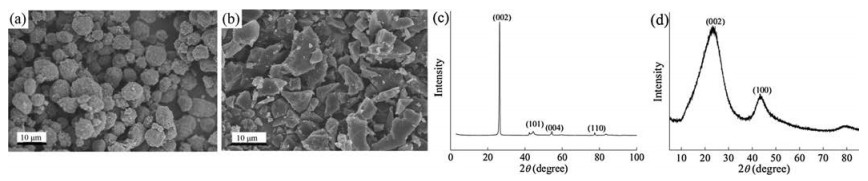
The structural characterization of MCMB and HC materials are shown in Fig. 2. The FE-SEM image of MCMB shows that the particles are evenly distributed with a size of approximate 10 μm. A strong (002) diffraction peak of MCMB is observed at 26.38°, which is the characteristic peak of graphite. The spacing of the graphite layer (d002) is 0.337 nm. The HC particles exhibit irregular shape with sharp edge, and its average particle size is about 10 μm, interspersed with some 3–5 μm particles. The XRD pattern of HC shows two broad diffraction peaks, the peaks at 23.74°, 43.54° are correlated to (002) and (100) diffraction peaks. The interlayer spacing (d002) is approximate 0.375 nm. This spacing is larger than the interlayer spacing of MCMB, which is conductive to the intercalation and de-intercalation of lithium ion. The first and second charge-discharge curves of MCMB show that the chargedischarge curve is relatively flat at low potentials (< 0.25 V) (Fig. S2 in Supporting information). The first intercalation capacity and the irreversible capacity loss of MCMB are about 370 mAh/g and 30 mAh/g, respectively. There are two peaks at the potential of about 1.2 V and 0.7 V during the first cathodic scan, and the peaks disappear in the subsequent cycling in the cyclic voltammograms of MCMB/Li cell. It is believed that the two peaks are associated with the formation of solid electrolyte interface (SEI) film on the MCMB surface due to the decomposition of electrolyte, which accounts for the vast majority of the irreversible loss (ICL) [15]. The HC exhibits a reversible discharge capacity of 487 mAh/g and a charge capacity of 390 mAh/g in the first charge-discharge cycle. A distinct lithium ion intercalation plateau near about 0 V is observed, which reflects the lithium ion intercalation on the micropores [16]. It can be seen that two cathodic peaks emerge at the potential of about 1.1 V and 0.7 V in the cyclic voltammograms of HC/Li cell, which also corresponds to the formation of SEI film. The peaks below 0.2 V are related to the intercalation of lithium ion in the graphite crystallite layers and micropores.

|
Download:
|
| Fig. 2. FESEM image of (a) MCMB and (b) HC, XRD pattern of (c) MCMB and (d) HC. | |
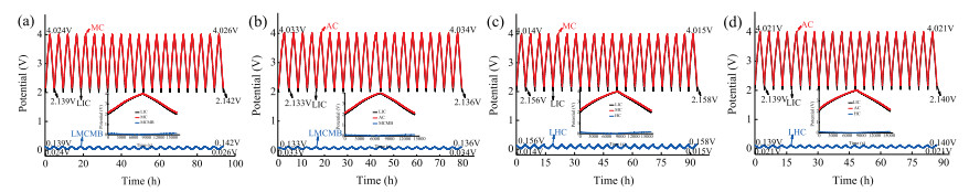
For investigating the electrochemical behavior of the cathode, anode and LIC device during the galvanostatic charge-discharge process, the first 20 cycles charge-discharge profiles of the threeelectrode LIC at a current density of 25 mA/g are exhibited in Fig. 3. During the first galvanostatic charge-discharge of LIC between 2.0 V and 4.0 V, the profile of the MC cathode, AC cathode and LIC device exhibit almost linear relationship with time, indicating excellent capacitance behavior. Compared with the AC cathode used in LIC–AC/MCMB and LIC–AC/HC, MC cathode shows higher specific capacitance (Table S2 in Supporting information). The cathode and anode during the charge-discharge process maintain the capacity balancing, so the increase of cathode capacitance will improve the lithium ion intercalation and de-intercalation degree of anode, leading to the broaden of anode discharge potential range. The discharge potential range of MCMB anode swings from 0.102 V to 0.116 V, and the discharge potential range of HC anode also increase from 0.118 V to 0.143 V. Besides, it can be noted that all the charge-discharge potential range of MC cathode and MCMB or HC anode remain almost constant throughout the cycling process, indicating that the stable work potential ranges of cathode and anode are conducive to the LIC cycling stability.

|
Download:
|
| Fig. 3. The first 20 cycles charge-discharge profiles of three-electrode LIC at 25 mA/g. (a) LIC–MC/MCMB, (b) LIC–AC/MCMB, (c) LIC–MC/HC, (d) LIC–AC/HC. Insert: The first charge-discharge profile. | |
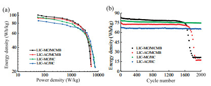
The electrochemical performance of LIC between 2.0 V and 4.0 V is shown in Fig. 4. The maximum energy density as shown in Ragone plots are about 101.1 Wh/kg and 95.4 Wh/kg, the maximum power densityare 5.2 kW/kgand 7.4 kW/kgfor LIC–MC/MCMB andLIC–MC/HC. In contrast, the maximum energy density is about 92.3 Wh/kg and 85.7 Wh/kg, the maximum power density is 5.5 kW/kg and 7.6 kW/kg for LIC–AC/MCMB and LIC–AC/HC. It can be seen that the energy density of LIC using MC as cathode is higher than the LIC using AC as cathode, which proved that the cathode capacitance improvement leads to the increase of LIC's energy density. The increase of MC cathode capacitance improves the lithium ion intercalation and de-intercalation degree of anode, resulting in little sacrifice of power density. In addition, LIC using the HC as anode exhibits higher power density than the LIC using MCMB as anode, indicating good rate performance. The electrochemical impedance spectra measurement was operated under the same open circuit potential over a frequency range from 10 mHz to 100 kHz with a signal amplitude of 5 mV. All the EIS profile are fitted by the electric equivalent circuit model [17]. As can be seen, all the EIS profiles are made up of three parts, two depressed semicircles in the high-tomedium frequency region and a straight line at the low frequency. The semicircle in the high frequency region is attributed to the lithium ion migration resistance through the SEIfilm and the contact resistance of electrode/electrolyte (RS), the semicircle in the medium frequency is associated with the charge-transfer resistance(RCT).The straight line at low frequency is related to the electrolyte ions diffusion impedance as called Warburg impendence. The EIS experiment (Fig. S3, Table S3 in Supporting information) shows that all resistance fitting values of LIC using MC as cathode including the resistance of Li migration through the SEI film (R1), chargetransfer resistance (RCT), and Warburg resistance (RW) are slightly higher than the LIC using AC as cathode.LI Cusing HC as anode has the smaller resistance values, indicating that the LIC exhibits good charge transfer ability and excellent rate performance, which was consistent with the result of Fig. 4a. The energy density are about 83.3, 75.8, 78.5, 68.1 Wh/kg for LIC–MC/MCMB, LIC–AC/MCMB, LIC–MC/HC and LIC–AC/HC in the cycle performances, the capacitance retention after 2000 cycles are about 25.9%, 22.8%, 97.3%, 96.0%, respectively. It also confirmed that the increase of MC cathode capacitance would improve the energy density of LIC. Besides, LIC using HCas anode exhibits excellent cycle stability thanthe LIC using MCMB as anode. Therefore, LIC constructed with MC cathode and HC anode shows the optimal electrochemical performance.

|
Download:
|
| Fig. 4. (a) The Ragone plots of LIC. (b) The cycle performance of LIC in the voltage range of 2.0–4.0 V at 2C rate. | |
In summary, we have prepared a type of mesoporous carbon (MC) material through the one-step facile template approach, which showed high surface area, large pore volume and appropriate mesoporous size distribution. Compared with commercial AC material, the MC material exhibited higher specific capacity and superior cycle stability, which was conducive to the improvement of LIC's electrochemical performance. Such MC cathode has been coupled with pre-lithiated HC anode to construct an LIC device, showing the optimal comprehensive electrochemical performance. Based on the two electrode active materials, LIC–MC/HC showed high energy density of 95.4 Wh/kg, the power density of 7.4 kW/kg, excellent cycle performance of about 97.3% retention after 2000 cycles at 2C rate. This research provides a new perspective for the choice of electrode materials and the construction of high performance LIC systems.
AcknowledgmentsThis research was financially supported by the National Natural Science Foundation of China (No. 51603147) and Tianjin Application Foundation and Advanced Technology Research Plan Project (Nos. 15ZCZDGX00270, 14RCHZGX00859), China Postdoctoral Science Foundation (No. 2017M621079).
Appendix A. Supplementary dataSupplementary data associated with this article can be found, in the online version, at https://doi.org/10.1016/j.cclet.2018.01.031.
| [1] |
M. Wang, Y.X. Xu, Chin. Chem. Lett. 27 (2016) 1437-1444. DOI:10.1016/j.cclet.2016.06.048 |
| [2] |
Y. Zhang, J.Y. Zhu, H.B. Ren, et al., Chin. Chem. Lett. 28 (2017) 935-942. DOI:10.1016/j.cclet.2017.01.023 |
| [3] |
B.J. Kang, J.B. Joo, J.K. Lee, et al., J. Electroanal. Chem. 728 (2014) 34-40. DOI:10.1016/j.jelechem.2014.06.023 |
| [4] |
G.Y. Zeng, H. Wang, J. Guo, et al., Chin. Chem. Lett. 28 (2017) 755-758. DOI:10.1016/j.cclet.2017.01.001 |
| [5] |
R. Yi, S. Chen, J. Song, et al., Adv. Funct. Mater. 24 (2014) 7433-7439. DOI:10.1002/adfm.v24.47 |
| [6] |
L. Ye, Q. Liang, Y. Lei, et al., J. Power Sources 282 (2015) 174-178. DOI:10.1016/j.jpowsour.2015.02.028 |
| [7] |
J. Zhang, Z. Shi, J. Wang, et al., J. Electroanal. Chem. 747 (2015) 20-28. DOI:10.1016/j.jelechem.2015.03.035 |
| [8] |
V. Khomenko, E. Raymundo-Piñero, F. Béguin, J. Power Sources 177 (2008) 643-651. DOI:10.1016/j.jpowsour.2007.11.101 |
| [9] |
J.H. Kim, J.S. Kim, Y.G. Lim, et al., J. Power Sources 196 (2011) 10490-10495. DOI:10.1016/j.jpowsour.2011.08.081 |
| [10] |
C. Sivakumar, J.N. Nian, H. Teng, J. Power Sources 144 (2005) 295-301. DOI:10.1016/j.jpowsour.2004.12.010 |
| [11] |
A. Jain, S. Jayaraman, M. Ulaganathan, et al., Electrochim. Acta 228 (2017) 131-138. DOI:10.1016/j.electacta.2017.01.060 |
| [12] |
T. Morishita, L. Wang, T. Tsumura, et al., Carbon 48 (2010) 3001. |
| [13] |
T. Morishita, T. Tsumura, M. Toyoda, Carbon 48 (2010) 2690-2707. DOI:10.1016/j.carbon.2010.03.064 |
| [14] |
M. Kruk, M. Jaroniec, Chem Mater. 13 (2001) 3169-3183. DOI:10.1021/cm0101069 |
| [15] |
J. Shim, K.A. Striebel, J. Power Sources 130 (2004) 247-253. DOI:10.1016/j.jpowsour.2003.12.015 |
| [16] |
R. Alcántara, G.F. Ortiz, P. Lavela, et al., Chem. Mater. 18 (2006) 2293-2301. DOI:10.1021/cm060060p |
| [17] |
G. Gourdin, P.H. Smith, T. Jiang, et al., J. Electroanal. Chem. 688 (2012) 103-112. |