 2018, Vol. 29


With the rapid development of wearable/portable electronics, there is considerable demand in developing energy storage systems [1-3] having superior functionity and shape versatility. Among all the power sources, micro-supercapacitors [4-9] exhibit ultrahigh power densities and superior cycling lifetime, which could be several times higher than those of traditional batteries and supercapacitors. However, most state-of-the-art micro-supercapacitors are still limited with monotonous layout and a low mass loading of active material, which could hardly meet the need of mini-power sources with a high capacitive level.
The exploration of active materials in micro-supercapacitors mainly concerns highly reversible capacitance, environmental friendliness, mechanical flexibility and compositional stability [10-12]. Recently, carbon-based micro-supercapacitors utilizing graphene [13], carbon nanotubes [14], carbide-derived carbon [15] and onion-like carbon [16] has been widely used. These advanced electrochemical double layer capacitors (EDLCs) present a high power density, but generally exhibit low volumetric capacitance. To overcome this constraint, a series of pseudocapacitive electrode materials, such as MnO2 [17, 18], VS2 [19], CuO [20] and PEDOT:PSS [21] have been used. These achievements have provided elaborate insights into the technological development of micro-supercapacitors. Among them, manganese oxides have been proven an excellent pseudocapactive electrode material for high-performance micro-supercapacitors [17], owing to their high theoretical specific capacity (1380 F/g) [22], large operating potential window, low material cost, and environmental friendliness. Recently, the ultrathin δ-MnO2 nanosheets with large surface areas and porous structure have been proven as a competitive active material for energy storage application. While the intrinsic flaws of manganese oxides still exist. Especially, the poor electrical conductivity (10-5-10-6 S/cm) would deteriorate rate capability and shorten the cycle life of the electrodes, which limits the electrochemical performance. To solve this problem, conductive additives, for example carbon nanotubes, with the properties of high surface area, remarkable conductivity and mechanical stability [23, 24], have been explored to incorporate with MnO2 to enhance the performance of electrode materials. However, how to further increase the mass loading of the active material, so as to improve the specific capacitance per area, still remains a challenge.
With the rise of wearable electronics, demands not only concern about energy storage functionality, but also include cultural and fashion aspects. Shi et al. recently presented a visual and aesthetic property (i.e., letter, word, pattern or picture) of supercapacitors through screen printing method [25]. Lin et al. demonstrated a high performance planar supercapacitor, in which the pattern of interdigitated metal finger arrays was inkjet printed on flexible substrates [26]. These works pioneered the energy storage devices to meet the specific demand of the consumer electronics [27]. Apart from the aesthetical pleasure, consumers also expect the portable devices to be physically small. For example, devices with amazing patterns can be attached to necklaces or fingernails while maintaining the function of energy storage. However, screen printing with relatively low precision and inkjet printing with the limitation of thicker electrode films pose challenges for high-performance aesthetic micro-devices. In recent years, the laser scribing technique, which enables practicable and meticulous fabrication [13, 28], has prompted increasing research interests on graphical fabrication of various functional electronic devices [29].
Herein, we introduce a laser processed micro-supercapacitors (LPMS) based on carbon nanotubes/manganese dioxide nanosheets (CNTs/δ-MnO2) composite electrode. This composite with excellent electrochemical performance was synthesized through facile and scalable method. In such a device, the pattern of interdigitated active material finger arrays was finely fabricated through laser scribing technique. Most interestingly, this LPMS can be designed to show desirably aesthetic property and shape diversity. For example, a device with a vivid pattern can stick on a necklace while maintaining the function of energy storage. Overall, our technology reported here opens up opportunities for facile and meticulous fabrication of energy devices with shape diversity and a meaning of art. These energy devices can be broadly used in future wearable components.
Typically, 200 mL aqueous suspension of CNTs (NTP2021, ShenZhen Nanotech Port) with different concentrations (1 mg/mL, 2.5 mg/mL, 6 mg/mL, 12 mg/mL, 18 mg/mL) was added into a three-necked flask and heated to 90 ℃ with magnetic stirring. Pumping through a multi-channel peristaltic pump (Longerpump, BT100-1L) at a speed of 0.5 mL/min, KMnO4 (0.05 mol/L, 100 mL) and Mn(Ac)2 (0.05 mol/L, 100 mL) solutions were added into the flask simultaneously. With this method, the δ-MnO2 nanosheets can grow on the surface of CNTs and thus form a composite in the flask with a high surface area. After reaction, the flask was cooled down to room temperature, and the as-obtained solution was then centrifuged (Bioridge, DD-5 M) at the speed of 5000 r/min and washed several times by deionized water. Finally, the precipitate was freeze-dried (BMH Instruments, Alpha 1-2 LD plus). In this way, different CNTs/δ-MnO2 composite samples with the MnO2 mass percentages of 21.5%, 27.3%, 41.5%, 66.5%, and 81.4% can be obtained.
Then the CNTs/δ-MnO2 powder (1.28 g) was mixed with 0.16 g PVDF binder, 0.16 g superP conductive agent and NMP solvent (8 mL) in a planetary rotator mixer (Hasai 300, China) for preparing the electrode slurry.
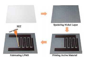
The fabrication process of the LPMS is shown in Fig. 1. A typical LPMS was fabricated in the following steps. Firstly, polyethylene terephthalate (PET) was chosen as the flexible substrate; then a thin layer of nickel was magnetron-sputtered at ambient temperature with 1 μm in thickness. Then the electrode slurry was bladed onto the substrate and dried in vacuum oven at 120 ℃ for 12 h. The thickness of the electrodewas 13μm in this work and can be tunable. Afterwards, the laser beam (wavelength: 355 nm, model: Han's Laser EP-15-DW) was used to ablate redundant parts of the CNTs/δ-MnO2 film and nickel layer to form an interdigital-electrode-structure LPMS array. In this work, the area of a single LPMS unit was controlled to be 60 mm2. The width of the interdigital fingers and the interspace between them were 300 μm and 250 μm, respectively, and these configurations can be conveniently modified.

|
Download:
|
| Fig. 1. Schematic of the electrode fabrication process. | |
The detailed characterization and electrochemical measurements were provided in the Supporting information.
The CNTs/δ-MnO2 composite was prepared by a redox reaction, where KMnO4 was used as the oxidizing agent and Mn(Ac)2 as the reducing agent. CNTs functioned as a nucleation site for the formation the MnO2 nanosheets [30]. To evaluate the electrochemical performance of CNTs/δ-MnO2 composite electrode, CV, GCD and EIS studies were conducted using a three-electrode configuration. 0.5 mol/L aqueous Na2SO4 electrolyte was used and the working potential window was selected between 0 V and 0.8 V (vs. Ag/AgCl). As is shown in Fig. S1 (Supporting information), the dramatic enhanced electrochemical performance of CNTs/δ-MnO2 composite compared with pure CNTs film is attributed to the good synergetic effect between two components. CV curves of CNTs/δ-MnO2 with varying MnO2 ratios (21.5%, 27.3%, 46.5%, 66.5%, and 81.4%) at the scan rate of 20 mV/s are presented in Fig. S2 (Supporting information). As the CNTs/δ-MnO2-41.5% showed a much better capacitance performance, the following results are presented based on this ratio. We take CNTs/δ-MnO2 as the abbreviation for the CNTs/δ-MnO2-41.5% in the following results for brief expression.
Fig. 2a illustrates the typical CV performance of the electrode with various scan rates ranging from 5 mV/s to 200 mV/s. It shows that the CV curves were relatively rectangular in shape at low scan rate, and exhibited a near mirror-image current response on voltage reversal. When the scan rate got faster, there were no significant differences in the shape of the curves, indicating a fast charge/discharge capability and effective diffusion of electrolyte in the electrode material. As is presented in Fig. 2b, the GCD curves of the CNTs/δ-MnO2 electrode at various current densities of 0.5, 1.0, 2.0, 5.0 and 10.0 A/g suggest excellent reversibility of charge storage and small voltage drop (0.05 V), which could be attributed to the high electrical conductivity of the CNTs/δ-MnO2 composite electrode, further demonstrating the excellent capacitive behaviour of the composite electrode. The calculated Cm of the CNTs/δ-MnO2 electrode as a function of current density, calculated from the GCD tests based on equation S1 (Supporting information), exhibited a maximum value of 257 F/g at the current density of 0.5 A/g.

|
Download:
|
| Fig. 2. Electrochemical characterizations of the CNTs/δ-MnO2 electrode in 0.5 mol/L aqueous Na2SO4 electrolyte: (a) CV curves of the electrode at the scan rate from 5 mV/s to 200 mV/s; (b) GCD curves of the electrode at the current densities from 0.5 A/g to 10.0 A/g; (c) cycling performance of the electrode material; (d) Nyquist curve after the first cycle. | |
While in most cases, a high Cm value (~700 F/g) could be obtained when the film of the electrode material is very thin and the material needs to be loaded onto a current collector with high surface area, which is not included when calculating the specific capacitance value. With the increase of the current density, the Cm value decreased correspondingly, but still exhibited a value of 163 F/g at the scan rate of 2 A/g, which confirmed relatively excellent rate performance of the CNTs/δ-MnO2 composite electrode.
The cycling performance of this electrode was studied by repeating the CV test at a scan rate of 100 mV/s, as shown in Fig. 2c. It is noteworthy that, the capacitance retention of CNTs/δ-MnO2 composite can still remain at 87.2% even after 4, 000 cycles, with the Cm value decreased from 257 F/g to 224 F/g, indicating excellent stability. In Fig. 2d, the frequency response analysis, in the frequency range between 10 mHz and 100 kHz with amplitude of 5 mV at an open-circuit potential, was conducted to study the alternating current impedance property of the CNTs/δ-MnO2 electrode. The charge transfer resistance (Rct), caused by Faradic reactions and the double-layer capacitance on the grain surface was extremely small. It suggests that the electrode exhibited excellent conductivity, which also contributed to the negligible voltage drop in the beginning of the GCD curve. The superior performance of the CNTs/δ-MnO2 composite can be attributed to the following three aspects [31]: 1) The interactions among the electrode composite can form a uniform porous nanostructure, which reduces the diffusion length of the ions and electrons within the electrode material; 2) The CNT with a high conductivity provides abundant transport channels for electrons; 3) The slurry dispensing process can render a face-to-face assembly of the materials, which helps provide superior electrochemical properties along the in-plane direction.
Considering the laser scribing technique is a power tool for meticulous fabrications, here it is used to fabricate thick electrodes. The symmetric LPMS can be fabricated by laser beam ablating the CNTs/δ-MnO2 electrode and the thin nickel layer (current collector) to form interdigital electrode arrays. Moreover, the theoretical energy density of the micro-supercapacitors is in direct proportion to the square of the working potential as can be seen from equation S4 (Supporting information). Hence, to develop a high performance micro-supercapacitor, the narrow working voltage window needs to be overcome by using non-aqueous electrolytes. In addition, better thermal stability of the nonaqueous electrolyte can render the LPMS resistant to the high temperature working process. Here we chose room temperature ionic liquid, [C2MIm]BF4, as the electrolyte so as to operate at a stable working voltage window of 2.0 V.
To characterize the electrochemical performance of the LPMS, Fig. 3 illustrates the CV, GCD and cycling performance of a fully packed cell unit, which shows superior capacitive characteristic and rate performance. The CV characterization of the LPMS was performed under various scan rates ranging from 10 mV/s to 100 mV/s, as shown in Fig. 3a. Calculated from equation S1 (Supporting information), Ca of the LPMS can reach to 16.0 mF/cm2, which was based on the total area of the device.

|
Download:
|
| Fig. 3. Electrochemical characterizations of the LPMS in Na2SO4 electrolyte: (a) CV curves at the scan rate from 10 mV/s to 100 mV/s; (b) GCD curves of the material at various current densities; (c) Ca values versus scanning rate calculated by GCD study; (d) Cycling performance of the LPMS. | |
The GCD test was also performed to further characterize the electrochemical performance of the LPMS device. As is shown in Fig. 3b, the IR drop calculated from the GCD curve was only 0.12 V at a current density of 0.2 A/g, by virtue of the small Ohmic contact resistance of the electrode materials. Specific capacitance of Ca values versus scanning rate calculated by CV study is shown in Fig. 3c, where it reveals that with the increase of the scan rate, the device cannot make full use of pseudocapacitance in the electrode material, the Ca value decreased accordingly. Additionally, as is shown in Fig. 3d, the LPMS was subjected to 5, 000 cycles of fulldepth charge/discharge at the scan rate of 100 mV/s, and a capacitance retention of 81.7% was obtained. The capacitance decay tendency during the continuing cycling test could be attributed to the following factor [32, 33]: The volume expansion of active materials can be induced by intercalation and transportation of electrolyte ion into the bulk material during the redox reaction.
To evaluate the performance characteristic of the LPMS device with [C2MIm]BF4 electrolyte in practical application, the energy density E and the power density P were calculated from equations S4 and S5 (Supporting information). Typical figure of merits include maximum energy density of 6.83 mWh/cm3 at power density of 154.3 mW/cm3, and of 2.71 mWh/cm3 at the maximum power density of 2557.5 mW/cm3. Compared with the devices that were tested in aqueous electrolytes [26, 34], non-aqueous electrolyte can remarkably enlarge the working potential window and optimize the energy density. As a consequence, our LPMS presents an excellent energy density and a competitive power density.
Owing to the relatively thick film of the electrode material by slurry dispensing technique, the areal capacitance of our LPMS is even better than those of the state-of-the-art thin film based ones (Table S1 in Supporting information).
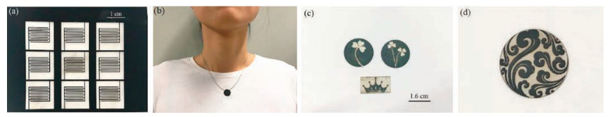
Optical images of the LPMS are shown in Fig. 4a. The planar electrode configurations could be conveniently modulated by altering the geometric parameters of the electrodes. Based on the laser processing technique, the LPMS could be fabricated in large scale precisely.

|
Download:
|
| Fig. 4. Photographic images of laser scribed electrodes with various design. (a) Several LPMSs. (b) Artistic designed LPMS with a vivid pattern of "auspicious cloud" can stick on a necklace. (c) Different electrodes patterned of "shamrocks" and "crown". (d) Magnified image of the necklace in Fig. 4b. | |
For future applications in portable micro-electronics, apart from unique functionality, the shape diversity and artistic property of devices are highly preferred. In this regard, the laser-scribing technique is probably the most flexible and versatile method to achieve high-performance micro-devices with artistic design. Particularly in this work, as shown in Fig. 4b, LPMS with a vivid pattern of "auspicious cloud" is small enough to stick on a necklace. To verify such a concept, various designs of electrodes are presented in Fig. 4c. These electrodes, showing wondrously visual and artistic property, can be further encapsulated into microsupercapacitors in a planar layout or a sandwich structure.
Here we developed a CNTs/δ-MnO2 composite-based microsupercapacitor. The CNTs/δ-MnO2 electrode was synthesized using efficient and easy-fabrication methods including solution-phase assembly and slurry dispensing technique. The conventional slurry printing technique, can not only render a face-to-face assembly of electrode material, but also fabricate a thick electrode with the significance of optimizing the performance of micro-devices. The result of electrochemical tests confirmed superior specific capacitance and long cycle life of the electrode, which could be attributed to several factors, including 3D network for the transportation of ions and electrons, good conductivity of the electrode material and superior electrochemical properties along the in-plane direction. Owing to the meticulous laser-scribing technique, the electrode can be patterned with a high resolution and made into a planar micro-supercapacitor. Last but not the least, desirably aesthetic property and shape diversity are crucial factors for the future micro-devices; the laser-scribing technique is arguably a flexible and versatile method to achieve these factors. Our work may open up opportunities for facile and delicate fabrication of energy devices with shape diversity and meaning of art. We believe that it may open a new era of the energy storage devices in future to meet the specific demand of the wearable/portable electronics.
AcknowledgmentsThis work is financially supported by the National Key Basic Research Program of China (No. 2014CB932400), the National Nature Science Foundation of China (Nos. 51607102, 51578310), China Postdoctoral Science Foundation (No. 2016M601017), Guangdong Province Science and Technology Department (Nos. 2014B090915002, 2014A010105002, 2015A030306010), and Natural Science Foundation of Guangdong Province (No. 2017A030313279).
Appendix A. Supplementary dataSupplementary data associated with this article can be found, in the online version, at https://doi.org/10.1016/j.cclet.2018.01.024.
| [1] |
N.J. Dudney, J. Li, Science 347 (2015) 131-132. DOI:10.1126/science.aaa2870 |
| [2] |
Y. Gogotsi, P. Simon, Science 334 (2011) 917-918. DOI:10.1126/science.1213003 |
| [3] |
H. Sun, L. Mei, J. Liang, Z. Zhao, X. Duan, Science 356 (2017) 599-606. DOI:10.1126/science.aam5852 |
| [4] |
Z.S. Wu, K. Parvez, X. Feng, K. Mullen, Nat. Commun. 4 (2013) 2487. |
| [5] |
Z.S. Wu, K. Parvez, A. Winter, et al., Adv. Mater. 26 (2014) 4552-4558. DOI:10.1002/adma.v26.26 |
| [6] |
C. Meng, J. Maeng, S.W.M. John, P.P. Irazoqui, Adv. Energy Mater. 4 (2014) 1301269. DOI:10.1002/aenm.201301269 |
| [7] |
J. Qin, Z.S. Wu, F. Zhou, et al., Chin. Chem. Lett. 29 (2018) 582-586. DOI:10.1016/j.cclet.2017.08.007 |
| [8] |
X. Shi, Z.S. Wu, J. Qin, et al., Adv. Mater. 29 (2017) 1703034. DOI:10.1002/adma.201703034 |
| [9] |
S. Zheng, W. Lei, J. Qin, et al., Energy Storage Mater. 10 (2018) 24-31. DOI:10.1016/j.ensm.2017.08.002 |
| [10] |
X. Zang, R. Zhang, Z. Zhen, et al., Nano Energy 40 (2017) 224-232. DOI:10.1016/j.nanoen.2017.08.026 |
| [11] |
H. Tang, C. Yang, Z. Lin, et al., Nanoscale 7 (2015) 9133-9139. DOI:10.1039/C5NR00465A |
| [12] |
B. Xie, C. Yang, ACS Nano 9 (2015) 5636-5645. DOI:10.1021/acsnano.5b00899 |
| [13] |
F. Wen, C. Hao, J. Xiang, et al., Carbon 75 (2014) 236-243. DOI:10.1016/j.carbon.2014.03.058 |
| [14] |
Z. Cai, L. Li, J. Ren, et al., J. Mater. Chem. A 1 (2013) 258-261. DOI:10.1039/C2TA00274D |
| [15] |
P. Huang, C. Lethien, S. Pinaud, K. Brousse, R. Laloo, et al., Science 351 (2016) 691-694. DOI:10.1126/science.aad3345 |
| [16] |
D. Pech, M. Brunet, H. Durou, et al., Nat. Nanotechnol. 5 (2010) 651-654. DOI:10.1038/nnano.2010.162 |
| [17] |
Y.Q. Li, X.M. Shi, X.Y. Lang, Z. Wen, J.C. Li, et al., Adv. Funct. Mater. 26 (2016) 1830-1839. DOI:10.1002/adfm.v26.11 |
| [18] |
M. Xue, Z. Xie, L. Zhang, X. Ma, X. Wu, et al., Nanoscale 3 (2011) 2703-2708. DOI:10.1039/c0nr00990c |
| [19] |
J. Feng, X. Sun, C. Wu, et al., J. Am. Chem. Soc. 133 (2011) 17832-17838. DOI:10.1021/ja207176c |
| [20] |
Z. Li, M. Shao, L. Zhou, et al., Nano Energy 20 (2016) 294-304. DOI:10.1016/j.nanoen.2015.12.030 |
| [21] |
Y. Chen, J. Xu, Y. Yang, Y. Zhao, W. Yang, et al., Electrochim. Acta 193 (2016) 199-205. DOI:10.1016/j.electacta.2016.02.021 |
| [22] |
W. Wei, X. Cui, W. Chen, D.G. Ivey, Chem. Soc. Rev. 40 (2011) 1697-1721. DOI:10.1039/C0CS00127A |
| [23] |
Y. Jin, H. Chen, M. Chen, N. Liu, Q. Li, ACS Appl. Mater. Interfaces 5 (2013) 3408-3416. DOI:10.1021/am400457x |
| [24] |
Q. Tang, M. Chen, C. Yang, et al., ACS Appl. Mater. Interfaces 7 (2015) 15303-15313. DOI:10.1021/acsami.5b03148 |
| [25] |
S. Shi, C. Xu, C. Yang, et al., Sci. Rep. 3 (2013) 2598. DOI:10.1038/srep02598 |
| [26] |
Y. Lin, Y. Gao, Z. Fan, Adv. Mater. 29 (2017) 1701736. DOI:10.1002/adma.201701736 |
| [27] |
S. Wang, Z.S. Wu, S. Zheng, et al., ACS Nano 11 (2017) 4283-4291. DOI:10.1021/acsnano.7b01390 |
| [28] |
W. Gao, N. Singh, L. Song, et al., Nat. Nanotechnol. 6 (2011) 496-500. DOI:10.1038/nnano.2011.110 |
| [29] |
S.H. Ko, H. Pan, C.P. Grigoropoulos, et al., Appl. Phys. Lett. 90 (2007) 141103. DOI:10.1063/1.2719162 |
| [30] |
Y. Wang, W. Lai, N. Wang, et al., Energy Environ. Sci. 10 (2017) 941-949. DOI:10.1039/C6EE03773A |
| [31] |
J. Yan, Z. Fan, T. Wei, et al., J. Power Sources 194 (2009) 1202-1207. DOI:10.1016/j.jpowsour.2009.06.006 |
| [32] |
Y. Gao, Y. Lin, J. Chen, et al., Nanoscale 8 (2016) 13280-13287. DOI:10.1039/C6NR03337G |
| [33] |
H. Zhao, C. Wang, R. Vellacheri, et al., Adv. Mater. 26 (2014) 7654-7659. DOI:10.1002/adma.v26.45 |
| [34] |
H. Gao, F. Xiao, C.B. Ching, H. Duan, ACS Appl. Mater. Interfaces 4 (2012) 2801-2810. DOI:10.1021/am300455d |