 2018, Vol. 29


b Key Laboratory of Advanced Energy Materials Chemistry(Ministry of Education), College of Chemistry, Nankai University, Tianjin 300071, China
Recently, there is an increasing demand for flexible energy storage systems due to the fast-growing market in portable and wearable electronics, such as roll-up displays and electric papers [1-3]. Among various energy storage devices, supercapacitors (SCs) are attracting much attention because they have high power density, long cycle lifetime, moderate energy density and wide working temperature range [4-16]. Conventional SCs usually include four main components: Current collectors, electrodes, separator, and electrolyte. In general, the separator and electrolyte are usually flexible. However, conventional SC electrodes are often fabricated by mixing active materials with conductive binders and then coating such composites onto metallic current collectors. As a result, these SC electrodes possess limited flexibility and cannot meet the demand of flexible SCs. In addition, the utilization of metallic current collectors would result in heavy configurations and low gravimetric capacitances [5, 17-25]. Therefore, the fabrication of flexible electrodes and the simplification of device configurations hold the key to the design of flexible SCs.
As a kind of typical nanocarbon material, carbon nanotubes (CNTs) have a cylindrical structure with a nanometer-scale diameter. CNTs are categorized as single-walled nanotubes (SWCNTs) and multi-walled nanotubes (MWCNTs). The MWCNTs have one or more outer tubes successively enveloping a SWCNT. The unique one-dimensional (1D) nanostructure endows individual CNTs with superior physical properties, such as a high thermal conductivity of 3500 W m-1 K-1, charge mobility of 10000 cm2 V-1 s-1, Young's modulus of 1 TPa, and theoretical specific surface area of 1315 m2/g [26-34]. Owing to the unique structure, individual CNTs can be assembled into macroscopic CNT architectures with different dimensions, including 1D fibers, 2D films, and 3D foams, which have desired mechanical and electrochemical properties [35-41]. In addition, these macroscopic CNT materials are easily handled and utilized under various conditions, making them ideal electrode materials for high performance flexible SCs.
Up to date, significant efforts have been made to fabricate various forms of CNTs-based flexible electrodes. In these work, the flexibility of SC electrodes not only means reversible bending, but also refers to stretching, compressing, and/or twisting. The versatility of CNTs-based flexible electrodes promotes the design of flexible SCs with various configurations, including flexible, stretchable and/or compressible fiber and thin film SCs. Moreover, these advanced SCs further boost the development of multifunctional integrated systems or self-powered hybrid energy systems. Here, we summarized the electrode assembly strategies, device configurations and the integrations of flexible SCs with other energy harvesting or storage systems. Furthermore, the challenges and prospects in this exciting field are discussed as well.
2. Configuration design of flexible supercapacitors 2.1. Flexible fiber supercapacitorsSince fiber SCs possess the capability of being integrated into wearable electronics and smart textiles, they have attracted significant interest [42-48]. Fiber SCs devices are shaped like 1D wires with the diameters in a range from micrometers to millimeters. Fiber SCs based on CNTs-based electrodes have two main device configurations, including twisted fiber SCs and coaxial fiber SCs [49, 50]. The twisted fiber SCs can be fabricated by twisting two fiber electrodes together with a separator or solid state electrolyte between them [49]. The twisted configuration results in the limited direct contact areas and physically detach between two fiber electrodes during bending or folding process, which degrades their electrochemical performance. Different from the twisted fiber SCs, the coaxial fiber SCs are fabricated by layerby-layer assembly of a core fiber electrode, a separator or solid state electrolyte, and an outer electrode layer [49]. The coaxial configuration provides larger and more efficient interface areas between two electrodes, making it structurally more stable during bending or folding process. But how to precisely control the layerby-layer assembly of multilayers onto fibers with small diameter and long length is still a technical challenge, which could impede the large-scale production of coaxial fiber SC devices.
The fabrication of 1D fiber electrodes with robust mechanical properties is a prerequisite for constructing fiber SCs. There are two different approaches to fabricate CNTs-based fiber electrodes: Directly synthesizing 1D freestanding CNT yarns or coating CNTs onto flexible substrates. Up to date, several methods have been used for fabricating freestanding CNT yarns, including wetspinning of CNTs from polymer or acid dispersions [51-55] and dry-spinning from CNT films [56-61] or vertically aligned CNT (VACNT) arrays [62-77].
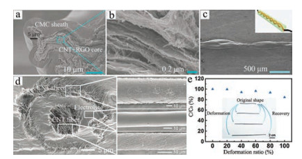
Wet-spinning has been widely used for making various organic fibers, such as acrylic, rayon, and poly(acrylonitrile) fibers. Recently, wet-spinning has been employed to produce CNTs-based fibers [51-55]. Wei's group fabricated SWCNT/chitosan (CHI) composite yarns by a wet-spinning method [55]. After hightemperature carbonization of chitosan, SWCNT/active carbon as SC electrodes showed a specific surface area of 268 m2/g and high Young's modulus of 10.9 GPa. Sodium carboxymethyl cellulose (CMC)-wrapped CNT+ reduced graphene oxide (RGO) core-sheath fibers with a high conductivity of 7000 S/m and good mechanical strength of 73–116 MPa were fabricated by a coaxial wet-spinning assembly method followed by the chemical reduction of graphene oxide (GO) into RGO. The CNT + RGO composite formed the core of the fiber and carboxymethyl cellulose (CMC) made up the sheath (Figs. 1a and b) [52]. The assembled twisted fiber SC (Fig. 1c) with CNT + RGO@CMC coaxial fibers as electrodes and polyvinyl alcohol (PVA)/H3PO4 as electrolyte showed an areal capacitance of 177 mF/cm2 and energy density of 3.84 μWh/cm2.

|
Download:
|
| Fig. 1. (a, b) Scanning electron microscopy (SEM) images of CNT + RGO@CMC coresheath fibers. (c) SEM image of side view of a twisted fiber SC. Inset shows the schematic illustration of a twisted fiber SC. Reproduced with permission [52]. Copyright 2014, Nature Publishing Group. (d) SEM images of the coaxial structure of the fiber EDLC. Reproduced with permission [68]. Copyright 2013, Wiley-VCH. (e) Dependence of specific capacitance ratio of a shape-memory fiber SC on deformation ratio. Reproduced with permission [82]. Copyright 2015, Wiley-VCH. | |
Similar to the methods employed in industrial fields to fabricate fiber materials, dry-spinning from CNT films or VACNT arrays originated from chemical vapor deposition (CVD) growth, is an effective way to fabricate 1D CNT yarns. The diameters and twisting degrees of 1D CNT yarns can be more easily controlled during the dry-spinning process [61]. The continuous 2D films through dry-drawing from VACNT arrays were passed through volatile solutions and then twisted to form 1D yarns [78, 79]. Two VACNT yarns coated with PVA/H2SO4 gel were twisted together to achieve a fiber SC, showing an areal capacitance of 2.3 mF/cm2 [65]. Since the capacitance behavior of pure VACNT yarn electrodes belongs to electrical double layer capacitors (EDLCs), which often show limited specific capacitance as well as energy density, various carbon nanomaterials including order mesoporous carbon [70] as well as graphene [64, 80], and pseudo-capacitive materials, such as MnO2 [66, 69, 77], polyaniline (PANI) [65, 71], poly(3, 4-ethylene-dioxythiophene): Poly(styrene sulfonate) (PEDOT:PSS) [81], and MoS2 [64], could be deposited onto the surface of VACNT yarns to further improve their electrochemical properties. Moreover, by combing 2D VACNT film as outer electrode and 1D VACNT yarn as inner electrode with PVA/H3PO4 electrolyte sandwiched between them, a coaxial EDLC was fabricated (Fig. 1d) [68]. The asfabricated coaxial EDLC showed an areal capacitance of 8.66 mF/cm2 with energy and power densities about 1.88 Wh/kg and 755.9 W/kg, respectively. In addition, an asymmetric coaxial fiber SC was also fabricated using the VN@carbon/CNT fiber core as the negative electrode, PVA/Na2SO4 as the solid electrolyte, and MnO2/PEDOT:PSS/CNT sheets as the positive electrode [74]. The optimized asymmetric coaxial fiber SC delivered an areal capacitance of 213.5 mF/cm2 and energy density of 96.07μWh/cm2.
The second approach to fabricate CNTs-based fiber electrodes is coating CNTs onto flexible substrates to form substrate-supported 1D fibers. The flexible substrates include metal fibers, rubber fibers, carbon microfibers, stainless steel, cotton thread, elastic fiber, shape-memory polyurethane (SMP), nylon fiber, natural cellulose fiber and so on [45, 82-90]. The unique feature of 1D substrates will endow the fiber SCs with other novel functions. For example, Peng's group has fabricated a shape-memory fiber SC with a coaxial structure by winding VACNTs on a SMP substrate [82]. The resultant fiber SCs were deformed under external stresses when the work temperature exceeded thermal transition temperature (Ttrans). The deformed shapes of SCs were maintained after being cooled down to room temperature, and recovered to the original state upon heating at a temperature high than Ttrans (Fig. 1e). The electrochemical performances of fiber SCs during deformation and recovery processes were well-maintained. Moreover, by using elastic fibers instead of SMP substrate, they also developed a coaxial and highly stretchable fiber SC [83]. The as-fabricated fiber SC delivered a specific capacitance of 19.2 F/g and remained unchanged after stretched to 75%. Furthermore, PANI was further electrodeposited onto the surface of VACNT electrodes to fabricate electrochromic and stretchable fiber SCs. The electrochromic fiber SCs were further woven into fabrics to display designed patterns [45].
2.2. Flexible thin film supercapacitorsFlexible thin film SCs recently attracted a great deal of interest for their potential applications in flexible or portable electronic systems. Flexible configuration of thin film SCs requires that the film electrode materials possess high conductivity, excellent physical flexibility, and good mechanical integrity. Macroscopic CNT films avoid the usage of conductive binders and metallic current collectors, and thus satisfy the above requirements. Macroscopic CNT films can be classified into two main types, including substrate-supported and freestanding CNT films.
CNTs are often in form of powder. After purification and functionalization, CNTs can be dissolved in solution well with the assistance of extra molecular systems such as surfactants, achieving CNT suspensions [91]. Based on CNT suspensions, many strategies, including layer-by-layer assembly [92, 93], inkjet printing [94-96], spray-coating [97-99], and dipping-drying [100-108], have been developed to assemble CNTs onto the nonconductive substrates with high flexibility, such as polyethylene terephthalate (PET) [94, 96, 109], PVA [110], diverse papers [95, 98, 100-102, 111], cotton textiles [94, 103-107, 112], and sponge [113, 114]. With the aid of the unique structure of CNTs and the van der Waals interaction between CNTs and substrates, CNTs can firmly attach onto the surface of substrates, obtaining good contact between CNTs and substrates. The 1D structure of CNTs not only ensures the high flexibility of the CNT layer formed on substrates, but also provides continuous conductive paths along the lengths of the CNTs. For example, stable SWCNT suspension could be deposited onto the PET substrate by a spray coating method to achieve flexible SWCNT film electrodes with a random and entangled network. Gel electrolyte was used as both separator and electrolyte. The flexible SWCNT film electrodes and the gel electrolyte were sandwiched to assemble flexible SC devices [109]. Moreover, several SCs could be integrated in the perpendicular and parallel directions to construct the fully printable SCs with diverse shapes [99]. However, the flexibility of such SWCNT film electrodes is limited since plastic substrates are always stiff.
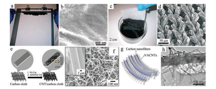
Compared to plastic substrates, flexible porous substrates would facilitate the infiltration of electrolyte ion into the electrodes and enhance the adhesion between CNTs and substrates. Cellulose fiber papers offer 3D hierarchical porous structures, light weight, as well as high flexibility, making them promising scaffolds to support CNTs. Using a simple Meyer rod coating method, SWCNT ink was coated onto the commercial papers (Figs. 2a and b) [98]. Owing to the high conductivity of SWCNTs and the strong bonding between SWCNTs and the cellulose fiber in the paper, the SWCNT coating papers display high conductive (1V/sq) and excellent flexibility, even foldability. They can be bent down to a 0.2 cm radius or folded without any change in electrical conductivity. In addition to cellulose fiber papers, cotton textiles made by weaving natural or synthetic fibers such as cotton or polyester are also used as substrates to deposit SWCNTs. With a simple "dipping and drying" process, SWCNTs were wrapped around fabric fibers to produce high conductive textiles (Figs. 2c and d) [103]. The electrical conductivity of SWCNT coating textiles was up to ~5 S/cm when the thickness of cotton sheets is ~2 mm. Furthermore, CNTs are able to coat on the surface of the sponge skeleton through the similar process, since sponges are also made up of small polyester fibers and possess highly porous structure [113]. The CNT films on these porous substrates possess high specific surface area, strong mechanical strength as well as fast mass and electron transport kinetics. Therefore, CNT coating porous substrates are promising electrodes for flexible thin film SCs.

|
Download:
|
| Fig. 2. (a) Conformably coating CNTs on commercial papers by a Meyer rod coating method. (b) SEM image of CNTs-coated commercial papers. Reproduced with permission [98]. Copyright 2009, National Academy of Sciences. (c) Conductive textiles fabricated by a "dipping and drying" process. (d) SEM image of CNTs-coated fabric sheets. Reproduced with permission [103]. Copyright 2010, American Chemical Society. (e) Schematic illustration of fabricating MWCNTs/carbon cloth composite via a CVD method. (f) SEM images of MWCNTs/carbon cloth composite. Reproduced with permission [126]. Copyright 2016, Wiley-VCH. (g) Schematic diagram and (h) TEM image of the VACNTs/carbon nanofiber composite obtained by combining electrospinning with pyrolysis technologies. Reproduced with permission [119]. Copyright 2015, American Chemical Society. | |
Apart from the nonconductive substrates as mentioned above, diverse conductive substrates, including graphite sheets [115, 116], graphene-based foams [108, 117, 118], carbon fibers [119-124], and carbon cloths [125-128], can also serve as substrates to deposit CNTs by solution-based processes such as electrostatic spraying [129], electrophoretic deposition [115, 116, 125, 130, 131] or CVD technology [117, 118, 120-124, 126-128]. These conductive substrates can act as mechanical supports and current collectors for CNTs-based flexible SC electrodes. For example, MWCNTs with a typical bamboo-like structure were directly grown onto carbon cloths by CVD process (Figs. 2e and f) [126]. In addition, helically coiled CNTs were synthesized on carbon fibers in a CVD system, which exhibit an open mesoporous nanostructure with an average pore size of 3.8 nm [122]. Furthermore, by combining electrospinning with pyrolysis technologies, VACNTs were directly grown on carbon nanofibers to form a hierarchically mesoporous nanostructure with pore size distribution in a range of 2–40 nm (Figs. 2g and h) [119]. These 3D hierarchically mesoporous structures not only provide high structural interconnectivity, large surface area as well as high conductivity, but also possess a large number of transport channels for electrons and ions. Accordingly, they exhibit an enhanced electrochemical performance for flexible thin film SC devices.
The substrate-supported pure CNT film electrodes often exhibit high power density and stable charge/discharge cycles, but low specific capacitance and energy density. Therefore, various composite materials composed of CNTs and pseudo-capacitive materials with superior specific capacitance and energy density have been widely designed. For example, to further improve the electrochemical properties of CNT coating textiles, MnO2 nanostructures were electrodeposited on the surface of CNTs in CNTs/textile composite, which remained a porous structure. The mass loading of MnO2 nanostructures is up to 8.3 mg/cm2, leading to a high areal capacitance of 2.8 F/cm2 (scan rate: 0.05 mV/s) [112]. In addition to nanostructured MnO2, PANI nanowires were also deposited onto the surface of the SWCNT/cloth composite by a dilute polymerization process [104]. Such PANI/SWCNT/cloth electrode delivered a specific capacitance of 410 F/g.
Although diverse substrates have been used to deposit CNTs to achieve flexible SC electrodes, the use of substrates would increase the weight of entire SC devices, leading to low specific capacitance. Therefore, various strategies have been employed to assemble CNTs into freestanding films, including vacuum filtration [132-157] or casting methods [158-161] of CNT solutions, CVD growth [118, 162-172], dry-drawing from VACNT arrays [173-180], and compression of CNT aerogels into films [117, 181-183].
Vacuum filtration is one of the most widely used methods to prepare freestanding CNT films based on CNT ink. In this process, CNT ink was firstly prepared by simply dispersing CNTs with surfactants in liquid solvent via a sonication process. CNT ink was then passed through a porous membrane, e.g., AAO template, leaving the solid CNTs on the membrane to form films [137]. After washing and drying, the CNT films could be gently peeled off from the membrane if the thickness of CNT films is thick enough (Figs. 3a and b) [184]. The resultant CNT films possess a continuous and random-oriented network structure (Fig. 3c). The freestanding CNT films can be used as both the current collectors and electrodes without any further treatment to fabricate flexible thin film SC devices (Fig. 3c) [185]. The specific capacitance and energy density of the as-fabricated SC device using 1 mol/L H2SO4 as electrolyte were about 39 F/g and 0.02 Wh/kg, respectively. Moreover, transparent CNT films with ultrathin thickness can also be fabricated by readily controlling the concentration and volume of the CNT ink [186-190]. A highly transparent thin film SC device with the transmittance of 82% at a wavelength of 550 nm was obtained with only 0.02 mg of SWCNTs (Fig. 3d) [189]. The corresponding specific capacitance was about 22.2 F/g. These flexible thin film SC devices based on pure CNT films show EDLC behaviors with low specific capacitance and energy density, which mainly arise from their limited specific surface area.

|
Download:
|
| Fig. 3. (a, b) Optical images of flexible CNT films fabricated by vacuum filtration process. Reproduced with permission [184]. Copyright 2010, Elsevier. (c) Schematic diagram and optical image of flexible thin film SC using CNT films as both the current collectors and electrodes. Reproduced with permission [185]. Copyright 2007, American Institute of Physics. (d) Optical image of a transparent thin film SC with 0.02 mg of SWCNTs via vacuum filtration. Reproduced with permission [189]. Copyright 2014, American Chemical Society. (e) Optical and (f) SEM images of the directly grown SWCNT films via a CVD method. Reproduced with permission [164]. Copyright 2012, Royal Society of Chemistry. (g) Optical and cross-section SEM images of freestanding epidermal SCs with the thickness of only 1 μm. Reproduced with permission [202]. Copyright 2016, Wiley-VCH. (h) Freestanding VACNT films drawn out from a VACNT array on a silicon wafer. Reproduced with permission [174]. Copyright 2010, Wiley-VCH. (i) Photographs of transparent SCs assembled in the parallel and cross configurations based on VACNT sheets. Reproduced with permission [176]. Copyright 2014, Nature Publishing Group. | |
Graphene sheets possess a higher theoretical specific surface area (2630 m2/g) compared to CNTs [191-199], and thus the combination of CNTs with graphene sheets to prepare graphene/CNT composite electrodes can take advantage of excellent conductivity from CNTs and large surface area of graphene sheets. The CNT/graphene multilayered films were fabricated by vacuumassisted self-assembly from a mixed dispersion of GO and CNTs, followed by a reduction process of GO into RGO [136, 140, 160, 190, 200]. The resultant CNT/RGO hybrid films exhibit a layered structure with CNT networks sandwiched between the RGO sheets [140]. The specific capacitances of CNT/RGO films with CNT mass ratios of 20% and 40% were about 212.9 F/g and 302.9 F/g (current density: 0.5 A/g), respectively. In addition to graphene sheets, pseudo-capacitive materials are also be combined with CNTs through vacuum filtration to form CNTs-based hybrid films with enhanced capacitance and energy density. Conductive polymers including PEDOT:PSS [154, 156], PANI [132, 157, 162], as well as polypyrrole (PPy) [149], and transition-metal oxides/nitrides/hydroxides/sulfides, such as MnO2 [133, 138, 146, 201], V2O5 [135, 169], NiCo2O4 [150], In2O3 [134, 186], WO3 [147, 152], VN [144], NiMn hydroxide [145], and MoS2 [151], are the main pseudo-capacitive materials to be incorporated into CNTs films for flexible thin SC electrodes under widely studied. For instance, using MnO2/SWCNT films as the positive electrode and In2O3/SWCNT films as the negative electrode, flexible asymmetric SCs were assembled. The optimized asymmetric SCs exhibited a specific capacitance of 184 F/g, energy density of 25.5 Wh/kg, and power density of 50.3 kW/kg [134].
CVD technology can be used to fabricate freestanding CNT films [163, 164, 171, 172, 202]. The as-grown CNT films are usually SWCNTs or double-walled nanotubes (DWCNTs) with a continuous 2D reticulate structure, where CNTs are preferentially aligned along the flow direction, forming a Y-type junction (Figs. 3e and f) [164]. The freestanding SWCNT films show a large-scale and homogeneous film with controllable thickness, providing the opportunity to tailor them into any desired shape to match the device requirement. The directly grown SWCNT films can be directly used as both electrodes and current collectors to fabricate compact SCs with a high power density of 197.3 kW/kg [163]. The transmittance of directly synthesized SWCNT films is usually about 70% at the wavelength of 550 nm. To separate the directly grown SWCNT films into ultrathin SWCNT films, a repeated halving approach has been developed [170]. Based on the ultrathin SWCNT films, flexible and transparent SC devices with the transmittance up to 60% were fabricated. In addition, epidermal SCs with the thickness of only 1 μm were also developed (Fig. 3g) [202]. To enhance the energy density of SWCNT films, PANI was electrodeposited on the surface of SWCNT bundles by in situ electrochemical polymerization, forming a continuous 'skeleton/skin' structure [164]. Flexible SCs based on SWCNT/PANI hybrid films achieved a high energy density of 131 Wh/kg.
In addition to freestanding CNT films, VACNT arrays, in which CNTs are vertically aligned and perpendicular to the substrates, are also prepared by CVD method [203-206]. By directly dry-drawing process, the vertical alignment of CNTs in the VACNT arrays can be converted into horizontal alignment along the drawing direction with end-to-end jointed connections, forming a ultrathin VACNT film (Fig. 3h) [174]. The resultant ultrathin VACNTs films possess high conductivity, excellent transmittance, and good mechanical integrity, making them promising electrode materials for flexible transparent SCs [175-177]. When a single-layer VACNT sheet on the polydimethylsiloxane (PDMS) substrate was used as the transparent electrodes, the transparent SC devices with crossover and parallel configurations (Fig. 3i) showed 75% and 64% transmittance at 550 nm, respectively [176]. Since the weight of active materials in the ultrathin electrodes is almost negligible, the energy and power densities of transparent SC devices are relatively low. As a result, PANI was deposited onto the surface of VACNT electrodes [177]. A high specific capacitance of 308.4 F/g was achieved for transparent SC devices with VACNT/PANI composite electrodes.
3D CNT aerogels with a highly interconnected porous structure can be synthesized by CVD or freeze-drying process. Compression of 3D CNT aerogels into films is also an effective and simple strategy to fabricate freestanding CNT films with porous structure [117, 181-183]. Although the pore diameter in the compressed CNT aerogel films was decreased to the nanoscale, the highly porous microstructure of 3D CNTaerogels can be largely maintained in the compressed CNT aerogel films. The highly porous nanostructure of the compressed CNT aerogel films is very helpful for increasing the absorption of the electrolytes and providing diffusion channels for electrolyte ions, thereby enhancing the performance of SC devices. Moreover, the compressed CNT aerogel films are easily scaled up and show high flexibility. For example, cellulose nanofibers (CNFs)/MWCNT hybrid aerogels were prepared from CNFs/MWCNT hydrogels by supercritical CO2 drying and then compressed into aerogel films under an external pressure. Flexible thin film SCs based on CNFs/MWCNT aerogel film electrodes exhibited a specific capacitance of 178 F/g [181]. Graphene and pseudo-capacitive materials can be easily incorporated into hydrogels to form CNTsbased hybrid aerogel films with enhanced specific capacitance and energy density [182, 183].
Flexible thin film SCs are usually constructed in a typical stack structure. This stack geometry often limits electrolyte ions diffusion from the surface of CNT electrodes into their depth, and causes insufficient utilization of the totally accessible surface area. Thus SCs with stack structure often show relatively low charge/discharge rates, along with relatively low energy and power densities. Recently, in-plane micro-supercapacitors (micro-SCs), which consist of an array of interdigitated microelectrodes with micron-scale sizes, have been developed to enhance the diffusion ability of the electrolyte ions through the open edges of the microelectrodes [207, 208]. The in-plane micro-SCs could offer ultrahigh power density that is much larger than that of conventional SCs due to their short ion diffusion length. Moreover, dozens of micro-SC devices can be easily integrated onto a chip to reduce overall chip design complexity by eliminating intricate interconnects and further increase the energy density.
Various micro-fabrication technologies have been developed to precisely control the structure of the interdigitated electrodes based on freestanding CNT films and their composites. The strategies of preparing interdigitated electrodes for micro-SCs mainly include bottom-up [209-217] and top-down approaches [218-220]. For the bottom-up approach, an electrode pattern is firstly made on a substrate using conventional photolithography technology, and then CNTs-based films are controllably deposited onto the as-prepared electrode pattern through a thin-film preparation method such as layer-by-layer assembly, CVD growth and spray coating. For example, the functionalized SWCNT microelectrode arrays fabricated by the spray coating process (Fig. 4a) exhibited a specific capacitance of 55.3 F/g [214].

|
Download:
|
| Fig. 4. (a) Schematic illustration for the fabrication of SWCNT electrode based micro-SCs on a PDMS substrate through a bottom-up approach. Reproduced with permission [214]. Copyright 2013, American Chemical Society. (b) Schematic illustration and photograph of flexible micro-SCs based on SWCNT/amorphous carbon/MnO2 hybrid electrodes through a top-down strategy. Reproduced with permission [218]. Copyright 2016, Elsevier. | |
Unlike bottom-up approach, the top-down strategy is a process of making an electrode pattern on CNTs-based thin films through an etching process. For instance, a high dense SWCNT network was grown on the catalyst-coated quartz substrate by CVD technology, and photoresist-based electrodes were then photolithographically patterned on the SWCNTs-coated substrate [218]. After the carbonization and oxygen plasma treatment, micro-SCs with interdigital SWCNT/amorphous carbon electrodes were achieved (Fig. 4b). MnO2 nanoflowers were further electrodeposited onto the interdigital SWCNT/amorphous carbon electrodes to enhance their energy density. The as-fabricated micro-SCs can be easily transferred to soft substrates and show a volumetric capacitance of 20.4 F/cm3 and cycling performance about 92.4% of the initial capacitance after 5, 000 cycles.
2.3. Stretchable supercapacitorsHighly stretchable electronics are a promising next-generation electronic technology wherein circuits are built-on or embeddedin stretchable substrates. To power such highly stretchable electronics, it is essential to develop stretchable energy storage devices. Therefore, the development of stretchable SCs with large elastic deformations and high performances are urgently needed [221, 222].
The successful fabrication of stretchable SCs is determined by the achievement of highly stretchable electrodes and configurational design of stretchable SC devices. The highly stretchable SCs require that their electrode materials should possess high stretchability, good conductivity, as well as high specific surface area. Some stretchable electrodes have been fabricated by directly assembling CNTs on some stretchable substrates such as polymers [57, 158, 176], cotton textiles [103, 223], and electrolytes [224, 225]. However, such stretchable electrodes always exhibit limited elastic deformations accompanied with low electrochemical performance, which cannot match highly stretchable electronics. In order to overcome these issues, three novel structures were developed to fabricate highly stretchable SCs, including a helical coiled fiber structure [62, 84, 226], a buckled structure [63, 67, 72, 77, 172, 177, 227-242], and an island-bridge structure [212-216].
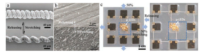
The capability of enduring a large tensile strain originates from the untwisting of the coiled fiber. The helical coiled fibers (Fig. 5a) were prepared by overtwisting several CNT fibers together with coiled loops aligning along the fiber axis [62]. The coiled loops with small diameter and pitch distance around dozens of microns endow the fiber with excellent elasticity. As a result, the helical coiled fibers are able to be gradually elongated with the CNTs remaining highly aligned during stretching process, and returned to the original coiled structure after being released (Fig. 5a). The double-helix stretchable SCs were fabricated by twisting two individual helical coiled fibers coated with a thin layer of gel electrolyte [226]. The as-fabricated double-helix stretchable SC based on CNT fiber electrodes showed a specific capacitance of 19.2 F/g and remained 94% of its original capacitance after stretched up to 150%.

|
Download:
|
| Fig. 5. (a) SEM images of a helical coiled fiber under uniaxial strain of 0 and 100%. Reproduced with permission [62]. Copyright 2014, Wiley-VCH. (b) SEM images of a buckled SWCNT film under uniaxial strain of 0 and 140%. Reproduced with permission [228]. Copyright 2013, Wiley-VCH. (c) Optical images of a micro-SC array on a deformable substrate with an island-bridge structure under biaxial strain of 0 and 50%. Reproduced with permission [213]. Copyright 2014, American Chemical Society. | |
Different from the helical coiled fiber structure, the buckled structural configuration (Fig. 5b) can accommodate large stretching strains by changing the wave amplitude and wavelength to avoid potentially destroying the active electrode materials. The buckled structure is often obtained by spreading out active electrode material on the prestrained substrate. The wave amplitude and wavelength of the resultant buckled structure are responsible for the ability of enduring strain. Smaller buckled structure can endure larger strain. The buckled structure can be applied to stretchable fiber SCs [63, 67, 72, 236-239] and thin film SCs [77, 172, 177, 227-235, 240-242]. For instance, Peng's group prepared a stretchable fiber SC with a coaxial structure based on CNT/PANI hybrid electrodes, which exhibited a specific capacitance of 111.6 F/g under a stain up to 400% [238]. Furthermore, two MnO2/CNT hybrid electrodes with microscopically buckled and macroscopically coiled structure were placed parallel to achieve a stretchable fiber SC, which exhibited a superelastic deformation up to 800% [237]. In addition to stretchable 1D CNT fibers, stretchable 2D CNT films with buckled structure (Fig. 5b) were also fabricated by combining continuous reticulate SWCNT films with pre-strained PDMS [228]. Using these buckled SWCNT films as electrodes and PVA/H2SO4 gel as both electrolyte and separator, stretchable SC devices were fabricated. The resultant SC devices exhibited a specific capacitance of 48 F/g, which remained nearly unchanged under 120% strain even in the stretching process. The specific capacitance of stretchable SWCNT electrodes can be further improved by adding nanostructured pseudo-capacitive materials, such as MoS2 [233]. Furthermore, the buckled structure can be used not only in a single direction to produce uniaxial stretchability, but also in two directions to produce biaxial stretchability, leading to the enhanced stretchability with more complex buckled structures [231, 240].
Another important structural design for achieving high stretchability is an island-bridge structure. In an island-bridge design, islands are composed of the electrode materials strongly bonded to the stretchable substrates, which can be isolated from the external strain during the stretching process. Bridges are made up of interconnects with high flexibility and conductivity, providing the major stretchability. For example, Ha's group fabricated a biaxially stretchable micro-SC array on a deformable substrate (Fig. 5c) [213]. The deformable substrate was soft elastomer of Ecoflex film with locally implanted stiff PET film and embedded liquid metal interconnection. The micro-SC array fabricated by MWCNT interdigitated electrodes and ionogel electrolyte was dry-transferred onto the surface of Ecoflex film with PET films implanted to form island region. The liquid metal interconnection embedded in the Ecoflex film was used to connect the micro-SC array in series and parallel, which can endure large strains to form bridge region. The maximum strain applied to micro-SC array in the island region was only smaller than 0.02%, while that on the Ecoflex film was larger than 250% under uniaxial strain of 70% and biaxial strain of 50% (Fig. 5c).
2.4. Compressible supercapacitorsIn addition to 1D fibers and 2D films, CNTs can also be used as the building blocks to fabricate porous CNT foams with highly interconnected structure and large compressibility. Such 3D macroporous CNT foams are the ideal electrodes of compressible SCs since they can retain their high electronic and ionic conductivity under large compression deformation. Many strategies have been used to fabricate 3D compressible CNT foams, including the template-directed synthesis [243-248], self-assembly from solvent dispersions [249], and coating CNTs on the compressible substrates [250, 251].
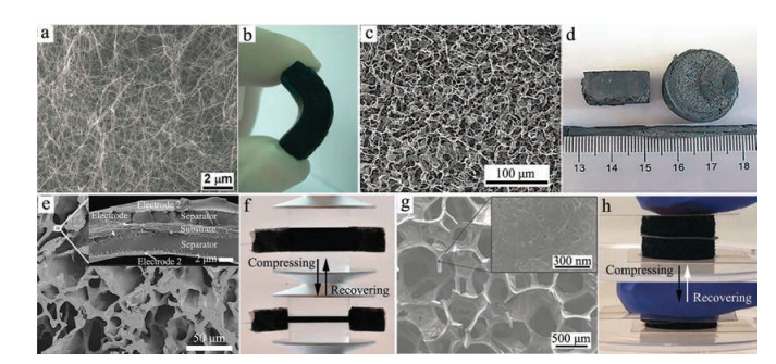
The template-directed synthesis based on CVD technology has been employed to fabricate 3D CNT foams with diverse microstructures [203, 243-244]. The CNT foams were often made up of porous and randomly interconnected CNT skeletons (Figs. 6a and b) [243]. They exhibited a complete volume recovery at a strain of 60%, which is attributed to the squeezing of inter-tube pores. Since the 3D pure CNT foams as compressible SC electrodes always exhibit low energy density, pseudo-capacitive materials are often incorporated into the 3D CNT foams to further improve their electrochemical performance [245-248].

|
Download:
|
| Fig. 6. (a) SEM and (b) optical images of CNT foams with a porous morphology obtained by CVD technology. Reproduced with permission [243]. Copyright 2010, Wiley-VCH. (c) SEM and (d) optical images of CNT/RGO aerogels with an interconnected and porous structure. Reproduced with permission [249]. Copyright 2013, Wiley-VCH. (e) SEM images of compressible SCs by layer-by-layer assembling SWCNTs/PEI as electrodes and PEI/PAA film as separator on the skeleton of sponge. (f) Optical images of the asfabricated compressible SC during the compressing and recovering processes. Reproduced with permission [250]. Copyright 2015, Nature Publishing Group. (g) SEM images of the nanostructured PANI/SWCNTs/sponge electrodes. (h) Optical images of the resultant compressible SC based on PANI/SWCNTs/sponge electrodes and PVA/H2SO4 gel electrolyte during the compressing and recovering processes. Reproduced with permission [251]. Copyright 2015, Wiley-VCH. | |
Ultra-flyweight CNT/RGO aerogels with an interconnected and porous 3D framework (Fig. 6c) could be fabricated by freeze-drying CNT/GO mixed aqueous solutions, followed by chemical reduction of GO into RGO [249]. The CNT/RGO aerogels with desired densities and shapes were easily manufactured in a large scale (Fig. 6d). The as-fabricated CNT/RGO aerogels exhibited an elasticity-responsive conductivity and large compressible deformation up to 82%, which were ascribed to the synergistic effect between CNT ribs and RGO cell walls.
Coating CNTs on the compressible substrates is also a strategy to fabricate 3D compressible CNTs-based electrodes. Sponges as an ideal compressible substrate consist of many small cellulose or polyester fibers with an interconnected and porous network structure. The CNTs/sponge composite materials as compressible SC electrodes combine the reversible compressibility of sponges and high conductivity of CNTs. Compressible SC devices were designed by layer-by-layer assembling COOH-functionalized SWCNTs/cationic polyethyleneimine (PEI) as electrodes and PEI/polyacrylic acid (PAA) multilayer film as the separator on the skeleton of the sponge (Figs. 6e and f) [250]. Moreover, the CNTs/sponge electrodes with rough surface and porous structure are also a promising scaffold to deposit pseudo-capacitive materials for further improvement of electrochemical performance. Nanostructured PANI/SWCNTs/sponge electrodes (Fig. 6g) were fabricated through assembling SWCNTs onto the skeleton of sponge using CNT ink, followed by depositing PANI onto the surface of SWCNTs via chemical polymerization [251]. Highly compressible SCs with integrated configuration (Fig. 6h) were fabricated using PANI/SWCNTs/sponge as electrodes and PVA/H2SO4 as electrolyte. The specific capacitance of resultant compressible SCs was about 216 F/g and lost 3% under compressible strain up to 60%.
3. Integrating CNTs-based SCs with multifunctional devicesRecently, great efforts have been made in designing deformation-tolerant electronic devices with various functions such as transistors, photodetectors, and light-emitting diodes [252-259]. However, most of these electronic devices are often powered by external power sources, which are bulky and not flexible. The usage of these external power sources not only increases the weight of the electronic system, but also severely limits their flexibility. To achieve fully flexible integrated electronics, as an essential component of electronics, the power source units have to possess the ability to endure large deformation without degrading their performance. As discussed above, many flexible SCs with large deformation and good electrochemical performance have been fabricated by various strategies. However, these flexible SCs are usually operated independently with other electronic devices, leading to some extra space and energy consumption due to the external connection [191]. Integrating flexible SCs with other electronic devices together would propel the electronic system into compact and lightweight configurations. Therefore, considerable research efforts have been made to integrate flexible SCs with different functional electronic devices into a multifunctional system.
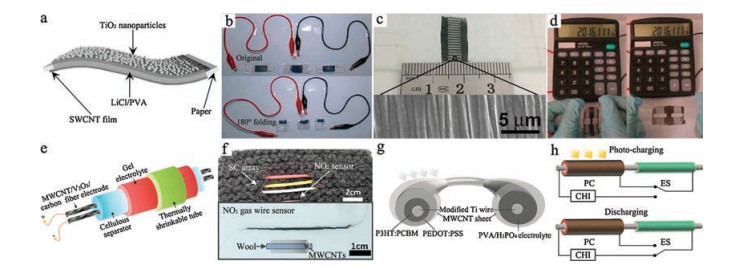
The photodetectors, which can convert light into electrical signal, can be used in various fields, such as environmental monitoring as well as sensors [260-274]. SC/photodetector integrated devices have been designed in fiber-shaped and micro-structured configurations [275-277]. However, these reported integrated SC/photodetector systems display limited flexibility due to the limitation of electrode materials and device configurations. To enhance the flexibility of the integrated systems, foldable all-solid-state SC/photodetector systems were rationally designed into a simplified and compact configuration (Figs. 7a and b) [278]. In this integrated system, SWCNT films on both side of paper acted as SC electrodes and PVA/LiCl gel served as electrolyte. TiO2 nanoparticles were coated onto the surface of either SWCNT film electrode to function as the work electrode of photodetector. The integrated devices exhibit a specific capacitance of 28 F/g and a sensitivity of 24.7 corresponding to a photocurrent of 1.78 μA for white-light detection. Furthermore, the all-solid-state integrated configuration endows the system with stable capacitance and photodetection behaviors even folded by 180° (Fig. 7b). In addition, by combining both laser-scribing and transferring processes, the stretchable SWCNT micro-electrodes with a buckled structure on the PDMS substrate were obtained (Fig. 7c) [279]. To endow the devices with photodetection function, TiO2 nanoparticles were coated onto the surface of SWCNT micro-electrodes. The asfabricated integrated systems can still remained the stable capacitance performance and photocurrent response even when they were stretched up to 200% (Fig. 7d).

|
Download:
|
| Fig. 7. (a) Schematic diagram and (b) optical image of foldable SC/photodetector integrated devices. Reproduced with permission [278]. Copyright 2017, Wiley-VCH. (c) Optical image of a stretchable micro-SC/photodetector integrated device based on the TiO2-coated buckled SWCNT film electrodes. (d) Optical images of the stretchable micro-SC/photodetector integrated devices under 0 and 200% strains. Reproduced with permission [279]. Copyright 2017, Elsevier. (e) Schematic diagram of a fiber SC device using MWCNT/V2O5/carbon fiber as electrodes and cellulose as separator. (f) Optical image of integrating wire-shaped NO2 gas sensor with fiber SC array on fabric. Reproduced with permission [280]. Copyright 2017, Elsevier. (g) Schematic illustration of a flexible "energy fiber" system with integrated structure of solar cell and SC. (h) Schematic diagram of the circuit connection state of "energy fiber" during the charging and discharging process. Reproduced with permission [283]. Copyright 2014, WileyVCH. | |
As part of a safety system, gas detectors can detect the presence of diverse harmful gases in an area. Accompanied by the increasing environment pollution, flexible and wearable gas sensors for health or environmental monitoring have attracted considerable attention [280, 281]. Fiber SCs integrated with wire-type NO2 sensors were knitted on textile (Fig. 7f) [280]. In such integrated system, fiber SCs were fabricated using MWCNT/V2O5/carbon fiber as electrodes and cellulose as separator (Fig. 7e), which exhibited an areal capacitance of 10.6 mF/cm2 at a current density of 0.5 mA/cm2. The wire-type NO2 sensors were composed of MWCNTs/wool wire, which formed NO2- on the surface of MWCNTs and led to the current increase when exposed to NO2 gas. The as-fabricated wire-type NO2 sensors exhibited a current of around 35 nA upon exposure to 200 ppm NO2 gas, and worked stably for 400 s with three fiber SCs connected in parallel.
Since solar cells can directly convert the light into electricity, the SC/solar cell integrated system can realize the photovoltaic conversion and energy storage simultaneously to become a selfpowered energy system [282-285]. A flexible "energy fiber" system was presented by combining the polymer solar cell with electrochemical SC device (Fig. 7g) [283]. The resultant "energy fiber" in the solar cell part is composed of MWCNT/PEDOT:PSS/poly(3-hexylthiophene):-phenyl-C61-butyric acid methyl ester (P3HT:PCBM)/titania nanotube-modified Ti wires, which delivered an energy conversion efficiency about 1.01% when exposed to sunlight. The "energy fiber" in the SC part employed titania nanotube-modified Ti wires and MWCNT sheets as two electrodes, which store solar energy upon exposure to sunlight and released the energy stored after removing sunlight (Fig. 7h). The energy storage efficiency in the SC part and the entire "energy fiber" are about 65.6% and 0.82%, respectively. The as-fabricated "energy fibers" can be easily woven with each other or with other chemical fibers to form flexible textiles.
4. Summary and outlookThis review summarized the recent progress in the electrode preparation and configuration design of flexible SCs based on the macroscopic CNTs-based materials and their integration with other functional electronic devices. The macroscopic CNTs-based materials, including 1D fibers, 2D films, and 3D foams, were highlighted. Using macroscopic CNTs-based composite materials as electrodes, flexible, stretchable and/or compressible fiber and thin film SC configurations, were designed. They exhibited superior electrochemical performance, excellent physical flexibility, and light weight. Some attempts to integrate flexible SCs with different functional electronic devices into a multifunctional system have also been introduced to show the prospects of flexible SCs.
Although aforementioned great progress has been made, many challenges still exist and need to be overcome. For instance, flexible SCs strongly rely on the material design of macroscopic CNT electrodes. It is still a great challenge to realize effective utilization of the superior properties of individual CNTs and explore novel functions beyond individual CNTs in the macroscopic CNT architectures. The combination of suitable pores, large surface area, high conductivity and good mechanical properties is indispensable for macroscopic CNTs-based flexible SCs to pursuit superior electrochemical performance. In addition, the incorporation of pseudo-capacitive materials into macroscopic CNT electrodes can enhance the specific capacitance and energy density, but degrade their power density and cycling stability. Controllable interaction between CNTs and pseudo-capacitive materials in the composite architectures is required to achieve the synergistic effect. To realize the integration of flexible SCs with other electric devices, novel SC configurations need to be designed to match corresponding electric devices. The related components, such as electrolytes and separators, need to be further explored and endowed with specific functions so as to satisfy novel SC configurations.
AcknowledgmentsThis work was supported by the MOST (Ministry of Science and Technology of China) (No. 2017YFA0206701), NSFC (National Natural Science Foundation of China) (Nos. 51602218, 21573116, 11604242), MOE (Ministry of Education of China) (No. B12015), and Tianjin Basic and High-Tech Development (No. 15JCYBJC17300). Z. Niu thanks the recruitment program of global experts.
| [1] |
S.R. Forrest, Nature 428 (2004) 911-918. DOI:10.1038/nature02498 |
| [2] |
D.Y. Khang, H.Q. Jiang, Y. Huang, J.A. Rogers, Science 311 (2006) 208-212. DOI:10.1126/science.1121401 |
| [3] |
J.A. Rogers, T. Someya, Y.G. Huang, Science 327 (2010) 1603-1607. DOI:10.1126/science.1182383 |
| [4] |
M. Winter, R.J. Brodd, Chem. Rev. 104 (2004) 4245-4269. DOI:10.1021/cr020730k |
| [5] |
P. Simon, Y. Gogotsi, Nat. Mater. 7 (2008) 845-854. DOI:10.1038/nmat2297 |
| [6] |
J. Chen, F.Y. Cheng, Acc. Chem. Res. 42 (2009) 713-723. DOI:10.1021/ar800229g |
| [7] |
L.L. Zhang, X.S. Zhao, Chem. Soc. Rev. 38 (2009) 2520-2531. DOI:10.1039/b813846j |
| [8] |
D. Pech, M. Brunet, H. Durou, et al., Nat. Nanotechnol. 5 (2010) 651-654. DOI:10.1038/nnano.2010.162 |
| [9] |
Y.W. Zhu, S. Murali, M.D. Stoller, et al., Science 332 (2011) 1537-1541. DOI:10.1126/science.1200770 |
| [10] |
X.Y. Lang, A. Hirata, T. Fujita, M.W. Chen, Nat. Nanotechnol. 6 (2011) 232-236. DOI:10.1038/nnano.2011.13 |
| [11] |
F.Y. Cheng, J. Chen, Chem. Soc. Rev. 41 (2012) 2172-2192. DOI:10.1039/c1cs15228a |
| [12] |
X. Peng, L.L. Peng, C.Z. Wu, Y. Xie, Chem. Soc. Rev. 43 (2014) 3303-3323. DOI:10.1039/c3cs60407a |
| [13] |
C. Zhong, Y.D. Deng, W.B. Hu, et al., Chem. Soc. Rev. 44 (2015) 7484-7539. DOI:10.1039/C5CS00303B |
| [14] |
M. Acerce, D. Voiry, M. Chhowalla, Nat. Nanotechnol. 10 (2015) 313-318. DOI:10.1038/nnano.2015.40 |
| [15] |
M.D. Stoller, R.S. Ruoff, Energy Environ. Sci. 3 (2010) 1294-1301. DOI:10.1039/c0ee00074d |
| [16] |
C. Zhang, W. Lv, Y. Tao, Q.H. Yang, Energy Environ. Sci. 8 (2015) 1390-1403. DOI:10.1039/C5EE00389J |
| [17] |
Y. Zhang, H. Feng, X.B. Wu, et al., Int. J. Hydrogen Energy 34 (2009) 4889-4899. DOI:10.1016/j.ijhydene.2009.04.005 |
| [18] |
A.S. Arico, P. Bruce, B. Scrosati, J.M. Tarascon, W. Van Schalkwijk, Nat. Mater. 4 (2005) 366-377. DOI:10.1038/nmat1368 |
| [19] |
A. Ghosh, Y.H. Lee, ChemSusChem 5 (2012) 480-499. DOI:10.1002/cssc.v5.3 |
| [20] |
F. Beguin, V. Presser, A. Balducci, E. Frackowiak, Adv. Mater. 26 (2014) 2219-2251. DOI:10.1002/adma.v26.14 |
| [21] |
M. Sevilla, R. Mokaya, Energy Environ. Sci. 7 (2014) 1250-1280. DOI:10.1039/C3EE43525C |
| [22] |
G.P. Wang, L. Zhang, J.J. Zhang, Chem. Soc. Rev. 41 (2012) 797-828. DOI:10.1039/C1CS15060J |
| [23] |
X.Y. Zheng, W. Lv, Y. Tao, et al., Chem. Mater. 26 (2014) 6896-6903. DOI:10.1021/cm503845q |
| [24] |
Z.J. Li, W. Lv, C. Zhang, et al., Carbon 92 (2015) 11-14. DOI:10.1016/j.carbon.2015.02.054 |
| [25] |
Z. Chen, V. Augustyn, X.L. Jia, et al., ACS Nano 6 (2012) 4319-4327. DOI:10.1021/nn300920e |
| [26] |
M.F. Yu, O. Lourie, M.J. Dyer, et al., Science 287 (2000) 637-640. DOI:10.1126/science.287.5453.637 |
| [27] |
S. Hong, S. Myung, Nat. Nanotechnol. 2 (2007) 207-208. DOI:10.1038/nnano.2007.89 |
| [28] |
P. Avouris, Z. Chen, V. Perebeinos, Nat. Nanotechnol. 2 (2007) 605-615. DOI:10.1038/nnano.2007.300 |
| [29] |
M.F. Yu, B.S. Files, S. Arepalli, R.S. Ruoff, Phys. Rev. Lett. 84 (2000) 5552-5555. DOI:10.1103/PhysRevLett.84.5552 |
| [30] |
X.J. Zhou, J.Y. Park, S.M. Huang, J. Liu, P.L. McEuen, Phys. Rev. Lett. 95 (2005) 146805. DOI:10.1103/PhysRevLett.95.146805 |
| [31] |
E. Pop, D. Mann, Q. Wang, K.E. Goodson, H.J. Dai, Nano Lett. 6 (2006) 96-100. DOI:10.1021/nl052145f |
| [32] |
H. Huang, C.H. Liu, Y. Wu, S.S. Fan, Adv. Mater. 17 (2005) 1652-1656. DOI:10.1002/(ISSN)1521-4095 |
| [33] |
A. Peigney, C. Laurent, E. Flahaut, R.R. Bacsa, A. Rousset, Carbon 39 (2001) 507-514. DOI:10.1016/S0008-6223(00)00155-X |
| [34] |
K. Kordas, G. Toth, P. Moilanen, et al., Appl. Phys. Lett. 90 (2007) 123105. DOI:10.1063/1.2714281 |
| [35] |
L.Q. Liu, W.J. Ma, Z. Zhang, Small 7 (2011) 1504-1520. DOI:10.1002/smll.v7.11 |
| [36] |
H.Y. Chen, S. Zeng, M.H. Chen, Y.Y. Zhang, Q.W. Li, Carbon 92 (2015) 271-296. DOI:10.1016/j.carbon.2015.04.010 |
| [37] |
Z.Q. Niu, L.L. Liu, L. Zhang, et al., Adv. Energy Mater. 5 (2015) 1500677. DOI:10.1002/aenm.201500677 |
| [38] |
S. Nardecchia, D. Carriazo, M.L. Ferrer, M.C. Gutierrez, F. del Monte, Chem. Soc. Rev. 42 (2013) 794-830. DOI:10.1039/C2CS35353A |
| [39] |
S.H. Lee, D.H. Lee, W.J. Lee, S.O. Kim, Adv. Funct. Mater. 21 (2011) 1338-1354. DOI:10.1002/adfm.v21.8 |
| [40] |
Y.H. Wang, J.R. Zeng, J. Li, et al., J. Mater. Chem. A 3 (2015) 16382-16392. DOI:10.1039/C5TA03467A |
| [41] |
Z.Y. Cao, B.Q. Wei, Energy Environ. Sci. 6 (2013) 3183-3201. DOI:10.1039/C3EE42261E |
| [42] |
T.C. Zhang, C.H.J. Kim, Y.W. Cheng, et al., Nanoscale 7 (2015) 3285-3291. DOI:10.1039/C4NR06812B |
| [43] |
S.W. Pan, H.J. Lin, J. Deng, et al., Adv. Energy Mater. 5 (2015) 1401438. DOI:10.1002/aenm.201401438 |
| [44] |
Q.Y. Niu, K.Z. Gao, Z.Q. Shao, Nanoscale 6 (2014) 4083-4088. DOI:10.1039/c3nr05929d |
| [45] |
X.L. Chen, H.J. Lin, J. Deng, et al., Adv. Mater. 26 (2014) 8126-8132. DOI:10.1002/adma.201403243 |
| [46] |
K. Jost, D. Stenger, C.R. Perez, et al., Energy Environ. Sci. 6 (2013) 2698-2705. DOI:10.1039/c3ee40515j |
| [47] |
Y. Zheng, Y.B. Yang, S.S. Chen, Q. Yuan, CrystEngComm 18 (2016) 4218-4235. DOI:10.1039/C5CE02510A |
| [48] |
X. Cai, M. Peng, X. Yu, Y.P. Fu, D.C. Zou, J. Mater. Chem. C 2 (2014) 1184-1200. |
| [49] |
L.L. Liu, Z.Q. Niu, J. Chen, Chem. Soc. Rev. 45 (2016) 4340-4363. DOI:10.1039/C6CS00041J |
| [50] |
D.S. Yu, Q.H. Qian, L. Wei, et al., Chem. Soc. Rev. 44 (2015) 647-662. DOI:10.1039/C4CS00286E |
| [51] |
S.R. Shin, C.K. Lee, I. So, et al., Adv. Mater. 20 (2008) 466-470. DOI:10.1002/(ISSN)1521-4095 |
| [52] |
L. Kou, T.Q. Huang, B.N. Zheng, et al., Nat. Commun. 5 (2014) 3754. |
| [53] |
Y.W. Ma, P. Li, J.W. Sedloff, et al., ACS Nano 9 (2015) 1352-1359. DOI:10.1021/nn505412v |
| [54] |
Q.H. Meng, K. Wang, W. Guo, et al., Small 10 (2014) 3187-3193. DOI:10.1002/smll.v10.15 |
| [55] |
Q.H. Meng, H.P. Wu, Y.N. Meng, et al., Adv. Mater. 26 (2014) 4100-4106. DOI:10.1002/adma.v26.24 |
| [56] |
N. Zhang, W.Y. Zhou, Q. Zhang, et al., Nanoscale 7 (2015) 12492-12497. DOI:10.1039/C5NR03027G |
| [57] |
F.M. Guo, R.Q. Xu, X. Cui, et al., J. Mater. Chem. A 4 (2016) 9311-9318. DOI:10.1039/C6TA02437H |
| [58] |
R.Q. Xu, F.M. Guo, X. Cui, et al., J. Mater. Chem. A 3 (2015) 22353-22360. DOI:10.1039/C5TA06165B |
| [59] |
Y. Zhou, X.Y. Hu, Y.Y. Shang, et al., RSC Adv. 6 (2016) 62062-62070. DOI:10.1039/C6RA07297F |
| [60] |
R.Q. Xu, J.Q. Wei, F.M. Guo, et al., RSC Adv. 5 (2015) 22015-22021. DOI:10.1039/C5RA01917F |
| [61] |
W.J. Ma, L.Q. Liu, R. Yang, et al., Adv. Mater. 21 (2009) 603-608. DOI:10.1002/adma.200801335 |
| [62] |
Y. Zhang, W.Y. Bai, X.L. Cheng, et al., Angew. Chem. Int. Ed. 53 (2014) 14564-14568. DOI:10.1002/anie.201409366 |
| [63] |
T. Chen, R. Hao, H.S. Peng, L.M. Dai, Angew. Chem. Int. Ed. 54 (2015) 618-622. |
| [64] |
G.Z. Sun, X. Zhang, R.Z. Lin, et al., Angew. Chem. Int. Ed. 54 (2015) 4651-4656. DOI:10.1002/anie.201411533 |
| [65] |
K. Wang, Q.H. Meng, Y.J. Zhang, Z.X. Wei, M.H. Miao, Adv. Mater. 25 (2013) 1494-1498. DOI:10.1002/adma.v25.10 |
| [66] |
J. Ren, L. Li, C. Chen, et al., Adv. Mater. 25 (2013) 1155-1159. DOI:10.1002/adma.201203445 |
| [67] |
P. Xu, T.L. Gu, Z.Y. Cao, et al., Adv. Energy Mater. 4 (2014) 1300759. DOI:10.1002/aenm.201300759 |
| [68] |
X.L. Chen, L.B. Qiu, J. Ren, et al., Adv. Mater. 25 (2013) 6436-6441. DOI:10.1002/adma.v25.44 |
| [69] |
C. Choi, J.A. Lee, A.Y. Choi, et al., Adv. Mater. 26 (2014) 2059-2065. DOI:10.1002/adma.201304736 |
| [70] |
J. Ren, W.Y. Bai, G.Z. Guan, Y. Zhang, H.S. Peng, Adv. Mater. 25 (2013) 5965-5970. DOI:10.1002/adma.201302498 |
| [71] |
Z.B. Cai, L. Li, J. Ren, et al., J. Mater. Chem. A 1 (2013) 258-261. DOI:10.1039/C2TA00274D |
| [72] |
J. Xu, J.N. Ding, X.S. Zhou, et al., J. Power Sources 340 (2017) 302-308. DOI:10.1016/j.jpowsour.2016.11.085 |
| [73] |
F.H. Su, M.H. Miao, H.T. Niu, Z.X. Wei, ACS Appl. Mater. Interfaces 6 (2014) 2553-2560. DOI:10.1021/am404967x |
| [74] |
Q.C. Zhang, X.N. Wang, Z.H. Pan, et al., Nano Lett. 17 (2017) 2719-2726. DOI:10.1021/acs.nanolett.7b00854 |
| [75] |
X.B. Zhang, K.L. Jiang, C. Teng, et al., Adv. Mater. 18 (2006) 1505-1510. DOI:10.1002/(ISSN)1521-4095 |
| [76] |
K. Liu, Y.H. Sun, R.F. Zhou, et al., Nanotechnology 21 (2010) 045708. DOI:10.1088/0957-4484/21/4/045708 |
| [77] |
M.Y. Li, M. Zu, J.S. Yu, H.F. Cheng, Q.W. Li, Small 13 (2017) 1602994. DOI:10.1002/smll.v13.12 |
| [78] |
K.L. Jiang, Q.Q. Li, S.S. Fan, Nature 419 (2002) 801-801. DOI:10.1038/419801a |
| [79] |
K.L. Jiang, J.P. Wang, Q.Q. Li, et al., Adv. Mater. 23 (2011) 1154-1161. DOI:10.1002/adma.201003989 |
| [80] |
H. Sun, X. You, J. Deng, et al., Adv. Mater. 26 (2014) 2868-2873. DOI:10.1002/adma.v26.18 |
| [81] |
J.A. Lee, M.K. Shin, S.H. Kim, et al., Nat. Commun. 4 (2013) 1970. |
| [82] |
J. Deng, Y. Zhang, Y. Zhao, et al., Angew. Chem. Int. Ed. 54 (2015) 15419-15423. DOI:10.1002/anie.201508293 |
| [83] |
Z.B. Yang, J. Deng, X.L. Chen, J. Ren, H.S. Peng, Angew. Chem. Int. Ed. 52 (2013) 13453-13457. DOI:10.1002/anie.201307619 |
| [84] |
C. Choi, S.H. Kim, H.J. Sim, et al., Sci. Rep. 5 (2015) 9387. DOI:10.1038/srep09387 |
| [85] |
F.H. Su, X.M. Lyu, C.S. Liu, M.H. Miao, Electrochim. Acta 215 (2016) 535-542. DOI:10.1016/j.electacta.2016.08.140 |
| [86] |
V.T. Le, H. Kim, A. Ghosh, et al., ACS Nano 7 (2013) 5940-5947. DOI:10.1021/nn4016345 |
| [87] |
D.H. Zhang, M.H. Miao, H.T. Niu, Z.X. Wei, ACS Nano 8 (2014) 4571-4579. DOI:10.1021/nn5001386 |
| [88] |
N.S. Liu, W.Z. Ma, J.Y. Tao, et al., Adv. Mater. 25 (2013) 4925-4931. DOI:10.1002/adma.201301311 |
| [89] |
Z. Gui, H.L. Zhu, E. Gillette, et al., ACS Nano 7 (2013) 6037-6046. DOI:10.1021/nn401818t |
| [90] |
M.J. Shi, C. Yang, X.F. Song, et al., Chem. Eng. J. 322 (2017) 538-545. DOI:10.1016/j.cej.2017.04.065 |
| [91] |
K.F. Fu, Y.P. Sun, J. Nanosci. Nanotechnol. 3 (2003) 351-364. DOI:10.1166/jnn.2003.225 |
| [92] |
J.H. Rouse, P.T. Lillehei, Nano Lett. 3 (2003) 59-62. DOI:10.1021/nl025780j |
| [93] |
M.N. Zhang, L. Su, L.Q. Mao, Carbon 44 (2006) 276-283. DOI:10.1016/j.carbon.2005.07.021 |
| [94] |
P. Chen, H.T. Chen, J. Qiu, C.W. Zhou, Nano Res. 3 (2010) 594-603. DOI:10.1007/s12274-010-0020-x |
| [95] |
S.L. Wang, N.S. Liu, J.Y. Tao, et al., J. Mater. Chem. A 3 (2015) 2407-2413. DOI:10.1039/C4TA05625F |
| [96] |
S.K. Ujjain, P. Ahuja, R. Bhatia, P. Attri, Mater. Res. Bull. 83 (2016) 167-171. DOI:10.1016/j.materresbull.2016.06.006 |
| [97] |
A.K. Sundramoorthy, Y.C. Wang, S. Gunasekaran, Nano Res. 8 (2015) 3430-3445. DOI:10.1007/s12274-015-0880-1 |
| [98] |
L.B. Hu, J.W. Choi, Y. Yang, et al., Proc. Natl. Acad. Sci. U. S. A. 106 (2009) 21490-21494. DOI:10.1073/pnas.0908858106 |
| [99] |
X.Y. Wang, Q.Q. Lu, C. Chen, et al., ACS Appl. Mater. Interfaces 9 (2017) 28612-28619. DOI:10.1021/acsami.7b08833 |
| [100] |
Y.J. Kang, B. Kim, H. Chung, W. Kim, Synth. Met. 160 (2010) 2510-2514. DOI:10.1016/j.synthmet.2010.09.036 |
| [101] |
Y.J. Kang, H. Chung, C.H. Han, W. Kim, Nanotechnology 23 (2012) 065401. DOI:10.1088/0957-4484/23/6/065401 |
| [102] |
Z.S. Zhang, W. Wang, C. Li, et al., J. Power Sources 248 (2014) 1248-1255. DOI:10.1016/j.jpowsour.2013.10.061 |
| [103] |
L.B. Hu, M. Pasta, F. La Mantia, et al., Nano Lett. 10 (2010) 708-714. DOI:10.1021/nl903949m |
| [104] |
K. Wang, P. Zhao, X.M. Zhou, et al., J. Mater. Chem. 21 (2011) 16373-16378. DOI:10.1039/c1jm13722k |
| [105] |
W.Y. Ko, Y.F. Chen, K.M. Lu, K.J. Lin, Sci. Rep. 6 (2016) 18887. DOI:10.1038/srep18887 |
| [106] |
C.H. Liu, Z.S. Cai, Y.P. Zhao, H. Zhao, F.Y. Ge, Cellulose 23 (2016) 637-648. DOI:10.1007/s10570-015-0795-8 |
| [107] |
S. Hu, R. Rajamani, X. Yu, Appl. Phys. Lett. 100 (2012) 104103. DOI:10.1063/1.3691948 |
| [108] |
Z.Y. Zhang, F. Xiao, L.H. Qian, et al., Adv. Energy Mater. 4 (2014) 1400064. DOI:10.1002/aenm.201400064 |
| [109] |
M. Kaempgen, C.K. Chan, J. Ma, Y. Cui, G. Gruner, Nano Lett. 9 (2009) 1872-1876. DOI:10.1021/nl8038579 |
| [110] |
Q. Liu, M.H. Nayfeh, S.T. Yau, J. Power Sources 195 (2010) 7480-7483. DOI:10.1016/j.jpowsour.2010.06.002 |
| [111] |
X.D. Zhang, Z.Y. Lin, B. Chen, et al., J. Mater. Chem. A 1 (2013) 5835-5839. DOI:10.1039/c3ta10827a |
| [112] |
L.B. Hu, W. Chen, X. Xie, et al., ACS Nano 5 (2011) 8904-8913. DOI:10.1021/nn203085j |
| [113] |
W. Chen, R.B. Rakhi, L.B. Hu, et al., Nano Lett. 11 (2011) 5165-5172. DOI:10.1021/nl2023433 |
| [114] |
X. Xie, M. Ye, L.B. Hu, et al., Energy Environ. Sci. 5 (2012) 5265-5270. DOI:10.1039/C1EE02122B |
| [115] |
J.H. Zhang, Y.H. Wang, J.B. Zang, et al., Carbon 50 (2012) 5196-5202. DOI:10.1016/j.carbon.2012.07.002 |
| [116] |
J.H. Zhang, J.B. Zang, J.J. Huang, Y.H. Wang, G.X. Xin, Mater. Lett. 126 (2014) 24-27. DOI:10.1016/j.matlet.2014.04.039 |
| [117] |
Z.H. Ma, X.W. Zhao, C.H. Gong, et al., J. Mater. Chem. A 3 (2015) 13445-13452. DOI:10.1039/C5TA01831E |
| [118] |
J.L. Liu, L.L. Zhang, H.B. Wu, et al., Energy Environ. Sci. 7 (2014) 3709-3719. DOI:10.1039/C4EE01475H |
| [119] |
Y.C. Qiu, G.Z. Li, Y. Hou, et al., Chem. Mater. 27 (2015) 1194-1200. DOI:10.1021/cm503784x |
| [120] |
T. Wang, D.F. Song, H. Zhao, et al., J. Power Sources 274 (2015) 709-717. DOI:10.1016/j.jpowsour.2014.10.102 |
| [121] |
J. Cherusseri, K.K. Kar, J. Mater. Chem. A 4 (2016) 9910-9922. DOI:10.1039/C6TA02690G |
| [122] |
J. Cherusseri, R. Sharma, K.K. Kar, Carbon 105 (2016) 113-125. DOI:10.1016/j.carbon.2016.04.019 |
| [123] |
C.Y. Xiong, T.H. Li, T.K. Zhao, et al., Compos. Part. B:Eng. 116 (2017) 7-15. DOI:10.1016/j.compositesb.2017.02.028 |
| [124] |
J. Zhang, X.B. Yi, X.C. Wang, et al., J. Mater. Sci.-Mater. Electron. 26 (2015) 7901-7908. DOI:10.1007/s10854-015-3442-0 |
| [125] |
S.Y. Wang, R.A.W. Dryfe, J. Mater. Chem. A 1 (2013) 5279-5283. DOI:10.1039/c3ta10436b |
| [126] |
Y. Yesi, I. Shown, A. Ganguly, et al., ChemSusChem 9 (2016) 370-378. DOI:10.1002/cssc.v9.4 |
| [127] |
Z. Li, Y.F. Li, L. Wang, et al., Electrochim. Acta 235 (2017) 561-569. DOI:10.1016/j.electacta.2017.03.147 |
| [128] |
P. Lv, P. Zhang, Y.Y. Feng, Y. Li, W. Feng, Electrochim. Acta 78 (2012) 515-523. DOI:10.1016/j.electacta.2012.06.085 |
| [129] |
J.H. Kim, K.W. Nam, S.B. Ma, K.B. Kim, Carbon 44 (2006) 1963-1968. DOI:10.1016/j.carbon.2006.02.002 |
| [130] |
Z. Chen, Y.L. Yang, Z.Y. Wu, et al., J. Phys. Chem. B 109 (2005) 5473-5477. DOI:10.1021/jp045796t |
| [131] |
C.S. Du, N. Pan, J. Power Sources 160 (2006) 1487-1494. DOI:10.1016/j.jpowsour.2006.02.092 |
| [132] |
S.H. Li, D.K. Huang, B.Y. Zhang, et al., Adv. Energy Mater. 4 (2014) 1301655. DOI:10.1002/aenm.201301655 |
| [133] |
S.L. Chou, J.Z. Wang, S.Y. Chew, H.K. Liu, S.X. Dou, Electrochem. Commun. 10 (2008) 1724-1727. DOI:10.1016/j.elecom.2008.08.051 |
| [134] |
P.C. Chen, G.Z. Shen, Y. Shi, H.T. Chen, C.W. Zhou, ACS Nano 4 (2010) 4403-4411. DOI:10.1021/nn100856y |
| [135] |
S.D. Perera, B. Patel, N. Nijem, et al., Adv. Energy Mater. 1 (2011) 936-945. DOI:10.1002/aenm.v1.5 |
| [136] |
X.J. Lu, H. Dou, B. Gao, et al., Electrochim. Acta 56 (2011) 5115-5121. DOI:10.1016/j.electacta.2011.03.066 |
| [137] |
Y.J. Kang, S.J. Chun, S.S. Lee, et al., ACS Nano 6 (2012) 6400-6406. DOI:10.1021/nn301971r |
| [138] |
Y.W. Cheng, S.T. Lu, H.B. Zhang, C.V. Varanasi, J. Liu, Nano Lett. 12 (2012) 4206-4211. DOI:10.1021/nl301804c |
| [139] |
Y.W. Cheng, H.B. Zhang, S.T. Lu, C.V. Varanasiad, J. Liu, Nanoscale 5 (2013) 1067-1073. DOI:10.1039/C2NR33136E |
| [140] |
H.C. Gao, F. Xiao, C.B. Ching, H.W. Duan, ACS Appl. Mater. Interfaces 4 (2012) 7020-7026. DOI:10.1021/am302280b |
| [141] |
C. Zhang, W.W. Tjiu, T.X. Liu, Polym. Chem. 4 (2013) 5785-5792. DOI:10.1039/c3py00699a |
| [142] |
Y. Gao, Y.S. Zhou, M. Qian, et al., RSC Adv. 3 (2013) 20613-20618. DOI:10.1039/c3ra43039a |
| [143] |
W.C. Jiang, K.X. Zhang, L. Wei, et al., Nanoscale 5 (2013) 11108-11117. DOI:10.1039/c3nr03010e |
| [144] |
X. Xiao, X. Peng, H.Y. Jin, et al., Adv. Mater. 25 (2013) 5091-5097. DOI:10.1002/adma.201301465 |
| [145] |
J.W. Zhao, J.L. Chen, S.M. Xu, et al., Adv. Funct. Mater. 24 (2014) 2938-2946. DOI:10.1002/adfm.v24.20 |
| [146] |
L.H. Du, P.H. Yang, X. Yu, et al., J. Mater. Chem. A 2 (2014) 17561-17567. DOI:10.1039/C4TA04431B |
| [147] |
P. Sun, Z.W. Deng, P.H. Yang, et al., J. Mater. Chem. A 3 (2015) 12076-12080. DOI:10.1039/C5TA02316E |
| [148] |
S.W. Lee, B.M. Gallant, Y. Lee, et al., Energy Environ. Sci. 5 (2012) 5437-5444. DOI:10.1039/C1EE02409D |
| [149] |
Y.L. Chen, L.H. Du, P.H. Yang, et al., J. Power Sources 287 (2015) 68-74. DOI:10.1016/j.jpowsour.2015.04.026 |
| [150] |
S.H. Yue, H. Tong, L. Lu, et al., J. Mater. Chem. A 5 (2017) 689-698. DOI:10.1039/C6TA09128H |
| [151] |
S.Z. Wang, J.Y. Zhu, Y.L. Shao, et al., Chem. Eur. J. 23 (2017) 3438-3446. DOI:10.1002/chem.201605465 |
| [152] |
K.R. Li, Y.L. Shao, S.Y. Liu, et al., Small 13 (2017) 1700380. DOI:10.1002/smll.v13.19 |
| [153] |
L.Q. Deng, Y.Z. Gu, Y.H. Gao, Z.Y. Ma, G. Fan, J. Colloid Interface Sci. 494 (2017) 355-362. DOI:10.1016/j.jcis.2017.01.062 |
| [154] |
H.U. Lee, J.L. Yin, S.W. Park, J.Y. Park, Synth. Met. 228 (2017) 84-90. DOI:10.1016/j.synthmet.2017.03.016 |
| [155] |
L. Cooper, H. Amano, M. Hiraide, et al., Appl. Phys. Lett. 95 (2009) 233104. DOI:10.1063/1.3271768 |
| [156] |
D. Antiohos, G. Folkes, P. Sherrell, et al., J. Mater. Chem. 21 (2011) 15987-15994. DOI:10.1039/c1jm12986d |
| [157] |
C.Z. Meng, C.H. Liu, S.S. Fan, Electrochem. Commun. 11 (2009) 186-189. DOI:10.1016/j.elecom.2008.11.005 |
| [158] |
M.H. Yu, Y.F. Zhang, Y.X. Zeng, et al., Adv. Mater. 26 (2014) 4724-4729. DOI:10.1002/adma.v26.27 |
| [159] |
D. Liu, P.C. Du, W.L. Wei, et al., Electrochim. Acta 233 (2017) 201-209. DOI:10.1016/j.electacta.2017.03.040 |
| [160] |
Z.D. Huang, B. Zhang, S.W. Oh, et al., J. Mater. Chem. 22 (2012) 3591-3599. DOI:10.1039/c2jm15048d |
| [161] |
A. Izadi-Najafabadi, T. Yamada, D.N. Futaba, et al., ACS Nano 5 (2011) 811-819. DOI:10.1021/nn1017457 |
| [162] |
C.Z. Meng, C.H. Liu, L.Z. Chen, C.H. Hu, S.S. Fan, Nano Lett. 10 (2010) 4025-4031. DOI:10.1021/nl1019672 |
| [163] |
Z.Q. Niu, W.Y. Zhou, J. Chen, et al., Energy Environ. Sci. 4 (2011) 1440-1446. DOI:10.1039/c0ee00261e |
| [164] |
Z.Q. Niu, P.S. Luan, Q. Shao, et al., Energy Environ. Sci. 5 (2012) 8726-8733. DOI:10.1039/c2ee22042c |
| [165] |
S.Q. He, J.Q. Wei, F.M. Guo, et al., J. Mater. Chem. A 2 (2014) 5898-5902. DOI:10.1039/C4TA00089G |
| [166] |
Y.J. Zheng, Z.Q. Lin, W.J. Chen, et al., J. Mater. Chem. A 5 (2017) 5886-5894. DOI:10.1039/C7TA00491E |
| [167] |
J.M. Feng, R. Wang, Y.L. Li, et al., Carbon 48 (2010) 3817-3824. DOI:10.1016/j.carbon.2010.06.046 |
| [168] |
H.W. Zhu, B.Q. Wei, Chem. Commun. 29 (2007) 3042-3044. |
| [169] |
S. Boukhalfa, K. Evanoff, G. Yushin, Energy Environ. Sci. 5 (2012) 6872-6879. DOI:10.1039/c2ee21110f |
| [170] |
Z.Q. Niu, W.Y. Zhou, J. Chen, et al., Small 9 (2013) 518-524. DOI:10.1002/smll.v9.4 |
| [171] |
P. Kanninen, N.D. Luong, L.H. Sinh, et al., Nanotechnology 27 (2016) 235403. DOI:10.1088/0957-4484/27/23/235403 |
| [172] |
E.P. Gilshteyn, T. Kallio, P. Kanninen, et al., RSC Adv. 6 (2016) 93915-93921. DOI:10.1039/C6RA20319A |
| [173] |
J.T. Di, D.M. Hu, H.Y. Chen, et al., ACS Nano 6 (2012) 5457-5464. DOI:10.1021/nn301321j |
| [174] |
C. Feng, K. Liu, J.S. Wu, L. Liu, et al., Adv. Funct. Mater. 20 (2010) 885-891. DOI:10.1002/adfm.200901960 |
| [175] |
H.J. Lin, L. Li, J. Ren, et al., Sci. Rep. 3 (2013) 1353. DOI:10.1038/srep01353 |
| [176] |
T. Chen, H.S. Peng, M. Durstock, L.M. Dai, Sci. Rep. 4 (2014) 3612. |
| [177] |
X.L. Chen, H.J. Lin, P.N. Chen, et al., Adv. Mater. 26 (2014) 4444-4449. DOI:10.1002/adma.v26.26 |
| [178] |
M. Zhang, S.L. Fang, A.A. Zakhidov, et al., Science 309 (2005) 1215-1219. DOI:10.1126/science.1115311 |
| [179] |
K. Liu, Y.H. Sun, L. Chen, et al., Nano Lett. 8 (2008) 700-705. DOI:10.1021/nl0723073 |
| [180] |
J.H. Kim, K.H. Lee, L.J. Overzet, G.S. Lee, Nano Lett. 11 (2011) 2611-2617. DOI:10.1021/nl200513a |
| [181] |
K.Z. Gao, Z.Q. Shao, X. Wang, et al., RSC Adv. 3 (2013) 15058-15064. DOI:10.1039/c3ra42050g |
| [182] |
Q.F. Zheng, Z.Y. Cai, Z.Q. Ma, S.Q. Gong, ACS Appl. Mater. Interfaces 7 (2015) 3263-3271. DOI:10.1021/am507999s |
| [183] |
C. Yang, C.C. Chen, Y.Y. Pan, et al., Electrochim. Acta 182 (2015) 264-271. DOI:10.1016/j.electacta.2015.09.096 |
| [184] |
A. Anson-Casaos, J.M. Gonzalez-Dominguez, E. Terrado, M.T. Martinez, Carbon 48 (2010) 1480-1488. DOI:10.1016/j.carbon.2009.12.043 |
| [185] |
M. Kaempgen, J. Ma, G. Gruner, G. Wee, S.G. Mhaisalkar, Appl. Phys. Lett. 90 (2007) 264104. DOI:10.1063/1.2749187 |
| [186] |
P.C. Chen, G.Z. Shen, S. Sukcharoenchoke, C.W. Zhou, Appl. Phys. Lett. 94 (2009) 043113. DOI:10.1063/1.3069277 |
| [187] |
J. Ge, G.H. Cheng, L.W. Chen, Nanoscale 3 (2011) 3084-3088. DOI:10.1039/c1nr10424a |
| [188] |
P.J. King, T.M. Higgins, S. De, N. Nicoloso, J.N. Coleman, ACS Nano 6 (2012) 1732-1741. DOI:10.1021/nn204734t |
| [189] |
R. Yuksel, Z. Sarioba, A. Cirpan, P. Hiralal, H.E. Unalan, ACS Appl. Mater. Interfaces 6 (2014) 15434-15439. DOI:10.1021/am504021u |
| [190] |
L.W. Peng, Y.Y. Feng, P. Lv, et al., J. Phys. Chem. C 116 (2012) 4970-4978. DOI:10.1021/jp209180j |
| [191] |
L.L. Liu, Z.Q. Niu, L. Zhang, et al., Adv. Mater. 26 (2014) 4855-4862. DOI:10.1002/adma.v26.28 |
| [192] |
Z.Q. Niu, L.L. Liu, L. Zhang, et al., Adv. Mater. 26 (2014) 3681-3687. DOI:10.1002/adma.v26.22 |
| [193] |
J. Cao, C. Chen, Q. Zhao, et al., Adv. Mater. 28 (2016) 9629-9636. DOI:10.1002/adma.201602262 |
| [194] |
L.L. Liu, Z.Q. Niu, L. Zhang, X.D. Chen, Small 10 (2014) 2200-2214. DOI:10.1002/smll.201400144 |
| [195] |
Z.Q. Niu, J. Chen, H.H. Hng, J. Ma, X.D. Chen, Adv. Mater. 24 (2012) 4144-4150. DOI:10.1002/adma.201200197 |
| [196] |
S.W. Luo, M.J. Yao, S. Lei, et al., Nanoscale 9 (2017) 4646-4651. DOI:10.1039/C7NR00999B |
| [197] |
J. Cao, C. Chen, K.N. Chen, et al., J. Mater. Chem. A 5 (2017) 15008-15016. DOI:10.1039/C7TA04920J |
| [198] |
W. Lv, Z.J. Li, Y.Q. Deng, Q.H. Yang, F.Y. Kang, Energy Storage Mater. 2 (2016) 107-138. DOI:10.1016/j.ensm.2015.10.002 |
| [199] |
S.Y. Yang, K.H. Chang, H.W. Tien, et al., J. Mater. Chem. 21 (2011) 2374-2380. DOI:10.1039/C0JM03199B |
| [200] |
Y.F. Li, Y.Z. Liu, Y.G. Yang, M.Z. Wang, Y.F. Wen, Appl. Phys. A-Mater. 108 (2012) 701-707. DOI:10.1007/s00339-012-6953-z |
| [201] |
Y. Jin, H.Y. Chen, M.H. Chen, N. Liu, Q.W. Li, ACS Appl. Mater. Interfaces 5 (2013) 3408-3416. DOI:10.1021/am400457x |
| [202] |
P.S. Luan, N. Zhang, W.Y. Zhou, et al., Adv. Funct. Mater. 26 (2016) 8178-8184. DOI:10.1002/adfm.201603480 |
| [203] |
K. Hata, D.N. Futaba, K. Mizuno, et al., Science 306 (2004) 1362-1364. DOI:10.1126/science.1104962 |
| [204] |
D.N. Futaba, K. Hata, T. Yamada, et al., Nat. Mater. 5 (2006) 987-994. DOI:10.1038/nmat1782 |
| [205] |
S. Yasuda, D.N. Futaba, T. Yamada, et al., ACS Nano 3 (2009) 4164-4170. DOI:10.1021/nn9007302 |
| [206] |
R.R. Wang, Q. Wu, X.H. Zhang, et al., J. Mater. Chem. A 4 (2016) 12602-12608. DOI:10.1039/C6TA03957J |
| [207] |
L.L. Liu, Z.Q. Niu, J. Chen, Nano Res. 10 (2017) 1524-1544. DOI:10.1007/s12274-017-1448-z |
| [208] |
Z.Q. Niu, L. Zhang, L.L. Liu, et al., Adv. Mater. 25 (2013) 4035-4042. DOI:10.1002/adma.v25.29 |
| [209] |
S.K. Kim, H.J. Koo, A. Lee, P.V. Braun, Adv. Mater. 26 (2014) 5108-5112. DOI:10.1002/adma.201401525 |
| [210] |
G. Lee, D. Kim, J. Yun, et al., Nanoscale 6 (2014) 9655-9664. DOI:10.1039/C4NR02035A |
| [211] |
Y.Z. Yu, J. Zhang, X. Wu, Z.Q. Zhu, J. Mater. Chem. A 3 (2015) 21009-21015. DOI:10.1039/C5TA04913J |
| [212] |
G. Lee, D. Kim, D. Kim, et al., Energy Environ. Sci. 8 (2015) 1764-1774. DOI:10.1039/C5EE00670H |
| [213] |
Y. Lim, J. Yoon, J. Yun, et al., ACS Nano 8 (2014) 11639-11650. DOI:10.1021/nn504925s |
| [214] |
D. Kim, G. Shin, Y.J. Kang, W. Kim, J.S. Ha, ACS Nano 7 (2013) 7975-7982. DOI:10.1021/nn403068d |
| [215] |
D. Kim, G. Lee, D. Kim, et al., Nanoscale 8 (2016) 15611-15620. DOI:10.1039/C6NR04352F |
| [216] |
H. Kim, J. Yoon, G. Lee, et al., ACS Appl. Mater. Interfaces 8 (2016) 16016-16025. DOI:10.1021/acsami.6b03504 |
| [217] |
J. Lin, C.G. Zhang, Z. Yan, et al., Nano Lett. 13 (2013) 72-78. DOI:10.1021/nl3034976 |
| [218] |
L.M. Sun, X.H. Wang, K. Zhang, J.P. Zou, Q. Zhang, Nano Energy 22 (2016) 11-18. DOI:10.1016/j.nanoen.2015.12.007 |
| [219] |
Y.S. Moon, D. Kim, G. Lee, et al., Carbon 81 (2015) 29-37. DOI:10.1016/j.carbon.2014.09.018 |
| [220] |
F.S. Wen, C.X. Hao, J.Y. Xiang, et al., Carbon 75 (2014) 236-243. DOI:10.1016/j.carbon.2014.03.058 |
| [221] |
L. Wen, F. Li, H.M. Cheng, Adv. Mater. 28 (2016) 4306-4337. DOI:10.1002/adma.v28.22 |
| [222] |
X.Y. Zhang, H.Z. Zhang, Z.Q. Lin, et al., Sci. China Mater. 59 (2016) 475-494. DOI:10.1007/s40843-016-5061-1 |
| [223] |
D.L. Jin, S. Chen, B. Wang, et al., J. Mater. Sci. 52 (2017) 2849-2857. DOI:10.1007/s10853-016-0576-2 |
| [224] |
W. Kim, W. Kim, Nanotechnology 27 (2016) 225402. DOI:10.1088/0957-4484/27/22/225402 |
| [225] |
D.P. Cole, A.L.M. Reddy, M.G. Hahm, et al., Adv. Energy Mater. 4 (2014) 1300844. DOI:10.1002/aenm.201300844 |
| [226] |
Y.Y. Shang, C.H. Wang, X.D. He, et al., Nano Energy 12 (2015) 401-409. DOI:10.1016/j.nanoen.2014.11.048 |
| [227] |
J. Lee, W. Kim, W. Kim, ACS Appl. Mater. Interfaces 6 (2014) 13578-13586. DOI:10.1021/am502953g |
| [228] |
Z.Q. Niu, H.B. Dong, B.W. Zhu, et al., Adv. Mater. 25 (2013) 1058-1064. DOI:10.1002/adma.v25.7 |
| [229] |
C.J. Yu, C. Masarapu, J.P. Rong, B.Q. Wei, H.Q. Jiang, Adv. Mater. 21 (2009) 4793-4797. DOI:10.1002/adma.200901775 |
| [230] |
T.L. Gu, B.Q. Wei, J. Mater. Chem. A 4 (2016) 12289-12295. DOI:10.1039/C6TA04712B |
| [231] |
I. Nam, S. Bae, S. Park, et al., Nano Energy 15 (2015) 33-42. DOI:10.1016/j.nanoen.2015.04.001 |
| [232] |
K.J. Kim, J.A. Lee, M.D. Lima, R.H. Baughman, S.J. Kim, RSC Adv. 6 (2016) 24756-24759. DOI:10.1039/C6RA02757A |
| [233] |
T. Lv, Y. Yao, N. Li, T. Chen, Angew. Chem. Int. Ed. 55 (2016) 9191-9195. DOI:10.1002/anie.201603356 |
| [234] |
N. Zhang, P.S. Luan, W.Y. Zhou, et al., Nano Res. 7 (2014) 1680-1690. DOI:10.1007/s12274-014-0528-6 |
| [235] |
X. Li, T.L. Gu, B.Q. Wei, Nano Lett. 12 (2012) 6366-6371. DOI:10.1021/nl303631e |
| [236] |
P. Xu, B. Wei, Z. Cao, et al., ACS Nano 9 (2015) 6088-6096. DOI:10.1021/acsnano.5b01244 |
| [237] |
C. Choi, J.H. Kim, H.J. Sim, et al., Adv. Energy Mater. 7 (2017) 1602021. DOI:10.1002/aenm.v7.6 |
| [238] |
Z.T. Zhang, J. Deng, X.Y. Li, et al., Adv. Mater. 27 (2015) 356-362. DOI:10.1002/adma.v27.2 |
| [239] |
C. Choi, J.M. Lee, S.H. Kim, et al., Nano Lett. 16 (2016) 7677-7684. DOI:10.1021/acs.nanolett.6b03739 |
| [240] |
X. Wang, C.Y. Yang, G.C. Wang, J. Mater. Chem. A 4 (2016) 14839-14848. DOI:10.1039/C6TA05299A |
| [241] |
Q.Q. Tang, M.M. Chen, G.C. Wang, H. Bao, P. Saha, J. Power Sources 284 (2015) 400-408. DOI:10.1016/j.jpowsour.2015.03.059 |
| [242] |
Q.Q. Tang, W.Q. Wang, G.C. Wang, ACS Appl. Mater. Interfaces 8 (2016) 27701-27709. DOI:10.1021/acsami.6b08966 |
| [243] |
X.C. Gui, J.Q. Wei, K.L. Wang, et al., Adv. Mater. 22 (2010) 617-621. DOI:10.1002/adma.v22:5 |
| [244] |
P.X. Li, C.Y. Kong, Y.Y. Shang, et al., Nanoscale 5 (2013) 8472-8479. DOI:10.1039/c3nr01932b |
| [245] |
P.X. Li, E.Z. Shi, Y.B. Yang, et al., Nano Res. 7 (2014) 209-218. DOI:10.1007/s12274-013-0388-5 |
| [246] |
P.X. Li, Y.B. Yang, E.Z. Shi, et al., ACS Appl. Mater. Interfaces 6 (2014) 5228-5234. DOI:10.1021/am500579c |
| [247] |
Y. Xiao, Q. Zhang, J. Yan, et al., J. Electroanal. Chem. 684 (2012) 32-37. DOI:10.1016/j.jelechem.2012.08.024 |
| [248] |
Y.Y. Zhang, Z. Zhen, Z.L. Zhang, et al., Electrochim. Acta 157 (2015) 134-141. DOI:10.1016/j.electacta.2015.01.084 |
| [249] |
H.Y. Sun, Z. Xu, C. Gao, Adv. Mater. 25 (2013) 2554-2560. DOI:10.1002/adma.201204576 |
| [250] |
G. Nystrom, A. Marais, E. Karabulut, et al., Nat. Commun. 6 (2015) 7259. DOI:10.1038/ncomms8259 |
| [251] |
Z.Q. Niu, W.Y. Zhou, X.D. Chen, J. Chen, S.S. Xie, Adv. Mater. 27 (2015) 6002-6008. DOI:10.1002/adma.201502263 |
| [252] |
A. Chortos, J. Lim, J.W.F. To, et al., Adv. Mater. 26 (2014) 4253-4259. DOI:10.1002/adma.v26.25 |
| [253] |
M.L. Hammock, A. Chortos, B.C.K. Tee, J.B.H. Tok, Z. Bao, Adv. Mater. 25 (2013) 5997-6037. DOI:10.1002/adma.201302240 |
| [254] |
S.H. Chae, W.J. Yu, J.J. Bae, et al., Nat. Mater. 12 (2013) 403-409. DOI:10.1038/nmat3572 |
| [255] |
C.Y. Yan, J.X. Wang, X. Wang, et al., Adv. Mater. 26 (2014) 943-950. DOI:10.1002/adma.v26.6 |
| [256] |
X. Wang, W. Tian, M.Y. Liao, Y. Bando, D. Golberg, Chem. Soc. Rev. 43 (2014) 1400-1422. DOI:10.1039/C3CS60348B |
| [257] |
L. Donaldson, Mater. Today 16 (2013) 416-416. DOI:10.1016/j.mattod.2013.10.012 |
| [258] |
T. Sekitani, H. Nakajima, H. Maeda, et al., Nat. Mater. 8 (2009) 494-499. DOI:10.1038/nmat2459 |
| [259] |
T. Sekitani, U. Zschieschang, H. Klauk, T. Someya, Nat. Mater. 9 (2010) 1015-1022. DOI:10.1038/nmat2896 |
| [260] |
Z.W. Jin, Q. Zhou, Y.H. Chen, et al., Adv. Mater. 28 (2016) 3697-3702. DOI:10.1002/adma.201600354 |
| [261] |
P. Kang, M.C. Wang, P.M. Knapp, S. Nam, Adv. Mater. 28 (2016) 4639-4645. DOI:10.1002/adma.v28.23 |
| [262] |
M.Q. Huang, M.L. Wang, C. Chen, et al., Adv. Mater. 28 (2016) 3481-3485. DOI:10.1002/adma.201506352 |
| [263] |
Q.S. Wang, J. Li, Y. Lei, et al., Adv. Mater. 28 (2016) 3596-3601. DOI:10.1002/adma.201506338 |
| [264] |
Y.R. Tao, X.C. Wu, W. Wang, J. Wang, J. Mater. Chem. C 3 (2015) 1347-1353. |
| [265] |
X. Hu, X.D. Zhang, L. Liang, et al., Adv. Funct. Mater. 24 (2014) 7373-7380. DOI:10.1002/adfm.v24.46 |
| [266] |
Y.R. Tao, X.C. Wu, W.W. Xiong, Small 10 (2014) 4905-4911. DOI:10.1002/smll.v10.23 |
| [267] |
X.B. Liu, H.J. Du, P.H. Wang, T.T. Lim, X.W. Sun, J. Mater. Chem. C 2 (2014) 9536-9542. DOI:10.1039/C4TC01585A |
| [268] |
W. Tian, C. Zhang, T.Y. Zhai, et al., Adv. Mater. 26 (2014) 3088-3093. DOI:10.1002/adma.201305457 |
| [269] |
J. Xu, G.Z. Shen, Nano Energy 13 (2015) 131-139. DOI:10.1016/j.nanoen.2015.02.027 |
| [270] |
G. Chen, Z. Liu, B. Liang, et al., Adv. Funct. Mater. 23 (2013) 2681-2690. DOI:10.1002/adfm.v23.21 |
| [271] |
J.Y. Zhang, T. Song, Z.J. Zhang, et al., J. Mater. Chem. C 3 (2015) 4402-4406. DOI:10.1039/C4TC02712D |
| [272] |
Q.H. Zheng, J. Huang, S.L. Cao, H.L. Gao, J. Mater. Chem. C 3 (2015) 7469-7475. |
| [273] |
H.Y. Chen, H. Liu, Z.M. Zhang, K. Hu, X.S. Fang, Adv. Mater. 28 (2016) 403-433. DOI:10.1002/adma.v28.3 |
| [274] |
J. Yoo, S. Jeong, S. Kim, J.H. Je, Adv. Mater. 27 (2015) 1712-1717. DOI:10.1002/adma.201404945 |
| [275] |
D. Kim, J. Yun, G. Lee, J.S. Ha, Nanoscale 6 (2014) 12034-12041. DOI:10.1039/C4NR04138K |
| [276] |
X.F. Wang, B. Liu, R. Liu, et al., Angew. Chem. Int. Ed. 53 (2014) 1849-1853. DOI:10.1002/anie.201307581 |
| [277] |
D.S. Yu, K.L. Goh, Q. Zhang, et al., Adv. Mater. 26 (2014) 6790-6797. DOI:10.1002/adma.v26.39 |
| [278] |
C. Chen, J. Cao, Q.Q. Lu, et al., Adv. Funct. Mater. 27 (2017) 1604639. DOI:10.1002/adfm.v27.3 |
| [279] |
C. Chen, J. Cao, X.Y. Wang, et al., Nano Energy 42 (2017) 187-194. DOI:10.1016/j.nanoen.2017.10.056 |
| [280] |
D. Kim, K. Keum, G. Lee, et al., Nano Energy 35 (2017) 199-206. DOI:10.1016/j.nanoen.2017.03.044 |
| [281] |
N. Hui, F.L. Chai, P.P. Lin, et al., Electrochim. Acta 199 (2016) 234-241. DOI:10.1016/j.electacta.2016.03.115 |
| [282] |
T. Chen, L.B. Qiu, Z.B. Yang, et al., Angew. Chem. Int. Ed. 51 (2012) 11977-11980. DOI:10.1002/anie.201207023 |
| [283] |
Z.T. Zhang, X.L. Chen, P.N. Chen, et al., Adv. Mater. 26 (2014) 466-470. DOI:10.1002/adma.201302951 |
| [284] |
H. Sun, X. You, J. Deng, et al., Angew. Chem. Int. Ed. 53 (2014) 6664-6668. DOI:10.1002/anie.201403168 |
| [285] |
Z.B. Yang, J. Deng, H. Sun, et al., Adv. Mater. 26 (2014) 7038-7042. DOI:10.1002/adma.201401972 |