 2018, Vol. 29


b University of Chinese Academy of Sciences, Beijing 100190, China
Janus materials with two different compositions compartmentalized on the surface of one object, have gained increasing concerns in both academic and industry [1-13]. The asymmetric structure gives Janus materials unique performances, such as amphipathic [14, 15], magnetic [16, 17] and catalyzed [18-20]. Compared with spherical Janus particles, one-dimensional Janus nanorods, nanofibers and nanotubes are asymmetric in both chemical composition and shape [21-24]. The anisotropic Janus nanorods have been applied in many fields such as catalysis, bionics, drug delivery and advanced materials [25-30]. But for their complex structure, the preparation of Janus nanorods remains a challenge.
In previous report, Janus nanorods have been prepared by combining microscope projection photolithography and microfluidics to continuously prepare nanorods with tunable length scale [31]. But the length of the Janus nanorods is more than 100 mm. So it is difficult to fabricate nano-sized object in this method. Müller et al. prepared Janus nanorods based on the phase separation of block copolymer [32]. The Janus nanorods with 100 nm up to several micrometers in length are fabricated in this method. Recently, Whitesides et al. have developed a novel method to fabricate rings by skiving an array of nanotubes [33, 34]. In the preliminary work of our group, Zhou et al. prepared Janus composite nanorings by combinational template synthesis and skiving micro-process [35]. In principle, this method can be scaled up to fabricate nanorings, nanotubes and nanorods with tunable characteristic dimension and microstructure.
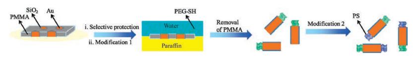
Herein, we report an effective method to fabricate Janus composite nanorods with controllable structure, as illustrated in Scheme 1. Firstly, SiO2 nanotubes array is prepared by sol-gel reaction on the inner surface of pores in a porous anodic aluminum oxide (AAO) membrane [36]. The pores are about 200 nm in diameter. A cable-like Au@SiO2 composite nanofiber array is obtained by depositing Au in the SiO2 nanotubes by electrodeposition. The as-formed Au fibers are closely adhered to the inner surface of SiO2 nanotubes. Then the AAO membrane is removed, and the as-formed gaps are filled with polymethyl methacrylate (PMMA). Following, the array of cable-like Au@SiO2 composite nanofibers is in a good order to be immobilized in the PMMA matrix. Then the interstitial voids between the nanofibers are filled with PMMA and the array has been completely embedded. The arrays of cable-like Au@SiO2 composite nanorods embedded within PMMA are vertically skived at a given step length and the slices with a certain thickness are obtained. One side of the slices is modified with thiol-group terminated poly(ethylene glycol)methyl ether (PEG-SH) in water while the other side is embedded in paraffin. Upon removal of PMMA and paraffin, cablelike Au@SiO2 Janus composite nanorods with one end modified are obtained. After modifying the other end of the Janus nanorods with thiol-group terminated polystyrene (PS-SH), the cable-like Au@SiO2 Janus composite nanorods modified with PS and PEG are achieved.

|
Download:
|
| Scheme1. Illustrative synthesis of the cable-like Au@SiO2 Janus composite nanorods. | |
All the used materials are commercialized products. The porous anodized aluminum oxide (AAO) membrane (pore diameter of ~200 nm) was purchased from Whatman Inc. The membrane is thick ~60 mm. Thiol-group terminated poly(ethylene glycol) methyl ether (PEG-SH, Mn = 12 k) and thiol-group terminated polystyrene (PS-SH, Mn = 16 k) were purchased from Polymer Source. Tetraethoxysilane (TEOS), chloroauric acid and cobalt sulfate were purchased from J & K Chemical. Methyl methacrylate (MMA), 2, 2'-azobisisobutyroni-trile (AIBN), tetrahydrofuran (THF), sodium sulfite, ammonium citrate, ethylenediaminetetraacetic acid (EDTA), potassium chloride and potassium hydroxide were obtained from Beijing Chemical Factory. Paraffin (Tm = 52.0–54.0 ℃), ethanol, nitric acid (HNO3) and hydrochloric acid (HCl) were obtained from Sinopharm Chemical Reagent. All reagents were used without further treatment.
After 0.48 g of TEOS, 3.465 g of ethanol and 0.843 g of HNO3 (0.2 mol/L) were mixed at ambient temperature, the AAO membrane was immersed for 24 h. Afterwards, the membrane was rinsed with abundant ethanol and deionized water to remove residual sol from the membrane surface. The sol absorbed membrane was further treated at 150 ℃ in air for 1 h to allow the formation of silica nanotubes against the channel pore surface by the sol-gel process. Constant potential of the three electrodes method was used at an Autolab (PGSTAT12) to electro deposit Au core within the internal cavity of the silica nanotubes embedded in the AAO membrane. An Ag/AgCl electrode as the reference (Uep = 0.250 V versus a standard hydrogen electrode (SHE)) and a platinum mesh as the counter electrode were used. A thin layer of Pt was sputtered onto one surface of the composite membrane, which acted as the working electrode. The electrolyte (15 mL) is composed of 1.0 g of chloroauric acid, 1.05 g of sodium sulfite, 1.2 g of ammonium citrate, 0.01 g of cobalt sulfate, 0.9 g of EDTA and 0.1 g of potassium hydroxide. The voltage was kept at -1.2 V. After electro-deposition for 7 h, the membrane was rinsed with deionized water for 3 times. After the composite membrane was embedded with PMMA, the AAO skeleton was dissolved with aqueous HCl (2 mol/L). After rinsing with ethanol and distilled water, the PMMA supported Au@SiO2 porous membrane was again filled and embedded with PMMA. By ambient skiving at a given step, slices within an array of cable-like Au@SiO2 composite nanorods were obtained. After one thin composite membrane was spread at a planar interface of melt paraffin/water at 70 ℃, the paraffin became frozen after cooling down to room temperature. Another PEG-SH aqueous solution (0.2 mg/mL) was added for conjugation of PEG onto one exposed surface of the membrane at ambient temperature for 24 h in nitrogen. Afterwards, the membrane/paraffin was treated with THF to remove paraffin and PMMA. The cable-like Au@SiO2 Janus composite nanorods were released. The nanorods were dispersed in 5 mL of PS-SH solution in DMF (0.2 mg/mL) in nitrogen to conjugate PS onto another end of the nanorods. After reaction for 12 h, the nanorods were rinsed with DMF. After centrifugation, the cable-like Au@SiO2 Janus composite nanorods were obtained.
Morphological observation of the samples was performed with a Hitachi S-4800 scanning electron microscope (SEM, Japan) equipped with an energy dispersive X-ray (EDX) analyzer operating at an accelerating voltage of 15 kV, a transmission electron microscopy (JEOL 1011 at 100 kV, Japan) and a transmission electron microscopy (JEOL 2100F at 200 kV, Japan) with an EDX analyzer. The samples for SEM observation were prepared by vacuum sputtering with Pt after ambient drying. The samples for TEM observation were prepared by spreading very dilute dispersions in ethanol onto carbon-coated copper grids. FT-IR spectroscopy measurement was performed using a Bruker EQUINOX 55 spectrometer with KBr pressed pellets. Leica EM UC7 ultramicrotome was used for the skiving.
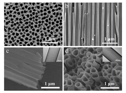
The channel of the used AAO membrane is about 200 nm in diameter, and regularly tubular structure (Figs. 1a and b). Sol-gel reaction of a silica precursor occurs against the channel surface to achieve the corresponding SiO2 nanotube. The preferential growth is attributed to the presence of large quantity of hydroxyl groups on the channel inner surface of AAO membrane. Diameter of the asformed SiO2 nanotube is similar with the channel diameter ~200 nm (Fig. 1c). Thickness of the SiO2 nanotube is tunable by varying the concentration of TEOS. As an example, thickness of the SiO2 nantube increases from 10 nm to 20 nm when TEOS concentration is increased from 0.03 g/mL to 0.1 g/mL (Fig. 1d).

|
Download:
|
| Fig. 1. SEM images of the AAO membrane: (a) top view, (b) side view; SEM and inset TEM images of two SiO2 nanotubes prepared at two different silica precursor concentration: (c) 0.03 g/mL, (d) 0.10 g/mL. | |
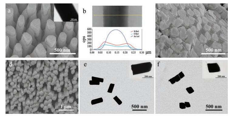
Inside the cavity of SiO2 nanotube, Au nanorod can be electrically deposited forming a kind of cable-like Au@SiO2 composite nanofiber. One side of the AAO membrane is previously coated with a layer of Pt ensuring a complete contact between the electrolyte and the electrode. The electro-deposition occurs from the Pt coated bottom surface [37]. Deposition rate is adjustable with the electro-deposition potential [38]. At a voltage of -1.2 V, the average electric current is 2.0 mA. A low deposition rate of 8.0 mm/h is achieved, which can guarantee no cavity between the Au nanorod and the SiO2 nanotube inner surface. Cable-like Au@SiO2 composite nanofibers are obtained after dissolution of AAO membrane (Fig. 2a). EDX analysis shows Au element is exclusively distributed in the core while a majority of O and Si elements are distributed within the shell (Fig. 2b). The cable-like of Au@SiO2 is thus confirmed.

|
Download:
|
| Fig. 2. (a) SEM image of the cable-like Au@SiO2 composite nanofibers after the AAO membrane is removed; (b) The corresponding EDX spectrum of a cable-like Au@SiO2 composite nanofiber; (c) SEM image of the section of the Au@SiO2-PMMA composite slice; (d) SEM image of the cable-like Au@SiO2 composite nanorod array after PMMA of Au@SiO2-PMMA composite slice (as shown in Fig. 2c) is removed; TEM images of the cable-like Au@SiO2 composite nanorods with different lengths (nm): (e) 400, (f) 200. | |
As the AAO membrane is too hard to skive, the Au@SiO2 composite nanofiber array is embedded with PMMA. After the Au@SiO2-AAO membrane is firstly embedded with PMMA via free radical polymerization, the AAO membrane is removed by wet etching with aqueous HCl. The Au@SiO2 composite nanofiber array is fixed with the outermost PMMA layer while one side is exposed. The gap between the Au@SiO2 composite nanofibers is filled with PMMA for a complete embedding. At a given skiving step length, the corresponding Au@SiO2-PMMA slices with tunable thickness are achieved (Fig. 2c). The Au@SiO2 composite nanorods are tightly embedded within the PMMA matrix without any gap. After a selective dissolution of PMMA, the cable-like Au@SiO2 composite nanorods are achieved (Fig. 2d). The nanorods are long ~400 nm, which is the same as the skiving step length. The nanorod is solid, and no cavity between Au and SiO2 is found under TEM (Fig. 2e). In fact, the nanorods length can be precisely tunable within the range of 30–15000 nm at the given skiving step length. As an example, a shorter Au@SiO2 composite nanorod about 200 nm in length is achieved while the diameter remains 200 nm (Fig. 2f).
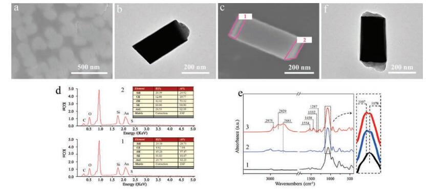
Janus Au@SiO2 composite nanorods are fabricated by favorable modification of the two end surfaces of the Au@SiO2 composite nanorods. The Au@SiO2-PMMA composite slice is firstly transferred at a water-liquid paraffin interface at 70 ℃. After cooling down to room temperature to solidify the interface, one side of the Au@SiO2-PMMA slice facing the paraffin phase is thus protected. The other surface is exposed to the aqueous phase. Upon adding PEG-SH in the aqueous phase, the corresponding end surface of the nanorod is selectively modified via conjugation of PEG-SH onto the Au surface (Fig. 3a). After paraffin and PMMA are dissolved with THF, PEG modified Janus Au@SiO2 composite nanorods are released (Fig. 3b). S element is present only onto one end of the nanorods, while the other end contains no S element (Figs. 3c and d). The presence of PEG is also verified by the FT-IR spectrum. The absorption peak at 2881cm-1 is attributed to the symmetrical stretching vibration of -CH2 and the absorptionpeak at 1107cm-1 is associated with the stretching vibration of C-O-C of PEG (Fig. 3e). This implies that the modification with PEG occurs onto one side the nanorods. The Other end surface of the PEG modified Janus Au@SiO2 composite nanorods can be conjugated with another polymer for example PS when using PS-SH. As a result, onto both end surfaces polymers can be found under TEM (Fig. 3f). The absorptionpeaks around 1554–1287cm-1 areattributedtothe skeleton vibration of benzene group. This reveals the presence of PS.

|
Download:
|
| Fig. 3. (a) SEM image of the PEG modified cable-like Au@SiO2-PMMAcomposite slice; (b) TEM image of PEG modified cable-like Au@SiO2 Janus composite nanorod; (c) SEM image of the PEG modified cable-like Au@SiO2 nanorod; (d) EDX spectrum of different region of the sample in Fig. 3c; (e) FT-IR spectra of the cable-like Au@SiO2 Janus composite nanorod (1, Au@SiO2 nanorod; 2, after conjugating PEG-SH onto one end; 3, after conjugating PEG-SH and PS-SH onto both ends, respectively); (f) TEM image of a cable-like Au@SiO2 Janus composite nanorod after conjugating PEG-SH and PS-SH onto both ends. | |
As a conclusion, we have proposed an easy method to fabricate cable-like Au@SiO2 Janus composite nanorods by skiving in combination of a post favorable modification. The cable-like Au@SiO2 composite nanofibers are synthesized in AAO membrane by a sol-gel process and electro-deposition. Length of the Janus composite nanorods is tunable. Two different polymers can be selectively conjugated onto the two end surfaces of the composite nanorods. The corresponding Janus nanorods are thus derived. This method can be extended to fabricate a variety of different Janus composite nanorods with tunable composition and microstructure.
AcknowledgmentThis work was supported by the National Natural Science Foundation of China (Nos. 51233007 and 51622308).
| [1] |
P.G. de Gennes, Rev. Mod. Phys. 64 (1992) 645-648. DOI:10.1103/RevModPhys.64.645 |
| [2] |
L. Hong, A. Cacciuto, E. Luijten, S. Granick, Nano Lett. 6 (2006) 2510-2514. DOI:10.1021/nl061857i |
| [3] |
A. Perro, S. Reculusa, S. Ravaine, E.B. Bourgeat-Lami, E. Duguet, J. Mater. Chem. 15 (2005) 3745-3760. DOI:10.1039/b505099e |
| [4] |
A. Walther, A.H.E. Müller, Chem. Rev. 113 (2013) 5194-5261. DOI:10.1021/cr300089t |
| [5] |
R. Erhardt, A. Boker, H. Zettl, et al., Macromolecules 34 (2001) 1069-1075. DOI:10.1021/ma000670p |
| [6] |
F.X. Liang, C.L. Zhang, Z.Z. Yang, Adv. Mater. 26 (2014) 6944-6949. DOI:10.1002/adma.v26.40 |
| [7] |
P. Zhou, B. Liu, F.X. Liang, et al., Chem. J. Chin. Univ. 36 (2015) 1431-1436. |
| [8] |
A. Walther, K. Matussek, A.H.E. Müller, ACS Nano 2 (2008) 1167-1178. DOI:10.1021/nn800108y |
| [9] |
H. Xu, R. Erhardt, V. Abetz, A.H.E. Müller, W.A. Goedel, Langmuir 17 (2001) 6787-6793. DOI:10.1021/la010091t |
| [10] |
S.H. Kim, A. Abbaspourrad, D.A. Weitz, J. Am. Chem. Soc. 133 (2011) 5516-5524. DOI:10.1021/ja200139w |
| [11] |
A. Walther, M. Hoffmann, A.H.E. Müller, Angew. Chem. Int. Edit. 47 (2008) 711-714. DOI:10.1002/(ISSN)1521-3773 |
| [12] |
C. Ma, H. Wu, Z.H. Huang, et al., Angew. Chem. Int. Edit. 54 (2015) 15699-15704. DOI:10.1002/anie.201507237 |
| [13] |
Z.Y. Liu, R.H. Guo, G.X. Xu, Z.H. Huang, L.T. Yan, Nano Lett. 14 (2014) 6910-6916. DOI:10.1021/nl5029396 |
| [14] |
M. Paulus, P. Degen, T. Brenner, et al., Langmuir 26 (2010) 15945-15947. DOI:10.1021/la102882j |
| [15] |
Q.A. Xu, X.W. Kang, R.A. Bogomolni, S.W. Chen, Langmuir 26 (2010) 14923-14928. DOI:10.1021/la102540n |
| [16] |
J.P. Ge, Y.X. Hu, T.R. Zhang, Y.D. Yin, J. Am. Chem. Soc. 129 (2007) 8974-8975. DOI:10.1021/ja0736461 |
| [17] |
K.P. Yuet, D.K. Hwang, R. Haghgooie, P.S. Doyle, Langmuir 26 (2010) 4281-4287. DOI:10.1021/la903348s |
| [18] |
J. Wang, K.M. Manesh, Small 6 (2010) 338-345. DOI:10.1002/smll.v6:3 |
| [19] |
W.F. Paxton, K.C. Kistler, C.C. Olmeda, et al., J. Am. Chem. Soc. 126 (2004) 13424-13431. DOI:10.1021/ja047697z |
| [20] |
L. Baraban, D. Makarov, R. Streubel, et al., ACS Nano 6 (2012) 3383-3389. DOI:10.1021/nn300413p |
| [21] |
M.E. Pearce, J.B. Melanko, A.K. Salem, Pharm. Res. 24 (2007) 2335-2352. DOI:10.1007/s11095-007-9380-7 |
| [22] |
D.M. Lv, W. Ni, F.X. Liang, et al., Chin. J. Polym. Sci. 33 (2015) 1344-1350. DOI:10.1007/s10118-015-1683-2 |
| [23] |
Y. Chen, Z. Liu, X.Z. Qu, F.X. Liang, Z.Z. Yang, J. Chem. Asian 11 (2016) 1785-1788. DOI:10.1002/asia.v11.12 |
| [24] |
S.Q. Cui, X.Y. Ji, F.X. Liang, Z.Z. Yang, Chin. Chem. Lett. 26 (2015) 942-945. DOI:10.1016/j.cclet.2015.04.034 |
| [25] |
J. Sun, W.G. Cheng, W. Fan, et al., Catal. Today 148 (2009) 361-367. DOI:10.1016/j.cattod.2009.07.070 |
| [26] |
Y.W. Chen, E.T. Kang, K.G. Neoh, A. Greiner, Adv. Funct. Mater. 15 (2005) 113-117. DOI:10.1002/(ISSN)1616-3028 |
| [27] |
B.A. Evans, A.R. Shields, R.L. Carroll, et al., Nano Lett. 7 (2007) 1428-1434. DOI:10.1021/nl070190c |
| [28] |
L.F. Boesel, C. Greiner, E. Arzt, A. del Campo, Adv. Mater. 22 (2010) 2125-2137. DOI:10.1002/adma.v22:19 |
| [29] |
A. Blanazs, M. Massignani, G. Battaglia, S.P. Armes, A.J. Ryan, Adv. Funct. Mater. 19 (2009) 2906-2914. DOI:10.1002/adfm.v19:18 |
| [30] |
L. Ionov, G. Stoychev, D. Jehnichen, J.U. Sommer, ACS Appl. Mater. Interfaces 9 (2017) 4873-4881. DOI:10.1021/acsami.6b13084 |
| [31] |
D. Dendukuri, D.C. Pregibon, J. Collins, T.A. Hatton, P.S. Doyle, Nature Mater. 5 (2006) 365-369. DOI:10.1038/nmat1617 |
| [32] |
Y.F. Liu, V. Abetz, A.H.E. Müller, Macromolecules 36 (2003) 7894-7898. DOI:10.1021/ma0345551 |
| [33] |
Q.B. Xu, R. Perez-Castillejos, Z.F. Li, G.M. Whitesides, Nano Lett. 6 (2006) 2163-2165. DOI:10.1021/nl0615672 |
| [34] |
Q.B. Xu, R.M. Rioux, M.D. Dickey, G.M. Whitesides, Acc. Chem. Res. 41 (2008) 1566-1577. DOI:10.1021/ar700194y |
| [35] |
Q. Zhou, J. Li, C.L. Zhang, et al., Polymer 51 (2010) 3606-3611. DOI:10.1016/j.polymer.2010.06.001 |
| [36] |
Z.L. Yang, J.L. Li, C.L. Zhang, Y.F. Lu, Z.Z. Yang, Chin. Chem. Lett. 24 (2013) 89-92. DOI:10.1016/j.cclet.2013.01.008 |
| [37] |
C.A. Foss, G.L. Hornyak, J.A. Stockert, C.R. Martin, J. Phys. Chem. 98 (1994) 2963-2971. DOI:10.1021/j100062a037 |
| [38] |
P. Forrer, F. Schlottig, H. Siegenthaler, M. Textor, J. Appl. Electrochem. 30 (2000) 533-541. DOI:10.1023/A:1003941129560 |