 2018, Vol. 29

 ,
Zhong'an Lia
,
Zhong'an Liab State Key Laboratory and Institute of Elemento-Organic Chemistry, College of Chemistry, Nankai University, Tianjin 300071, China
Nowadays, a great deal of worldwide attention is being paid to finding and developing new renewable energy sources due to the ever-increasing world energy need and the limited fossil fuel reserves.As sunlight is the most abundant, inexhaustible and clean energy, continuous efforts have been devoted on advancing new photovoltaic(PV) technologies that can convert sunlight into electricity efficiently.Today, crystalline silicon-based solar cells have been successfully reached mass production in the world. However, considering the limitation of silicon source and its high production cost, the need of more efficient and cheap PV materials becomes more and more critical.Within recent years, metal halide perovskites have proven to one of the best alternative PV materials owing to their excellent photovoltaic performance and low-cost production potential [1-4].So far, the maximum of power conversion efficiency(PCE) for perovskite solar cells(PVSCs) has rapidly improved from 3.8% to 23% in the past 8 years; such dramatically rapid improvement actually has never been seen in any other PV technologies by checking the chart of "Best ResearchCell Efficiencies" provided by National Renewable Energy Laboratory [5].
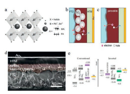
In the PVSCs, the structure of perovskite materials is typically denoted as ABX3 as shown in Fig. 1a [6], where A generally represents organic cations such as methylammonium(MA) CH3NH3+ and formamidinium(FA) HC(NH2)2+, while B is always the divalent metal cations like Pb2+ and Sn2+ and X for halide anions(I-, Br- and Cl-).Perovskite materials have several advantages over other inorganic/organic PV materials, including the intense absorption in a wide window up to 800 nm, high ambipolar charge transporting ability, long carrier diffusion length (>175 mm), and low exciton binding energy(< 25 meV) [7-12]. Besides, another attractive advantage of perovskites is their optoelectronic properties can be easily tuned by modifying organic cations and halide anions [13, 14].To date, two main device architectures(i.e., mesoscopic nanostructure and planar structure, Figs. 1b and c, respectively) have been developed to fabricate efficient PVSCs [15].A cross sectional SEM image of a mesoscopic nanostructure device is shown in Fig. 1d [16], based on which we can easily see the perovskite materials are filled into mesoporous scaffold made by n-type TiO2 or Al2O3 in other cases, while a very thin compact TiO2 layer is used as the electron transporting layer (ETL) on the bottom of scaffold, with a hole transporting layer (HTL) fabricated on the top.In this structure, electrons are collected directly and/or via compacted TiO2 layer.Unlikely, the mesoporous TiO2 scaffold can be totally removed when fabricating the planar structure devices attributed to the ambipolar nature of perovskites with long charge carrier diffusion length, in which the active perovskite layer is sandwiched by HTL and ETL.The planar structure can be further classified into n-i-p(conventional) and pi-n(inverted) configurations(Fig. 1e) [17].As shown, holes are extracted to bottom electrode for conventional device, while for inverted device electrons are extracted to bottom electrolyte. Compared to conventional device, the fabrication of most inverted devices do not need high temperature process, offering possibilities of achieving flexible devices through using polymer substrates [18].

|
Download:
|
| Fig. 1. a) Perovskite crystal structure.Copied with permission [6].Copyright 2016, Wiley Publishing Group.b) Mesoscopic structure PVSCs containing mesoporous TiO2 layer.c) Planar structure PVSCs without mesoporous TiO2 layer.Copied with permission [15].Copyright 2015, Wiley Publishing Group.d) Cross sectional SEM of a typical mesoscopic device.Copied with permission [16].Copyright 2015, Royal Society of Chemistry.e) Schematic illustration of conventional and inverted planar energy level alignment.Reproduced with permission [17].Copyright 2015, Wiley Publishing Group. | |
Perovskite materials were firstly used as the light absorber in solar cells by Miyasaka et al.in 2009, which however delivered a low PCE of 3.8% accompanying with a terrible device stability caused by the dissolution of perovskite into liquid electrolyte [19]. Sequentially, this stability problem was successfully solved by Snaith et al.though introducing an organic hole-transporting material(HTM) i.e., 2, 2', 7, 7'-tetrakis(N, N-di-p-methoxyphenylamine)-9, 9'-spirobifluorene(spiro-OMeTAD, 1 in Fig. 2) to replace the liquid electrolyte, and the PCE of resulting MAPbI3-xClx based PVSCs could be significantly improved to 10.9% with a much enhanced device stability [20].These very exciting results therefore triggered a worldwide research focus on PVSCs, and a significantly rapid progress has been made in the past 8 years.In addition to the optimization of the perovskite deposition approaches [21, 22], the selection of suitable charge carrier transporting layers also plays an important role in improving the device performance of PVSCs because they can effectively improve the Ohmic contact of interface between the absorber layer and electrode, and thus promote the charge collection efficiency [6, 9, 23-25].Moreover, the charge transport layer on the top of perovskites also can act as an effective protecting layer to enhance the device stability [26, 27].Therefore, an ideal HTM for efficient PVSCs should exhibit high carrier mobility, compatible energy levels with perovskites, low cost for easy scale-up, as well as longterm morphological stability.

|
Download:
|
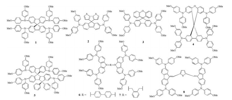
| Fig. 2. Chemical structures of doped HTMs 1–8 with spiro-type structure. | |
So far, most HTMs used in PVSCs involve a chemical doping process to ensure sufficient conductivity and shift the Fermi level towards the HOMO level for efficient hole transport and collection. p-Type dopants such as Li-bis(trifluoromethanesulfonyl)imide(LiTFSI) and silver bis(trifluoromethanesulfonyl)imide(AgTFSI) are generally used.However, such doping process not only improves the overall cost of the PVSCs, but also accelerates the degradation of cell performance due to the sophisticated oxidation procedure and undesired ion migration and interactions [28, 29].As a result, developing dopant-free HTMs is very critical to the achievement of highly efficient and stable PVSCs.Several reviews on HTMs for PVSCs have been already published [6, 9, 23-25], however most of them are focused on chemically doped HTMs.There is a lack of overview that is only focused on dopant-free HTMs, of which the recent advance is very fast.Thus in this review, after briefly introducing some effective doped HTMs for comparison, we will focus on summarizing the latest progress on new molecular design of dopant-free HTMs including small molecules and polymers. Finally, a short conclusion and outlook is also presented.
2. Small molecule doped HTMs for perovskite solar cells 2.1. Doped HTMs with spiro-type structureTo date, the commonly used small molecule HTMs for PVSCs should be the spiro-OMeTAD(1) and its derivatives, and a PCE as high as ~21% has been realized already through the careful device optimization [30].In the molecular structure of spiro-OMeTAD, the electron-rich methoxy substituents(-OMe) on triphenylamine units play a role in tuning the HOMO level, while the spiro building block can lead to good solubility, processibility and high glass transition temperature that is important to achieve good optical quality films with long-term thermal stability.Nevertheless, the spiro structure could prevent the intermolecular interactions to induce a low crystallinity, resulting in a poor hole mobility (~4 ×10⁻⁵cm2 V-1 s-1).Thus, p-type dopants need to be added to induce a doping effect that can effectively enhance the conductivity for hole transport and collection.Additionally, another disadvantage for spiro-OMeTAD is its relatively high synthetic cost(~500 USD/g).
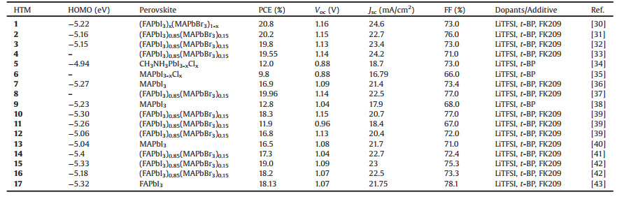
Much effort has been made to develop new alternative low-cost and efficient HTMs to replace the spiro-OMeTAD [6, 9, 23].The structure of selected high performance doped HTMs is shown in Fig. 2 with device parameters summarized in Table 1.Nazeeruddin et al.recently reported a simple and dissymmetric fluorenedithiophene(FDT) core based HTM 2 with a reduced synthetic cost of 60 USD/g, which can deliver a high PCE of 20.2% through using (FAPbI3)0.85(MAPbBr3)0.15 as the active perovskite layer [31]. Moreover, Sun et al.designed and synthesized another two lowcost HTMs 3 and 4 using the simple spiro-[fluorene-9, 9'-xanthene] (SFX) as the core, which only required two facile synthetic steps based on cheap commercially available materials [32, 33].The hole mobilities of 3 and 4 were measured to be 5.5 ×10⁻⁵ and 1.9 × 10⁻⁴cm2V-1s-1, respectively, and both PVSCs can achieve high PCEs close to ~20%.Guo and Nakamura et al.adopted the carbon-bridged oligophenylenevinylene as the conjugated backbone to design HTM 5, which can form a stable radical cation due to the 3-D homoconjugation [34].This unique structural feature not only can promote the resulting HTMs to easily form an amorphous and stable film, but also endow them with high hole mobilities that can enable comparable device performance to that of spiroOMeTAD.Sun et al.also prepared a new HTM 6 using(4, 4'-N, N'-dicarbazole)biphenyl(CBP) to replace spirofluorene as the core unit, however which only gave a low PCE of 9.8% [35]. Subsequently, HTM 7 with a similar structure to 6 was reported by Nazeeruddin et al.based on a simple two-step reaction using quite low-cost staring materials.The champion device from HTM 7 can reach a satisfied PCE of 16.91% [36].Recently, they also reported a facile synthesis of HTM 8 containing two methoxydiphenylamine-substituted fluorene fragments linked by a thiophene bridge [37].The synthetic cost of HTM 8 was estimated to only ~23 USD/g, while the PCE as high as 19.96% was achieved, making it one of good material candidates that is useful for large scale production.
|
|
Table 1 Photovoltaic properties of perovskite solar cells using doped HTMs 1–17 with spiro-type and star-shaped structure, and all the device architectures are mesoscopic. |
2.2. Doped HTMs with star-shaped structure
Forming a stable amorphous film is important to achieve high efficient and stable PVSCs, however for most small molecule HTMs, it remains as a challenge.Fortunately, the three-dimensional(3D) star-shaped structure has been well demonstrated to form ideal amorphous films, inspiring us to develop new HTMs with branched structure.A new star-shaped material(9) based on quinolizino acridine core was synthesized by Nazeeruddin et al.in 2014, which showed enhanced intermolecular π-π packing interactions and effective charge-transfer between the donor-acceptor group [38] (Fig. 3).HTM 9 showed a high hole mobility and thus a high PCE of 12.8% at that time.Then in 2015, they also prepared a new series of center symmetrical star-shaped HTMs 10–12 using triazatruxene as the core [39] and all these molecules exhibited good thermal stabilities and HTM 10 with three simple methoxyphenyl substituents particularly achieved a highest PCE of 17.7%.

|
Download:
|
| Fig. 3. Chemical structures of doped HTMs 9–17 with star-shaped structure. | |
Murata et al.prepared a new class of sheet-shaped HTMs such as 13 by introducing azulene ring as the central core to link four oxygen-bridged triarylamines [40], given azulene is a nonbenzenoid aromatic ring exhibiting both electron-donating and accepting character derived from five-and seven-membered ring, respectively.They demonstrated that a horizontal, face-on molecular orientation was found for the film of HTM 13, which can facilitate the charge collection to offer a superior PCE of 16.5% than that of referenced spiro-OMeTAD device.Moreover, Martín and Nazeeruddin et al.prepared three star-shaped HTMs 14–16 based on the benzotrithiophene(BTT) core, and carefully studied the isomerism effect of BTT core on their optical, electrochemical and photophysical properties [41, 42].HTM 15 in particular showed the highest conductivity of 5.3 × 10⁻⁴ S/cm, about 20 times higher than 14, and therefore afforded a highest PCE of 19%.Anthra [1, 2b:4, 3-b':5, 6-b'':8, 7-b''']tetrathiophene(ATT) unit is one of well-known building blocks to provide high hole mobility due to their strong π-π interactions.Nazeeruddin et al.recently prepared a new ATT-based HTM 17 with a small hole reorganization energy(0.096 eV) and a remarkable conductivity(5.8 × 10⁻⁴ S/cm), and a high PCE of 18.13% was obtained based on the FAPbI3 based PVSCs [43].
3. Small molecule dopant–free HTMsIn general, chemical doping process by adding p-dopant of LiTFSI with additive of 4-tert-butylpyridine(TBP) is widely used to improve the conductivity of HTMs.As introduced previously, this doping process has found to cause several stability problems.First, the oxidation process may induce a decomposition of perovskites and thus cause the decrease of device performance due to the introduction of oxygen [28].Moreover, both Li-TFSI and TBP have been found to interact with perovskite materials, and TBP even can dissolve perovskites to induce a corrosion phenomenon [44]. Besides, TBP can be evaporated at 85 ℃, therefore limiting the long-term device stability [45].In this context, developing dopantfree HTMs should be an effective solution to solve the above problems, and recently a particular research focus has been shifted on this field.Thus in this section, we will summarize the latest, encouraging progress on new molecular design of dopant-free HTMs that can enable efficient and stable PVSCs.
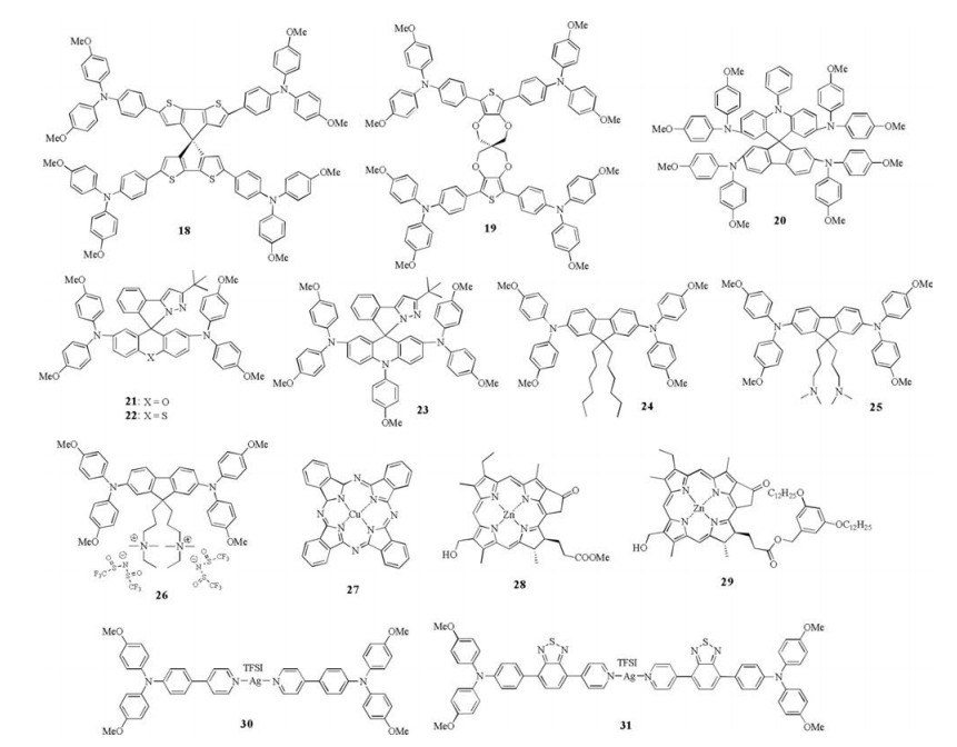
3.1. Dopant–free HTMs with spiro-type structureThe spiro concept is also used to prepare dopant-free HTMs such as 18-23, and their structures are summarized in Fig. 4 with device parameters listed in Table 2.Based on 4, 4'-spirobi[cyclopenta[2, 1-b:3, 4-b']dithiophene] core, Nakeeruddin et al.developed a new spiro-type HTM 18 [46].The hole mobility of HTM 18 was found to ~6.0 × 10⁻⁶cm2V-1s-1, but can be improved to 3.0 ×10⁻⁵cm2V-1s-1 when treated under light for several minutes.Therefore, a considerable PCE of 13.4% can be achieved for HTM 18 without any dopants.Moreover, another spiro-type molecule 19 was also prepared with low synthetic cost [47].Two thiophene units and four connecting oxygen atoms in the core of 19 were close to coplanar, and four triphenylamine units showed the same direction of distortion, making the structure of 19 more planar than that of spiro-OMeTAD.A higher hole mobility for 19 was achieved due to the enhanced molecular packing, making it serve as dopant-free HTM and result in a PCE of 12.74% based on MAPbI3-based PVSCs.Jiang and Liao et al.synthesized a new HTM 20 by incorporating the N-benzene-N structure into the spirostructure [48].The fabricated PVSCs based on HTM 20 with and without doping process can produce a PCE of 16.73% and 12.39%, respectively.

|
Download:
|
| Fig. 4. Chemical structures of dopant-free HTMs 18–31 with spiro-type and organometallic structure. | |
|
|
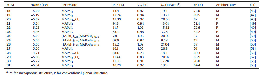
Table 2 Photovoltaic properties of perovskite solar cells using dopant-free small HTMs 18–31 with spiro-type and organometallic structure. |
Recently, Chi and Jen et al.introduced O, S or N atom into the pyrazole-based sipro structure to prepare three new spiro-type HTMs 21–23 [49].Due to the improved molecule packing and charge transport character, HTMs 21 and 22 showed enhanced hole mobilities of 7.03 ×10⁻⁵ and 9.14 ×10⁻⁵cm2V-1s-1, respectively, much higher than HTM 23.Therefore without adding dopant, PVSCs based on HTM 21 and 22 achieved PCEs of 9.13% and 11.7%, respectively.However for HTM 23, the introduction of methoxyphenyl group in core can hamper the intermolecular stacking and increase the HOMO level to be -4.96 eV; these unfavorable factors resulted in a quite low PCE of 5.01%.Recently, Johansson et al.investigated the impact of counter ions in the side chains on the device performance by designing three HTMs 24–26, wherein fluorene ring was used as the π-bridge to connect two diphenylamine groups [50].It was interestingly found the hole mobility of 26 can be significantly enhanced due to the ionization of sidechains and achieved as high as 9.03 ×10⁻⁴cm2V-1s-1, one order of magnitude higher than 24(7.65 ×10⁻⁵cm2V-1s-1) and 25 (8.95 ×10⁻⁵cm2V-1s-1), indicating the counter ions play a similar role like dopants; maybe a self-doping effect.As a result, a large difference on device performance was demonstrated when using them as the dopant-free HTMs, and the PCE was changed from 0.08% for 24 to 7.8% for 25, and to 15.2% for 26, suggesting a new design-strategy towards dopant-free HTMs.
3.2. Organometallic dopant–free HTMsThe organmetallic HTMs generally possess high hole transport ability due to the strong and ordered molecular packing.Moreover, the abundant source and low cost of synthesis make them very easy to scale up.However few examples can be applied on PVSCs owing to a lack of effective approach of tuning their energy levels. So far, only several organmetallic HTMs were reported in PVSCs as shown in Fig. 4, and the device parameters are listed in Table 2. Yang et al.firstly introduced nanorod-liked copper phthalocyanine (CuPc, 27) as the dopant-free HTM, and through using low temperature printable carbon as the cathode, a high PCE of 16.1% can be obtained [51].In addition to high hole mobility up to 10-2cm2V-1s-1, the nanorod-liked CuPc also showed a large interfacial-area contact with both perovskite layer and electrode, and thus resulted in a significantly improved hole-extraction efficiency and stability.It should be noted that the PCE only decreased from 16.1% to 14.1% after 600 h.
Wang et al.employed chlorophylls as the building blocks to prepare dopant-free HTMs 28 and 29 [52].The hole mobilities of 28 and 29 were determined to 1.55 ×10⁻³ and 6.49 × 10⁻³ cm2V-1s-1, respectively, attributed to their self-assembly into Jaggregates via intermolecular interactions.Dopant-free PVSCs based on HTM 29 delivered a higher PCE of 11.44%, while that of HTM 28 was only 8.06% mainly due to the relative high HOMO level of -4.71 eV.Recently, Sun et al.developed two Ag-based organic metal complexes(30 and 31) as the dopant-free HTMs [53].The synthesis of these two compounds is very simple with high yields without involving any column chromatography. Compared with HTM 30(6.49 ×10⁻⁴cm2V-1s-1), HTM 31 showed a slight higher hole mobility of 8.38 × 10⁻⁴cm2V-1s-1 due to the enhanced π-π stacking induced by the introduction of benzothiadiazole unit.Nonetheless, the dopant-free PVSCs based on HTM 30 afforded a PCE of 11.98% under ambient atmosphere conditions, even slightly higher than that of 31 based device (10.79%), attributed to the more suitable HOMO energy level of former.
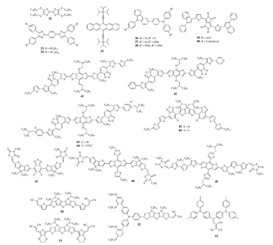
3.3. Dopant-free HTMs with linear structureDopant-free HTMs with linear structure are summarized in Fig. 5, and their device parameters are given in Table 3.In fact, TTF-1(32) was the first dopant-free HTM used in PVSC reported by Han et al.in 2014 due to its hole mobility as high as 0.1cm2V-1s-1 [54]. Dopant-free device based on 32 can show a PCE of 11.03%, which is a relatively good value at that time.It is worth noting that the PCE of 32-based PVSCs unusually decreased from 11.03% to 4.41% after chemical doping.Lin et al.synthesized two new HTMs 33 and 34 with heterocyclic quinoid-based structure and different alkoxy chains were introduced [55].These two materials exhibited the same HOMO and LUMO levels, but the hole mobility of 34 was much higher than that of 33.As a result, the PCEs of resulting dopant-free devices based on HTM 33 and 34 were 7.79% and 12.22%, respectively.Moreover, taking advantage of high hole mobility of pentacene, Ahmad et al.employed 6, 13-bis(triisopropylsilylethynyl) pentacene(35) as the dopant-free HTM to fabricate PVSCs with a moderate PCE of 11.8% [56].Park et al. design a series of triarylamine-carbazole derivatives(36-38) by introducing different number of methoxy groups [57].They revealed that the methoxy groups played an important role in increasing the efficiency of charge extraction as well as reducing the charge recombination, and thus dopant-free PVSCs based on 38 with three methoxy substituents showed a best PCE of 16.58%.

|
Download:
|
| Fig. 5. Chemical structures of dopant-free HTMs 32–53 with linear and D-A structure. | |
|
|
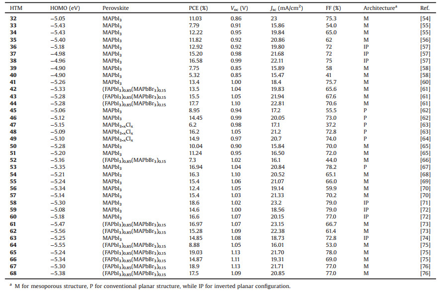
Table 3 Photovoltaic properties of perovskite solar cells using dopant-free small HTMs 32–68 with linear, D-A and star-shaped structure. |
3.4. Dopant-free HTMs with linear D-A structure
So far, one effective molecular design strategy towards dopantfree organic HTMs is to use electron donor(D)-acceptor(A) scaffolds, and through rationally combining different donor groups and acceptor groups, a series of dopant-free HTMs have been developed as shown in Fig. 5 with device parameters listed in Table 3.D-A structure generally exhibits a strong dipole-dipole interactions to enhance the molecular packing and thus to improve hole transport ability.Using N-phenyl-indole as the donor while diketopyrrolopyrrole(DPP) as the acceptor, Kim et al.prepared two new D-A type dopant-free HTMs(39 and 40) with PCEs of 7.75% and 5.32%, respectively [58].Electron-donating benzodithiophene (BDT) unit has been widely used in organic photovoltaics for designing state-of-art p-type polymer donors [59].Using BDT as the donor and benzo-[c][1, 2, 5]-thiadiazole(BT) as the acceptor, Sun et al.developed a new A-D-A type dopant-free HTM 41 with a suitable energy level of -5.26 eV and good hole mobility of 3.18 × 10⁻⁴cm2V-1s-1, enabling the fabricated inverted PVSCs with a PCE of 13.4% [60].They further prepared three BDT based HTMs 42-44 end-capped with pyridine groups [61].With the ionization of end-capping pyridine units, the resulting HTMs 43 and 44 showed much higher hole mobilities up to ~3 ×10⁻⁴ cm2 V-1 s-1 than the neutral 42, and thus much higher conductivities over 1 ×10⁻⁴ S/cm.Thus, the fabricated PVSCs based on dopant-free HTM 44 can produce an encouraging PCE OF 17.7%. Furthermore, Hae et al.prepared two new A-D-A dopant-free HTMs 45 and 46 using dithienosilole(DTS) as the donor while BT as the acceptor, resulting in PCEs of 8.95% and 14.45%, respectively [62].Further with DTS as the donor however 3-alkyl rodanine as the acceptor, Yang et al.designed two A-D-A type HTMs 47 and 48, in which two different cores were introduced [63].It was found the core of 5, 6-difluoro-2, 1, 3-benzothiadiazole(DFBT) resulted in a incompatible HOMO energy level(-5.5 eV) of 47, which therefore only delivered a low PCE of 6.2%.On the contrary, HTM 48 with BDT core possessed a more suitable energy level and a much higher hole mobility compared to HTM 47, enabling a much enhanced PCE of 16.2%.Furthermore, they also reported the use of 49 as dopantfree HTM to give a PCE of 14.9% by replacing two DTS units in 48 with terthiophene groups [64].
Using S, N-heteropentacene unit as the donor, Mishra et al. designed and prepared two new A-D-A type HTMs(50 and 51) consisting of two dicyanovinylene acceptors, which, as dopant-free HTMs, achieved PCEs of 11.4% and 10.3%, respectively [65].Another S, N-heteropentacene-based HTM 52 was reported by Hagfeldt et al.[66], wherein S, N-heteropentacene serves as the π-spacer to link triarylamine donor with dicyanovinylene acceptor.The HTM 52 based PVSCs can show a good PCE of 16.9% with Li-TFSI/TBP doping, while without doping process, a decreased PCE of 7.3% was obtained.Recently, Li and Jen et al.demonstrated a rational design of donor-acceptor(D-A) substituted dipolar chromophore 53, which was synthesized via a simple reaction between triphenylamine-based Michler's Base(as donor) and tricyanovinylene(as acceptor).HTM 53 can serve as an efficient dopant-free HTM for PVSCs with a high PCE of ~17.0%, outperforming the control device using doped spiro-OMeTAD as HTM [67].They showed HTM 53 not only interestingly exhibited a zwitterionic resonance structure in the ground state, but also formed an antiparallel molecular packing (i.e., centrosymmetric dimers) in the solid state, both of which are favorable for coherent charge delocalization to facilitate hole transport.
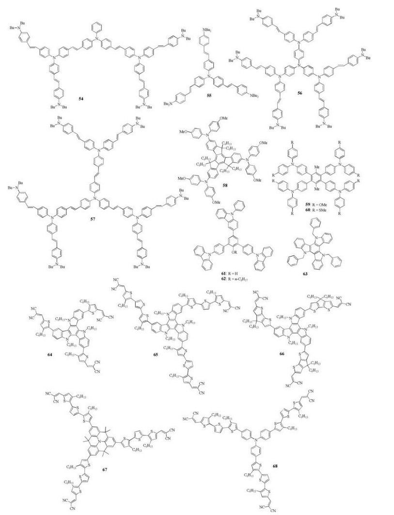
3.5. Dopant-free HTMs with star-shaped structureRational design of star-shaped structure provides another possible strategy to prepare dopant-free HTMs, as it can induce better π-π interactions to improve hole transport.The structure of star-shaped dopant-free HTMs 54–66 is shown in Fig. 6, while their device parameters are listed in Table 3.As shown, Wang, Zakeeruddin and Grätzel el al.designed and synthesized a series of triphenylamine-based dopant-free HTMs 54–57 [68-70].HTM 54 seems like a butterfly-shaped structure while others are starshaped structure having different generations.It was found that due to high hole mobility of 8.24 ×10⁻⁴cm2V-1s-1 and suitable HOMO level, the fabricated MAPbI3-based PVSCs of HTM 54 achieved a highest PCE of 16.3% with enhanced device stability [68], while HTM 56 showed a lowest PCE of 12.4% owing to its low hole mobility of 9.74 ×10⁻⁵cm2V-1s-1 [70].For HTM 55 and 57, the same PCE of 15.4% was obtained [69, 70], indicating there is no clear relationship between the size of dendrimer and device performance.Moreover, it should be noted the synthesis of HTM 55 is quite easy via a one-step Heck reaction from cheap commercial materials [69].

|
Download:
|
| Fig. 6. Chemical structures of dopant-free HTMs 54–68 with star-shaped structure. | |
Li, Jen and Chen et al.designed and synthesized a planar and fully conjugated HTM, Trux-OMeTAD(58) using truxene as the core [71].The planar truxene core enabled a face-on packing resulting in an excellent hole mobility of 2.3 ×10⁻³cm2V-1s-1, about two order of magnitude higher than spiro-OMeTAD.Six aliphatic chains in the core can improve the hydrophobility of molecule to induce a large contact angle of 90.4°, which therefore can protect the underlying perovskite film from moisture.Due to the high hole mobility, 58 can serve as dopant-free HTM, and the resulting inverted PVSCs showed an impressive PCE of 18.6%.More recently, they further synthesized two new tetraphenyl-based dopant-free HTMs 59 and 60 containing different type of substituents on the triphenylamine units [72].They demonstrated that the HOMO level can be effectively lowered by replacing methoxy group with methylthio group, which also resulted in a surface traps passivation effect.As a result, without any doping process, methylthio group functionalized HTM 60 endowed the fabricated PVSCs with a much enhanced PCE of 16.6% with reduced hysteresis, compared to that of HTM 59(14.6%).
Li et al.developed two star-shaped HTMs 61 and 62 using phenol group as the core to link three carbazole groups with different side-chains [73].Though both two HTMs showed low hole mobilities of 4.0 × 10⁻⁶cm2V-1s-1, the resulting dopant-free devices based on 61 and 62 achieved a high PCE of 16.97% and 15.28%, respectively, attributed to an obvious electron blocking effect induced by their high LUMO levels.Shahzada et al.used the triazatruxene as the core to prepare a new HTM 63, and efficient dopant-free devices can be fabricated to show a PEC of ~15% with negligible hysteresis in combination with a thin MoO3 film(5 nm) [74].Very recently, by integrating two design concepts of D-A and star-shaped structure, Nazeeruddin et al.prepared three new triazatruxene-based dopant-free HTMs 64–66 wherein π-bridges between the triazatruxene donor and dicyanovinylene acceptor were modified carefully with 3-hexylthiophene, 3, 3''-dihexyl-2, 2':5', 2''-terthiophene and 4, 4-dihexyl-4H-cyclopenta[2, 1-b:3, 4-b']dithiophene, respectively [75].A highly ordered face-on formed columnar stack was demonstrated for HTM 65, resulting in enhanced vertical hole transport and thus an impressively high PCE over 19% with improved device stability.Dopant-free device based on HTM 66 gave a PCE of 14.87% while that of HTM 65 was only 8.88%.These results thus indicate the importance of π-bridges on the HOMO level and hole mobility of resulting D-A type HTMs, which need to be taken in account when designing new HTMs. Furthermore, they recently reported another two new D-A type dopant-free HTMs 67 and 68 based on quinolizino acridine and triphenylamine core, respectively [76], and both dopant-free devices achieved high PCEs(18.9% for 67, while 17.5% for 68), due to their suitable HOMO levels and high hole mobilities.In addition, it was impressively found that the PCE of 67-based devices remained 65% of its original value after 1300 h, suggesting good device stability.
4. Polymer HTMsMany p-type conjugated polymers widely used in OPVs have been also used as HTMs in the PVSCs, as they often have good hole mobility and compatible energy levels.More importantly, polymer HTMs generally exhibit very good processibility to ensure high optical quality films with long-term morphological stability, which is expected to protect the instable perovskites.The structures of polymer HTMs 69–97 are shown in Fig. 7, while their device parameters are listed in Table 4.

|
Download:
|
| Fig. 7. Chemical structures of conjugated side-chain and D-A type polymer HTMs 69–97. | |
|
|
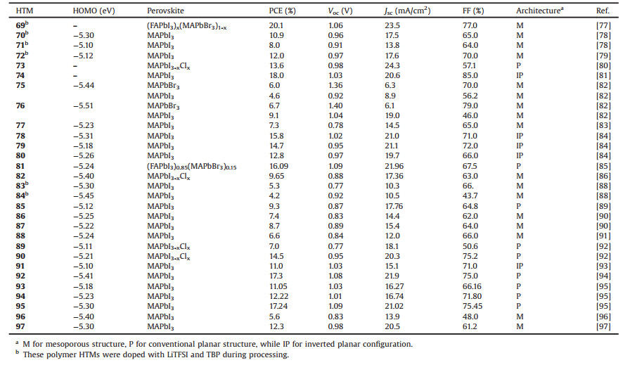
Table 4 Photovoltaic properties of perovskite solar cells using polymer-based HTMs 69–97. |
4.1. Conjugated side–chain polymer HTMs
Many classical conjugated side-chain polymers, particularly based on triphenylamine units, were tested as the HTMs in PVSCs due to their high hole mobilities.As a typical example, PTAA(69) was the first polymer employed as HTM in PVSCs by Seok et al., and has become a star HTM in this field as it can provide a very promising PCE of ~20% through careful device optimization [77]. On basis of PTAA structure, polymer HTMs 70–72 were also designed and employed as the doped HTMs in mesoscopic PVSCs, however achieved limited device performance [78, 79].
The well-known P3HT(73) was also used as HTM, based on which efficient dopant-free PSVSs using ultrathin TiO2 film(5– 20 nm) as EFL was fabricated to deliver a PCE of 13.6% [80].Moreover, a high PCE of 18.0% with enhanced stability can be achieved when using PEDOT:PSS(74) as the dopant-free HTM for inverted PVSCs [81].Seok et al.synthesized two polytriarylamine derivatives(75 and 76) as the dopant-free HTMs, both of which can achieve a high open circuit voltage close to ~1.4 V and thus enabled a satisfied PCE over 6.0% if considering MAPbBr3 as light absorber in PVSCs [82].Based on a two-step cyclic voltammetry approach directly onto the fluorinated tin oxide glass substrate(FTO), dual function of polyaniline(PANI, 77) was prepared as HTM for PVSCs, resulting in a PCE of 7.3% that can still keep 91.42% after 1000 h [83].On the other hand, three polymers HTMs 78–80 were synthesized by Yan et al.via the electrochemical polymerization method, and the best PCE of 15.8% was obtained for 78-based dopant-free PVSCs [84].Recently, Huang et al.developed a new non-conjugated polymer(81) with good solubility as dopant-free HTM in conventional PVSCs, and the fabricated(FAPbI3)x (MAPbBr3)1-x based PVSCs exhibited a high PCE of 16.09% [85]. Also, Ho et al.used MEH-PPV(82) as the dopant-free HTM in onestep method fabricated MAPbI3-based PVSCs, offering a PCE of 9.65% with hysteresis-less [86].
4.2. D–A type polymer HTMsD-A type copolymers recently have been found as effective HTMs for highly efficient and stable PVSCs.This design strategy can ensure both high hole mobility and compatible HOMO level useful for efficient hole extraction and transport through rationally integrating different donors and acceptors.Moreover the introduction of suitable conjugated side-chain groups into their backbones to form two-dimensional(2D) polymers can effectively tune their bandgaps, energy levels, charge carrier mobilities, as well as crystalline properties to fulfill the material requirements of high performance HTMs [59, 87].In 2013, Seok et al.first used two D-A copolymers PCPDTBT and PCDTBT(83 and 84) as the doped HTMs in PVSCs, resulting in a PCE of 5.6% and 9.2%, respectively [88].Later on, BDT-based copolymers were widely used as the dopant-free HTMs.Yang et al.introduced BDT-based polymer, PBDTTT-C(85), as the HTM in the ETL-free planar PVSCs [89], and due to its high mobility(2.4 ×10⁻⁴cm2V-1s-1) and suitable HOMO level(-5.12 eV), the desired dopant-free devices based on 85 achieved a moderate PCE of 9.95%.Subsequently, Park et al. reported another two 2D BDT-based polymers(86 and 87) as the dopant-free HTMs in PVSCs [90], and found introducing dichlorobenzene groups as side chains can promote hole transport and prevent charge recombination at the same time.As a result, the PVSCs based on 87 gave a higher PCE of 8.7% than that of 86(7.4%). Besides, Sharma et al.developed a new D-A copolymer 88 based on BDT donor and BT acceptor, endowing the dopant-free PVSCs with a PCE of 6.6% [91].
Using BDT donor and 2, 6-dialkylated-benzo[1, 2-d; 4, 5-d']bistriazole(BBTa) acceptor, Marks recently et al.prepared two new D-A type dopant-free polymer HTMs 89 and 90, both of which presented strong interchain interactions and substantial quinoidal π-character [92].A preferential π-face-on stacking morphology was found in the thin film of 90, leading to enhanced hole mobility and thus a higher PCE of 14.5% than that of 89(7.0%).More encouragingly, the device ambient stability was improved significantly for 90-based PVSCs after encapsulation, and the PCE can be maintained almost after 500 h., while that of doped spiro-OMeTAD-devices fall to about ~15% of its initial PCE under the same conditions.
Lee et al.fabricated the planar PVSCs with a PCE of 12.2% through using 2D BDT-based polymer 91 as the dopant-free HTM and PCBM modified ZnO nanoparticles as ETM [93].Park et al. designed and prepared a random 2D-BDT-based terpolymer 92 by integrating two types of polymers with complementary characters(one has high hole mobility but with too deep HOMO level, another one has a more suitable HOMO level but with a low mobility) [94].The random 92 thus showed a favorable HOMO level of -5.41 eV and a high hole mobility of 3.09 × 10⁻³ cm2 V-1 s-1, enabling the dopant-free device with a considerable high PCE of 17.3%.Moreover, a significant improvement on the long-term stability for 92-based devices was also realized which maintained its initial PCE after 1400 h.This should be due to the hydrophobic nature of 92 and the absence of deliquescent and hygroscopic dopants.Recently, Jin et al.studied the effect of fluorine atom by synthesizing three π-conjugated copolymers (93–95) with different number of fluorine atoms [95].The introduction of fluorine atom not only tunes the HOMO levels, but also improves the planarity of backbone to enhance the charge transport.Thus, polymer 95 with two fluorine atoms showed the highest hole mobility of 2.01 ×10⁻³cm2V-1s-1 among these three polymers, and as the dopant-free HTM for conventional PVSCs, it can produce a high PCE of 17.28% with good device stability.Besides, two DPP-based polymers(96 and 97) were also employed as the dopant-free HTMs, and gave PCEs of 5.6% and 12.3%, respectively [96, 97].
5. Conclusion and outlookWithin a short time, significant progress has been achieved for PVSCs due to the unique and very promising semiconducting properties for perovskite materials, and the maximum of PCE has reached the certified 23%, rivaling that of the crystalline silicon based photovoltaics.Organic HTMs can effectively improve the efficiency of hole transport and collection, and thus play an important role in improving the device performance of PVSCs. Many new HTMs have been developed and applied for PVSCs towards high efficiency.However, most of them require additional chemical doping process to ensure sufficient conductivity and shift the Fermi level towards the HOMO level.This doping process has been proven to not only increase the complexity and cost of device fabrication, but also deleteriously affect the device stability due to the sophisticated oxidation procedure and undesired ion migration and interactions, suggesting development of efficient dopant-free HTMs is urgently needed.In this review, we have given an overview of the latest advances in dopant-free HTMs including small molecules and polymers, and discussed the new molecular design strategies towards efficient and stable dopant-free HTMs.
So far, two major design strategies, D-A type and branched structure, have been chosen to prepare high performance dopantfree HTMs, due to they can enable better intermolecular interactions to increase the charge mobility/conductivity of resulting materials.In general, no doping process is required for efficient hole transport and collection if a HTM can exhibit a hole mobility as high as 10-4 ~ 10-3cm2V-1s-1, combining with suitable energy levels.The long term stability of PVSCs is one of critical issues that need to be addressed for their commercial applications.Removing the dopants only can mitigate the device stability problem to some degree.If considering the intrinsic instability of perovskites, we need the dopant-free HTMs that can form intact, pinhole-free film on the top of perovskite layer, and thus function as an efficient protecting layer of underlying perovskites from moisture, oxygen and UV light.As a result, in addition to low synthetic cost for large-scale production, high hole mobility and suitable energy levels, decent hydrophobicity and stable morphology is highly desirable for the rational design of new dopant-free HTMs.Dopant-free polymer HTMs recently have shown to achieve both high efficiency and device stability, however they suffer the drawbacks of batch-to-batch reproducibility, purity and high synthetic cost.Another promising approach is to make the film of small molecule HTMs crosslinked after deposited on the perovskite layer, and the major challenge is to search suitable crosslinking chemistry.Moreover, we have to better understand how the HTM interact with perovskite layer at the interface as well as the role of surface dipolar, since these factors are related to the minimization of recombination losses. Overall, it is believed that in the near future, further enhancement on the overall device performance of PVSCs can be achieved through the rational design of new dopant-free HTMs with comprehensive properties.
AcknowledgmentsThis work was supported by grants from the National Natural Science Foundation of China(Nos.21704030, 21602115).Z.Li and D.Zhao thank the financial support from the National 1000 Young Talents Program hosted by China.Z.Li also thanks the independent innovation research funding from HUST.
| [1] |
L. Etgar, P. Gao, Z. Xue, et al., J.Am.Chem.Soc. 134(2012) 17396-17399. DOI:10.1021/ja307789s |
| [2] |
M. Liu, M.B. Johnston, H.J. Snaith, Nature 501(2013) 395-398. DOI:10.1038/nature12509 |
| [3] |
P. Gao, M. Gratzel, M.K. Nazeeruddin, Energy Environ.Sci. 7(2014) 2448-2463. DOI:10.1039/C4EE00942H |
| [4] |
M.A. Green, A. Ho-Baillie, H.J. Snaith, Nat.Photonics 8(2014) 506-514. DOI:10.1038/nphoton.2014.134 |
| [5] | |
| [6] |
L. Calió, S. Kazim, M. Grätzel, S. Ahmad, Angew.Chem.Int.Ed. 55(2016) 14522-14545. DOI:10.1002/anie.201601757 |
| [7] |
S. Kazim, M.K. Nazeeruddin, M. Grätzel, S. Ahmad, Angew.Chem.Int.Ed. 126(2014) 2854-2867. DOI:10.1002/ange.v126.11 |
| [8] |
J. Burschka, N. Pellet, S.J. Moon, et al., Nature 499(2013) 316-319. DOI:10.1038/nature12340 |
| [9] |
W. Nie, H. Tsai, R. Asadpour, et al., Science 347(2015) 522-525. DOI:10.1126/science.aaa0472 |
| [10] |
H. Zhou, Q. Chen, G. Li, et al., Science 345(2014) 542-546. DOI:10.1126/science.1254050 |
| [11] |
T.J. Savenije, C.S. Ponseca, L. Kunneman, et al., J.Phys.Chem.Lett. 5(2014) 2189-2194. DOI:10.1021/jz500858a |
| [12] |
Q. Dong, Y. Fang, Y. Shao, et al., Science 347(2015) 967-970. DOI:10.1126/science.aaa5760 |
| [13] |
P. Qin, S. Tanaka, S. Ito, et al., Nat.Commun.5(2014), 3834. |
| [14] |
N. Pellet, P. Gao, G. Gregori, et al., Angew.Chem.Int.Ed. 126(2014) 3215-3221. DOI:10.1002/ange.201309361 |
| [15] |
H.S. Jung, N.G. Park, Small 11(2015) 10-25. DOI:10.1002/smll.201402767 |
| [16] |
A. Abate, S. Paek, F. Giordano, et al., Energy Environ.Sci. 8(2015) 2946-2953. DOI:10.1039/C5EE02014J |
| [17] |
S.F. Volker, S. Collavini, J.L. Delgado, ChemSusChem 8(2015) 3012-3028. DOI:10.1002/cssc.201500742 |
| [18] |
P. Docampo, J.M. Ball, M. Darwich, G.E. Eperon, H.J. Snaith, Nat.Commun 4(2013) 2761. |
| [19] |
A. Kojima, K. Teshima, Y. Shirai, T. Miyasaka, J.Am.Chem.Soc. 131(2009) 6050-6051. DOI:10.1021/ja809598r |
| [20] |
M.M. Lee, J. Teuscher, T. Miyasaka, T.N. Murakami, H.J. Snaith, Science 338(2012) 643-647. DOI:10.1126/science.1228604 |
| [21] |
A. Sharenko, M.F. Toney, J.Am.Chem.Soc. 138(2016) 463-470. DOI:10.1021/jacs.5b10723 |
| [22] |
J. Seo, J.H. Noh, S.I. Seok, Acc.Chem.Res. 49(2016) 562-572. DOI:10.1021/acs.accounts.5b00444 |
| [23] |
F. Ullah, H. Chen, C.Z. Li, Chin.Chem.Lett. 28(2017) 503-511. DOI:10.1016/j.cclet.2016.11.009 |
| [24] |
Y. Yu, P. Gao, Chin.Chem.Lett. 28(2017) 1144-1152. DOI:10.1016/j.cclet.2017.04.020 |
| [25] |
Z. Yu, L. Sun, Adv.Energy Mater 5(2015) 1500213. DOI:10.1002/aenm.201500213 |
| [26] |
Y. Li, Y. Zhao, Q. Chen, et al., J.Am.Chem.Soc. 137(2015) 15540-15547. DOI:10.1021/jacs.5b10614 |
| [27] |
Z.A. Li, Z. Zhu, C.C. Chueh, J. Luo, A.K.Y. Jen, Adv.Energy Mater 6(2016) 1601165. DOI:10.1002/aenm.201601165 |
| [28] |
Z. Hawash, L.K. Ono, S.R. Raga, M.V. Lee, Y. Qi, Chem.Mater. 27(2015) 562-569. DOI:10.1021/cm504022q |
| [29] |
X. Zhao, N.G. Park, Photonics 2(2015) 1139-1151. DOI:10.3390/photonics2041139 |
| [30] |
D. Bi, W. Tress, M.I. Dar, et al., Sci.Adv 2(2016) e1501170. DOI:10.1126/sciadv.1501170 |
| [31] |
M. Saliba, S. Orlandi, T. Matsui, et al., Nat.Energy 1(2016) 15017. DOI:10.1038/nenergy.2015.17 |
| [32] |
D. Bi, B. Xu, P. Gao, et al., Nano Energy 23(2016) 138-144. DOI:10.1016/j.nanoen.2016.03.020 |
| [33] |
B. Xu, D. Bi, Y. Hua, et al., Energy Environ.Sci. 9(2016) 873-877. DOI:10.1039/C6EE00056H |
| [34] |
Q. Yan, Y. Guo, A. Ichimura, H. Tsuji, E. Nakamura, J.Am.Chem.Soc. 138(2016) 10897-10904. DOI:10.1021/jacs.6b04002 |
| [35] |
B. Xu, E. Sheibani, P. Liu, et al., Adv.Mater. 26(2014) 6629-6634. DOI:10.1002/adma.v26.38 |
| [36] |
P. Gratia, A. Magomedov, T. Malinauskas, et al., Angew.Chem.Int.Ed. 54(2015) 11409-11413. DOI:10.1002/anie.201504666 |
| [37] |
T. Malinauskas, M. Saliba, T. Matsui, et al., Energy Environ.Sci. 9(2016) 1681-1686. DOI:10.1039/C5EE03911H |
| [38] |
P. Qin, S. Paek, M.I. Dar, et al., J.Am.Chem.Soc. 136(2014) 8516-8519. DOI:10.1021/ja503272q |
| [39] |
K. Rakstys, A. Abate, M.I. Dar, et al., J.Am.Chem.Soc. 137(2015) 16172-16178. DOI:10.1021/jacs.5b11076 |
| [40] |
H. Nishimura, N. Ishida, A. Shimazaki, et al., J.Am.Chem.Soc. 137(2015) 15656-15659. DOI:10.1021/jacs.5b11008 |
| [41] |
A. Molina-Ontoria, I. Zimmermann, I. Garcia-Benito, et al., Angew.Chem.Int.Ed. 55(2016) 6270-6274. DOI:10.1002/anie.201511877 |
| [42] |
I. García-Benito, I. Zimmermann, J. Urieta-Mora, et al., J.Mater.Chem.A 5(2017) 8317-8324. DOI:10.1039/C7TA00997F |
| [43] |
I. Zimmermann, J.Urieta-Mora, P. Gratia, et al., Adv.Energy Mater.(2016), 1601674. |
| [44] |
W. Li, H. Dong, L. Wang, et al., J.Mater.Chem.A 2(2014) 13587-13592. DOI:10.1039/C4TA01550A |
| [45] |
S.N. Habisreutinger, T. Leijtens, G.E. Eperon, et al., Nano Lett. 14(2014) 5561-5568. DOI:10.1021/nl501982b |
| [46] |
M. Franckevicius, A. Mishra, F. Kreuzer, et al., Mater.Horiz. 2(2015) 6139-618. |
| [47] |
P. Ganesan, K. Fu, P. Gao, et al., Energy Environ.Sci. 8(2015) 1986-1991. DOI:10.1039/C4EE03773A |
| [48] |
Y.K. Wang, Z.C. Yuan, G.Z. Shi, et al., Adv.Funct.Mater. 26(2016) 1375-1381. DOI:10.1002/adfm.201504245 |
| [49] |
Y. Wang, Z. Zhu, C. C. Chueh, A. K. Y. Jen, Y. Chi, Adv. Energy Mater. (2017)http://dx.doi.org/10.1002/aenm.201700823.
|
| [50] |
J. Zhang, B. Xu, L. Yang, et al., Adv.Energy Mater 7(2017) 1602736. DOI:10.1002/aenm.201602736 |
| [51] |
F. Zhang, X. Yang, M. Cheng, W. Wang, L. Sun, Nano Energy 20(2016) 108-116. DOI:10.1016/j.nanoen.2015.11.034 |
| [52] |
M. Li, Y. Li, S.I. Sasaki, et al., ChemSusChem 9(2016) 2862-2869. DOI:10.1002/cssc.201601069 |
| [53] |
Y. Hua, B. Xu, P. Liu, et al., Chem.Sci. 7(2016) 2633-2638. DOI:10.1039/C5SC03569D |
| [54] |
J. Liu, Y. Wu, C. Qin, et al., Energy Environ.Sci. 7(2014) 2963-2967. DOI:10.1039/C4EE01589D |
| [55] |
J.S. Ni, H.C. Hsieh, C.A. Chen, et al., ChemSusChem 9(2016) 3139-3144. DOI:10.1002/cssc.201600923 |
| [56] |
S. Kazim, F.J. Ramos, P. Gao, et al., Energy Environ.Sci. 8(2015) 1816-1823. DOI:10.1039/C5EE00599J |
| [57] |
S.J. Park, S.H. Jeon, I.K. Lee, et al., J.Mater.Chem.A 5(2017) 13220-13227. DOI:10.1039/C7TA02440A |
| [58] |
S. Jeon, U.K. Thakur, D. Lee, et al., Org.Electron. 37(2016) 134-140. DOI:10.1016/j.orgel.2016.06.019 |
| [59] |
H. Yao, L. Ye, H. Zhang, et al., Chem.Rev. 116(2016) 7397-7457. DOI:10.1021/acs.chemrev.6b00176 |
| [60] |
C. Chen, M. Cheng, P. Liu, et al., Nano Energy 23(2016) 40-49. DOI:10.1016/j.nanoen.2016.03.007 |
| [61] |
M. Cheng, K. Aitola, C. Chen, et al., Nano Energy 30(2016) 387-397. DOI:10.1016/j.nanoen.2016.10.041 |
| [62] |
J.H. Yun, S. Park, J.H. Heo, et al., Chem.Sci. 7(2016) 6649-6661. DOI:10.1039/C6SC02448C |
| [63] |
Y. Liu, Z. Hong, Q. Chen, et al., Adv.Mater. 28(2016) 440-446. DOI:10.1002/adma.v28.3 |
| [64] |
Y. Liu, Q. Chen, H.S. Duan, et al., J.Mater.Chem.A 3(2015) 11940-11947. DOI:10.1039/C5TA02502H |
| [65] |
C. Steck, M. Franckevicius, S.M. Zakeeruddin, et al., J.Mater.Chem.A 3(2015) 17738-17746. DOI:10.1039/C5TA03865K |
| [66] |
D. Bi, A. Mishra, P. Gao, et al., ChemSusChem 9(2016) 433-438. DOI:10.1002/cssc.201501510 |
| [67] |
Z. Li, Z. Zhu, C.C. Chueh, et al., J.Am.Chem.Soc. 138(2016) 11833-11839. DOI:10.1021/jacs.6b06291 |
| [68] |
F. Zhang, C. Yi, P. Wei, et al., Adv.Energy Mater 6(2016) 1600401. DOI:10.1002/aenm.201600401 |
| [69] |
X. Zhao, F. Zhang, C. Yi, et al., J.Mater.Chem.A 4(2016) 16330-16334. DOI:10.1039/C6TA05254A |
| [70] |
F. Zhang, X. Zhao, C. Yi, et al., Dyes Pigm. 136(2017) 273-277. DOI:10.1016/j.dyepig.2016.08.002 |
| [71] |
C. Huang, W. Fu, C.Z. Li, et al., J.Am.Chem.Soc. 138(2016) 2528-2531. DOI:10.1021/jacs.6b00039 |
| [72] |
H. Chen, W. Fu, C. Huang, et al., Adv. Energy Mater. (2017) http://dx.doi.org/10.1002/aenm.201700012.
|
| [73] |
Y. Xue, Y. Wu, Y. Li, J.Power Sources 344(2017) 160-169. DOI:10.1016/j.jpowsour.2017.01.121 |
| [74] |
L. Calió, C. Momblona, L. Gil-Escrig, et al., Sol.Energy Mater.Sol.Cells 163(2017) 237-241. DOI:10.1016/j.solmat.2017.01.037 |
| [75] |
K. Rakstys, S. Paek, P. Gao, et al., J.Mater.Chem.A 5(2017) 7811-7815. DOI:10.1039/C7TA01718A |
| [76] |
S. Paek, P. Qin, Y. Lee, et al., Adv. Mater. (2017)http://dx.doi.org/10.1002/adma.201606555.
|
| [77] |
Y.S. Woon, N.H. Jun, J.J. Nam, et al., Science 348(2015) 1234-1237. DOI:10.1126/science.aaa9272 |
| [78] |
Z. Zhu, Y. Bai, H.K.H. Lee, et al., Adv.Funct.Mater. 24(2014) 7357-7365. DOI:10.1002/adfm.v24.46 |
| [79] |
P. Qin, N. Tetreault, M.I. Dar, et al., Adv.Energy Mater 5(2015) 1400980. DOI:10.1002/aenm.201400980 |
| [80] |
H. Lu, Y. Ma, B. Gu, W. Tian, L. Li, J.Mater.Chem.A 3(2015) 16445-16452. DOI:10.1039/C5TA03686K |
| [81] |
J.H. Heo, H.J. Han, D. Kim, T.K. Ahn, S.H. Im, Energy Environ.Sci. 8(2015) 1602-1608. DOI:10.1039/C5EE00120J |
| [82] |
S. Ryu, J.H. Noh, N.J. Jeon, et al., Energy Environ.Sci. 7(2014) 2614-2618. DOI:10.1039/C4EE00762J |
| [83] |
Y. Xiao, G. Han, Y. Chang, et al., J.Power Sources 267(2014) 1-8. DOI:10.1016/j.jpowsour.2014.05.053 |
| [84] |
W. Yan, Y. Li, Y. Li, et al., Nano Energy 16(2015) 428-437. DOI:10.1016/j.nanoen.2015.07.024 |
| [85] |
Y. Xu, T. Bu, M. Li, et al., ChemSusChem(2017) http://dx.doi.org/10.1002/cssc.201700584.
|
| [86] |
H.W. Chen, T.Y. Huang, T.H. Chang, et al., Sci.Rep 6(2016) 34319. DOI:10.1038/srep34319 |
| [87] |
L. Ye, S. Zhang, L. Huo, M. Zhang, J. Hou, Acc.Chem.Res. 47(2014) 1595-1603. DOI:10.1021/ar5000743 |
| [88] |
J.H. Heo, S.H. Im, J.H. Noh, et al., Nat.Photonics 7(2013) 486-491. DOI:10.1038/nphoton.2013.80 |
| [89] |
W. Chen, X. Bao, Q. Zhu, et al., J.Mater.Chem.C 3(2015) 10070-10073. DOI:10.1039/C5TC01856K |
| [90] |
J.W. Lee, S. Park, M.J. Ko, H.J. Son, N.G. Park, ChemPhysChem 15(2014) 2595-2603. DOI:10.1002/cphc.201402033 |
| [91] |
P. Nagarjuna, K. Narayanaswamy, T. Swetha, et al., Electrochim.Acta 151(2015) 21-26. DOI:10.1016/j.electacta.2014.11.003 |
| [92] |
H.C. Liao, T.L.D. Tam, P. Guo, et al., Adv.Energy Mater 6(2016) 1600502. DOI:10.1002/aenm.201600502 |
| [93] |
J. Kim, G. Kim, T.K. Kim, et al., J.Mater.Chem.A 2(2014) 17291-17296. DOI:10.1039/C4TA03954H |
| [94] |
G.W. Kim, G. Kang, J. Kim, et al., Energy Environ.Sci. 9(2016) 2326-2333. DOI:10.1039/C6EE00709K |
| [95] |
K. Kranthiraja, K. Gunasekar, H. Kim, et al., Adv.Mater 29(2017) 1700183. DOI:10.1002/adma.201700183 |
| [96] |
B. Cai, Y. Xing, Z. Yang, W.H. Zhang, J. Qiu, Energy Environ.Sci. 6(2013) 1480-1485. DOI:10.1039/c3ee40343b |
| [97] |
A. Dubey, N. Adhikari, S. Venkatesan, et al., Sol.Energy Mater.Sol.Cells 145(2016) 193-199. DOI:10.1016/j.solmat.2015.10.008 |