 2018, Vol. 29


 ,
Jinhai Maoa,
Haigang Zhanga,
Yuhang Jianga,
Haitao Zhoua,
Kai Yanga,
Hongjun Gaoa
,
Jinhai Maoa,
Haigang Zhanga,
Yuhang Jianga,
Haitao Zhoua,
Kai Yanga,
Hongjun Gaoa
b Beijing Institute of Technology, Beijing 100081, China
The formation of ordered superstructures with functional molecules has received increasing attention in recent years due to potential applications, such as molecular electronics/spintronics, gas sensors and so on [1-4]. Metal phthalocyanine molecules (MPcs), each consisting of a central metal ion and a macrocycle of alternating carbon and nitrogen atoms (Fig. 1a), have attracted special interests because of their unique electronic, magnetic and optical properties [5-13]. The self-assembling behavior and electronic/spin properties of MPcs have been revealed by scanning tunneling microscopy (STM) on various surfaces (e.g., graphite, Au(111), Ag(111), Cu(111), hexagonal boron nitride (h-BN)), both at submonolayer and monolayer (ML) coverage [6, 7, 10, 14-23]. However, the regular structure of the MPc molecules is always at full ML coverage, where the molecules form square lattice due to their cross shape.

|
Download:
|
| Fig. 1. (a) Chemical structure of FePc molecules; (b) High resolution STM image of SLG grown on Ru(0001), showing the hexagonal moiré pattern. The black rhombus shows the unit cell of the moiré pattern. The atop, fcc and hcp regions are indicated by red circle, solid blue hexagon and dashed green hexagon, respectively. Scanning parameters: sample bias: U = −0.2 V, tunneling current: I = 0.2 nA. scale bar = 2 nm. | |
Graphene, a two-dimensional honeycomb lattice of sp2-bonded carbon atoms, has been attracting great interests since the seminal work of Novoselov et al.[24]. Recently, we synthesized a highly ordered single-layer graphene (SLG) on a Ru(0001) substrate [25], which exhibits a regular moiré pattern. By adopting this moiré pattern as a template, we fabricated regular Kagome lattices of iron phthalocyanine (FePc) and host-guest superstructures based on the FePc Kagome lattice [8, 26]. Our previous experiments and theoretical calculations revealed that the site-specific anchoring of FePc molecules on the moiré pattern of SLG/Ru(0001) is mainly driven by the lateral dipole field of SLG/Ru(0001) [27].
In this work, we focus on the formation of densely packed overlayer of FePc molecules on SLG/Ru(0001) by means of LT-STM. We show that the FePc molecules form single molecular arrays, ordered honeycomb lattice, Kagome lattice and square lattice with increasing molecular coverage. The densely packed square lattice of the molecular layer is modulated by the moiré pattern of SLG/Ru(0001). The superposition of the square lattice of the molecular layer on the hexagonal lattice of SLG moiré pattern leads to the formation of a larger strip moiré pattern.
Our experiments were carried out in two separate ultrahigh vacuum (base pressure of 1 × 10⁻¹⁰ mbar) LT-STM systems (Unisoku and Omicron), each equipped with standard surface preparation facilities. The Ru(0001) (MaTeck, Germany) substrates were prepared by repeated cycles of Ar+ sputtering and annealing at 950 ℃. High-quality and large-area SLG was obtained via pyrolysis of ethylene on Ru(0001), as described elsewhere [25, 28]. Commercial FePc molecules (Sigma-Aldrich, 97% purity) were purified via vacuum sublimation, and then were deposited via vacuum sublimation from a Knudsen-type evaporator, while the SLG/Ru(0001) substrates were held at room temperature (RT). One ML refers to the completion of a close-packed FePc layer on SLG/Ru(0001) surfaces, as estimated by STM. STM images were acquired in constant-current mode, and all given voltages referred to the sample. All experiments were performed with electrochemically etched tungsten tips at ∼5 K.
The as-prepared SLG on Ru(0001) shows a regular moiré pattern with a periodicity of ∼3 nm (Fig. 1b), due to the lattice mismatch between SLG and Ru(0001) surface [25, 28]. In each unit cell of SLG moiré pattern, three regions with different apparent heights can be distinguished. We denote the bright, dark and intermediate region as atop, hcp and fcc regions, respectively (Fig. 1b), according to the stacking of the carbon atoms of SLG with respect to the Ru(0001) surface [25, 28]. The interfacial interaction between SLG and Ru(0001) substrate is different for the atop, hcp and fcc regions, resulting in an inhomogeneous charge transfer and very different local electronic properties of these three regions [27], which can dramatically influence the self-assembling behaviors of organic molecules [29] and serve as a desirable template for fabrication of unique nano-architectures.
After deposition of low coverage of FePc molecules on SLG/Ru(0001) surface, each FePc molecule exhibits a cross structure with a bright protrusion at the center, due to the dz2 orbital of the central Fe2+ ions near the Fermi level [17]. The four lobes surrounding the central protrusion are assigned to the four benzene rings of the FePc molecules. FePc molecules preferentially decorated at the fcc regions of SLG moiré pattern. Once all fcc regions are fully occupied, the additional FePc molecules prefer to accommodate at the hcp regions of SLG moiré pattern, as shown in Fig. 2a. Our previous experiments and theoretical calculations reveal that the work function changes are 0.51, 0.67, and 0.79 eV for the top, fcc and hcp regions [27], respectively. The calculated lateral dipole moments along the top-fcc and top-hcp directions are 2.26 and 1.13 debye, respectively, due to the inhomogeneous interfacial charge transfer [27]. The vertical dipole moment are small values of 0.404, 0.318, and 0.241 debye at the center of the top, fcc, and hcp regions, respectively [27]. Therefore, the selective anchor of FePc molecules at the fcc regions is mainly driven by the lateral dipole field.

|
Download:
|
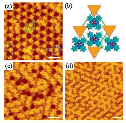
| Fig. 2. STM images showing the adsorption of FePc molecules at the hcp regions of SLG/Ru(0001) after full occupation of the fcc regions. (a) Additional FePc molecules adsorbed at the hcp regions, showing shift from the center of the regions. (b) A schematic illustrating the shift of additional FePc molecules adsorbed at the hcp regions (Orange triangles represent the atop regions). (c) Short molecular zigzag chains and hexagons around the atop regions are formed at coverage of ∼0.4 ML. (d) With increasing coverage, the molecular chains run along three equivalent directions of the substrate. Scanning parameters: (a) U = −2 V, I = 30 pA, (b) U = −2 V, I = 25 pA, (c) U = −2 V, I = 50 pA. The scale bar is 5 nm for each image. | |
The preferential adsorption of FePc molecules at the hcp regions rather than the atop regions is guided by the lower local work function of the hcp regions than that of the atop regions. However, the molecules are not located exactly at the center of the hcp regions. Instead, the molecules are shifted towards the atop regions due to the lateral dipole field along the atop-hcp direction [27]. As schematically described in Fig. 2b, the downwards arrow indicates the shift of FePc from the center of the hcp regions to the edge. Thus, FePc molecules at the hcp regions are attached to two nearby FePc molecules at the fcc regions, while separated from the third nearby FePc at the fcc region. There are three equivalent directions for this shift due to the three-fold symmetry of the substrate, as indicated in the three arrows and corresponding rhombuses in Fig. 2a. As more FePc molecules adsorbed at the hcp regions, hexagons or zigzag molecular chains are formed (Fig. 2c). With increasing coverage, the molecular chains become longer and the three-fold symmetry is more prominent, as seen in Fig. 2d.
At FePc coverage of ∼0.5 ML, a long-range ordered honeycomb superlattice with slight local distortion is formed, as shown in Fig. 3a. Each unit cell of the honeycomb lattice consists of two FePc molecules, with one molecule located at the fcc regions and the other at the hcp regions (see the rhombuses in Fig. 3a and b). Interestingly, while at a sample bias of 2 V the FePc molecules adsorbed at the fcc and the hcp regions look similar (Fig. 3a), at a sample bias of 3 V the central protrusions of the FePc molecules at the fcc regions are brighter than that at the hcp regions (Fig. 3b). As the central protrusions are originated from the dz2 orbital of the central Fe2+ ions [15], the different topographies of FePc molecules at the fcc and hcp regions suggest that the FePc molecules are coupled with the SLG/Ru(0001) substrate mainly through the central metal ions, in line with previous report [30]. The different electronic structures at the fcc and hcp regions result in a significant modification of the dz2 orbital of the central Fe2+ ions. Each atop region of the graphene moiré pattern is empty and surrounded by a molecular hexagon that consists of six FePc molecules located at the hcp and fcc regions. Thus, the periodicity of the honeycomb lattice replicates that of the SLG moiré pattern. Similar hexagonal network has also been observed in the system of CoPc on Fe/Co intercalated graphene [31]. However, when MPc are deposited on comparatively flat graphene such as graphene on Ir(111) or h-BN, mostly only square molecular lattices are obtained [31, 32].

|
Download:
|
| Fig. 3. STM images of FePc molecules forming honeycomb and Kagome lattice. STM image showing the formation of honeycomb lattice at FePc coverage of ∼0.5 ML at 2 V (a) and 3 V (b). The FePc molecules are located at the hcp and fcc regions, illustrating different apparent heights. Blue rhombuses indicate the unit cell of the moiré pattern and the white hexagons indicate the hexagonal lattice. (c) A schematic illustrating the hexagonal lattice. (d) FePc molecules forming Kagome lattice at a coverage ∼0.75 ML. Scanning parameters: (a) U = 2 V, I = 20 pA, (b) U = 3 V, I = 20 pA, (d) U = 2 V, I = 20 pA. The scale bar is 3 nm for each image. | |
Increasing FePc coverage to ∼0.75 ML, an additional FePc molecule is squeezed into the lower region of graphene moiré pattern in each unit cell, leading to a structural transition from a honeycomb lattice to a Kagome lattice (Fig. 3d) [8]. Each atop region of the graphene moiré pattern is empty and surrounded by a molecular hexagon that consists of six FePc located at the hcp and fcc regions, similar to that of the honeycomb lattice. However, such molecular hexagon is rotated by 30° with respect to that of the honeycomb lattice. This rearrangement of FePc molecules allows denser packing of molecules in the unit cell of graphene moiré pattern. Thus, each FePc molecule in the Kagome lattice has four nearest neighbors, larger than the coordination number of three for FePc molecule in the honeycomb lattice (the rhombus in Fig. 3b).
After the formation of a Kagome lattice, the hcp and fcc regions of SLG moiré pattern are fully occupied, leaving the atop regions entirely empty. These empty atop regions can be used as hosts to accommodate additional guest molecules. After addition of ∼0.01 ML FePc molecules upon the prepared Kagome lattice of FePc (a total coverage of ∼0.76 ML that includes a coverage of ∼0.75 ML for preparation of the FePc Kagome lattice), we observe the trapping of individual guest FePc molecules at the nanoscale pores of the FePc Kagome lattice [33]. The guest molecules adopt a flat configuration with their molecular planes parallel to the surface, as evidenced by the similar apparent height of their four lobes (Fig. 4a). While at the coverage of guest FePc molecules to ∼0.1 ML, each guest molecule appears as a pear-shaped protrusion, indicating that it adopts a tilted adsorption configuration. Besides, the pores of the Kagome lattice around the guest FePc molecules are greatly distorted (see the distorted hexagon marked in Fig. 4b). At a total coverage of ∼1 ML, the previous Kagome lattice is completely destroyed and the FePc molecules are rearranged into a close-packed square lattice with a lattice constant of ∼1 nm (inset in Fig. 4c). Square lattice was also reported for FePc monolayer on Au(111), however without the modulation of moiré pattern. The square lattice is modulated by the moiré pattern of SLG/Ru(0001), leading to a hexagonal superstructure with a period of ∼3 nm. Furthermore, the four-fold symmetry of the molecular layer is incommensurate with the six-fold symmetry of the SLG moiré pattern. Thus, a larger strip moiré pattern is formed after superposition of the square lattice of the molecular layer on the hexagonal lattice of SLG moiré pattern. The unit cell is a 1D strip, as shown in Fig. 4c.

|
Download:
|
| Fig. 4. STM images showing the formation of host-guest structures and close-packed monolayer of FePc molecules. (a) Individual guest FePc molecules are trapped at the pores of the FePc Kagome lattice with a flat adsorption configuration at a total coverage of ∼0.76 ML. (b) Host-guest superstructure of guest FePc molecules on FePc Kagome lattice at higher coverage, showing a distortion of FePc Kagome lattice. (c) Close-packed monolayer of FePc molecules with a square lattice. The interaction between the square lattice of the molecular adlayer and the hexagonal lattice of SLG moiré pattern leads to the formation of a strip superstructure. The inset shows the lattice vector of the unit cell of the molecular adlayer (blue arrows) and the hexagonal lattice of SLG moiré pattern (green arrows). Scanning parameters: (a) U = 1.5 V, I = 200 pA, (b) U = −2 V, I = 30 pA, (c) U = −2.5 V, I = 30 pA. The scale bar is 3 nm for (a-c) and 1 nm for the inset of (c). | |
We have systematically investigated the self-assembly of FePc molecules on SLG/Ru(0001) by means of LT-STM from submonolayer adsorption to the formation of close-packed monolayer. We observe the formation of single molecular arrays, ordered honeycomb lattice, Kagome lattice and square lattice with increasing coverage of FePc molecules. The densely packed square lattice of the molecular layer is modulated by the moiré pattern of SLG/Ru(0001). The superposition of the square lattice of the molecular layer on the hexagonal lattice of SLG moiré pattern leads to the formation of a larger strip moiré pattern. This coverage-dependent self-assembling behavior of FePc on SLG/Ru(0001) is mainly driven by the inhomogeneous electronic structure of graphene moiré pattern, due to the site-dependent interfacial charge transfer between SLG and Ru(0001) substrate. These results demonstrate that SLG moiré pattern can be used as a desirable template for fabrication of functional supramolecular nano-architectures with tunable structures and properties.
AcknowledgmentsFinancial support from the National Natural Science Foundation of China (No. 51661135026), Ministry of Science and Technology of China (Nos. 2015CB921103, 2016YFA0300904), and the Chinese Academy of Sciences is gratefully acknowledged.
| [1] |
J.V. Barth, G. Costantini, K. Kern, Nature 437(2005) 671-679. DOI:10.1038/nature04166 |
| [2] |
C. Joachim, J.K. Gimzewski, A. Aviram, Nature 408(2000) 541-548. DOI:10.1038/35046000 |
| [3] |
T. Yokoyama, S. Yokoyama, T. Kamikado, Y. Okuno, S. Mashiko, Nature 413(2001) 619-621. DOI:10.1038/35098059 |
| [4] |
H.J. Gao, L. Gao, Prog. Surf. Sci. 85(2010) 28-91. DOI:10.1016/j.progsurf.2009.10.001 |
| [5] |
K.J. Franke, G. Schulze, J.I. Pascual, Science 332(2011) 940-944. DOI:10.1126/science.1202204 |
| [6] |
Y.S. Fu, S.H. Ji, X. Chen, et al., Phys. Rev. Lett. 99(2007) 256601. DOI:10.1103/PhysRevLett.99.256601 |
| [7] |
L. Gao, W. Ji, Y.B. Hu, et al., Phys. Rev. Lett. 99(2007) 106402. DOI:10.1103/PhysRevLett.99.106402 |
| [8] |
J. Mao, H. Zhang, Y. Jiang, et al., J. Am. Chem. Soc. 131(2009) 14136-14137. DOI:10.1021/ja904907z |
| [9] |
Y.F. Wang, J. Kroger, R. Berndt, W.A. Hofer, J. Am. Chem. Soc. 131(2009) 3639-3643. DOI:10.1021/ja807876c |
| [10] |
A.D. Zhao, Q.X. Li, L. Chen, et al., Science 309(2005) 1542-1544. DOI:10.1126/science.1113449 |
| [11] |
L. Gao, Q. Liu, Y.Y. Zhang, et al., Phys. Rev. Lett. 101(2008) 197209. DOI:10.1103/PhysRevLett.101.197209 |
| [12] |
J.M. Gottfried, Surf. Sci. Rep. 70(2015) 259-379. DOI:10.1016/j.surfrep.2015.04.001 |
| [13] |
W. Auwarter, D. Ecija, F. Klappenberger, J.V. Barth, Nat. Chem. 7(2015) 105-120. DOI:10.1038/nchem.2159 |
| [14] |
J. Ahlund, J. Schnadt, K. Nilson, et al., Surf. Sci. 601(2007) 3661-3667. DOI:10.1016/j.susc.2007.06.008 |
| [15] |
Z.H. Cheng, L. Gao, Z.T. Deng, et al., J. Phys. Chem. C 111(2007) 2656-2660. DOI:10.1021/jp0660738 |
| [16] |
H. Karacuban, M. Lange, J. Schaffert, et al., Surf. Sci. 603(2009) L39-L43. DOI:10.1016/j.susc.2009.01.029 |
| [17] |
X. Lu, K.W. Hipps, X.D. Wang, U. Mazur, J. Am. Chem. Soc. 118(1996) 7197-7202. DOI:10.1021/ja960874e |
| [18] |
A. Scarfato, S.H. Chang, S. Kuck, et al., Surf. Sci. 602(2008) 677-683. DOI:10.1016/j.susc.2007.11.011 |
| [19] |
L. Liu, K. Yang, Y. Jiang, et al., Sci. Rep. 3(2013) 1210. DOI:10.1038/srep01210 |
| [20] |
L. Liu, K. Yang, Y. Jiang, et al., Phys. Rev. Lett. 114(2014) 126601. |
| [21] |
H. Dil, J. Lobo-Checa, R. Laskowski, et al., Science 319(2008) 1824-1826. DOI:10.1126/science.1154179 |
| [22] |
L. Liu, T. Dienel, R. Widmer, O. Gröning, ACS Nano 9(2015) 10125-10132. DOI:10.1021/acsnano.5b03741 |
| [23] |
I.P. Hong, N. Li, Y.J. Zhang, et al., Chem. Commun. 52(2016) 10338-10341. DOI:10.1039/C6CC03359H |
| [24] |
K.S. Novoselov, A.K. Geim, S.V. Morozov, et al., Science 306(2004) 666-669. DOI:10.1126/science.1102896 |
| [25] |
Y. Pan, H.G. Zhang, D.X. Shi, et al., Adv. Mater. 21(2009) 2777. DOI:10.1002/adma.200800761 |
| [26] |
H. Zhang, W.D. Xiao, J. Mao, et al., J. Phys. Chem. C 116(2012) 11091-11095. DOI:10.1021/jp3020244 |
| [27] |
H.G. Zhang, J.T. Sun, T. Low, et al., Phys. Rev. B 84(2011) 245436. DOI:10.1103/PhysRevB.84.245436 |
| [28] |
Y. Pan, D.X. Shi, H.J. Gao, Chin. Phys. 16(2007) 3151-3153. DOI:10.1088/1009-1963/16/11/001 |
| [29] |
H.G. Zhang, H. Hu, Y. Pan, et al., J. Phys.:Condens. Matter 22(2010) 302001. DOI:10.1088/0953-8984/22/30/302001 |
| [30] |
W. Dou, S. Huang, R.Q. Zhang, C.S. Lee, J. Chem. Phys. 134(2011) 094705. DOI:10.1063/1.3561398 |
| [31] |
M. Bazarnik, J. Brede, R. Decker, R. Wiesendanger, ACS Nano 7(2013) 11341-11349. DOI:10.1021/nn405172q |
| [32] |
P. Jarvinen, S.K. Hamalainen, K. Banerjee, et al., Nano Lett. 13(2013) 3199-3204. DOI:10.1021/nl401265f |
| [33] |
K. Yang, W.D. Xiao, Y.H. Jiang, et al., J. Phys. Chem. C 116(2012) 14052-14056. DOI:10.1021/jp304068a |