 2017, Vol. 28


b Department of Oral and Cranio-Maxillofacial, Ninth People's Hospital, Xinhua Hospital, Shanghai Jiao Tong University School of Medicine, Shanghai 200240, China
Electrical energy storage (EES) plays a key role in many applications such as portable electronics, electric vehicles, and devices for renewable energy storage from solar and wind [1-6]. Supercapacitors, one of the most important EES systems, have drawn great attentions because of their high power density, ultrafast charge-discharge rate and long cycle life [7, 8]. In a supercapacitor, the electrode materials are considered as the most important part because the electrical energy is stored by an ion adsorption and/or a redox reaction at the surface of the electrode. Considerable efforts have been devoted to developing qualified electrode materials to improve the capacitance [7, 9, 10]. Optimal electrode materials should be redox active materials with high surface area and good conductivity.
Covalent organic frameworks (COFs) are a class of crystalline porous polymers constructed by organic building blocks through covalent bonds into predictable, periodic two-or three-dimensional (2D or 3D) networks [11-16]. Just as metal-organic frameworks (MOFs) [17-20], COFs have also attracted much interest as promising materials for gas storage [21-23], catalysis [24-27], energy storage [28, 29], and other applications because of their designable periodical porous structure and reliable functionality. However, the electrical insulating nature of most COFs limits their application in optoelectronic and EES devices. To address this problem, using the hybrids of COFs and conductive agent is an efficient approach. These hybrids are usually prepared by mechanical mixing method.
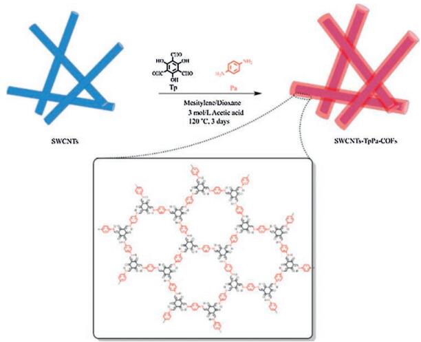
Here we demonstrate our strategy to prepare SWCNT-COF nano-hybrids by in situ polymerization of redox active TpPa-COFs together with SWCNTs under solvothermal conditions. TpPa-COFs were nano-coated onto SWCNTs to form a core-shell structure. One advantage over mechanical mixing method is that the COF/SWCNT interface can be better controlled at the molecular level [30]. Thus, the contact area between the COFs and SWCNTs was efficiently increased. The SWCNTs-TpPa-COFs-based electrodes provide improved electrochemical performance compared to those of TpPa-COFs-based supercapacitor electrodes reported in the literature [26, 27, 31, 32]. One reason why SWCNTs were selected as the conductive agent and the core part of the nano-hybrid is that the SWCNTs have high conductivity, high physical and chemical stability. The other important reason is that the π-π interaction between SWCNTs and COFs is beneficial for the COFs to grow and stack onto the SWCNTs and form the shell (Scheme 1).

|
Download:
|
| Scheme 1. Schematic diagram for the synthesis of SWCNTs-TpPa-COFs. | |
During the whole experiment, all the reagents were obtained from Aldrich. 1, 3, 5-triformylphloroglucinol (Tp) and TpPa-COF were synthesized according to previously reported procedure and characterizations matched well with that in the literature [33]. The Raman spectra were measured with 514 nm laser by a Raman microscope (inViaReflex, RENISHAW, England). Fourier-transform infrared (FT-IR) spectra were measured on Nicolet 6700 using KBr pieces. Powder X-ray diffraction (XRD) patterns were obtained with a RIGAKU diffractometer equipped with Cu Kα X-ray radiation. N2 sorption isotherms were measured on an accelerated surface area & porosimetrysystem, ASAP 2460 M + C (Micromeritics Instruments Inc.). Prior to analysis, the materials were solvent exchanged with THF using a Soxhlet washing procedure for 12 h. The powdered solid was loaded into a glass analysis tube and outgassed for 24 h under vacuum at 120 ℃. N2 adsorption and desorption isotherms were measured at 77 K and data was analysed using Brunauer-Emmett-Teller (BET) analysis models to determine the surface area. Field-emission SEM (FE-SEM) images were obtained using Sirion 200. High-resolution transmission electron microscopy (TEM) images were obtained using Talos F200X. Thermogravimetric analysis measurements were carried out on a PerkinElmer Pyris 1. Approximately 5 mg of sample was placed on a platinum pan, which was heated under a flow of N2 at a rate of 10 ℃/min up to 1000 ℃. Elemental analysis (EA) was conducted with Thermo Scientific Flash 2000.
TpPa-COFs wires incorporated with SWCNTs was synthesized under solvothermal condition. A 10 mL pyrex tube was charged with SWCNTs (56 mg) and a 3:2 molar ratio solution of p-phenylenediamine (Pa: 48 mg, 0.45 mmol) and 1, 3, 5-triformyl-phloroglucinol (Tp: 63 mg, 0.3 mmol) in a mixture of mesitylene/ 1, 4-dioxane/3 mol/L acetic acid (3.5 mL, 3:3:1). This mixture was sonicated for 30 min and degassed three times through freeze-pump-thaw cycles and sealed. The tube was kept in an oven at 120 ℃ for three days. The resulting powder was filtered and washed with mesitylene and acetone. Then the powder was collected and washed by employing THF as solvent using standard Soxhlet method to remove any impurities adsorbed in the porous structure. After being dried under vacuum at 120 ℃ for 24 h, SWCNTs-TpPa-COFs was obtained as a red solid.
To measure the electrochemical performances of the electrodes, the electrodes were tested by using a three-electrode device. A calomel electrode was used as the reference electrode, while a Pt electrode was used as the counter electrode. Meanwhile, a glassy carbon (GC) electrode was exploited as the work electrode. A slurry of SWCNTs-TpPa-COFs hybrids (35 wt%), carbon black (60 wt%), and polyvinylidene fluoride (PVDF, 5 wt%) was homogeneously painted on the surface of the GC electrode. The three electrodes were placed in 1 mol/L H2SO4 aqueous solution, which worked as the electrolyte. The cyclic voltammetry (CV) curves were performed at room temperature at the scan speed from 1 mV/s to 50 mV/s.
By utilizing the in situ polymerization of TpPa-COF together with SWCNT under solvothermal conditions, SWCNTs-TpPa-COFs wires were obtained as a red powder. As shown in field-emission scanning electron microscopy (FE-SEM) images and the transmission electron microscopy (TEM) image (Fig. 1), these SWCNTsTpPa-COFs wires are uniform with an average diameter of around 450 nm.

|
Download:
|
| Fig. 1. FE-SEM (a) and TEM (b) images of SWCNTs. (c)TEM image of TpPa-COFs. FE-SEM (d) and TEM (e) images of SWCNTs-TpPa-COFs. (f)FE-SEM image of SWCNTs-TpPa-COFs after 2000 cycles. | |
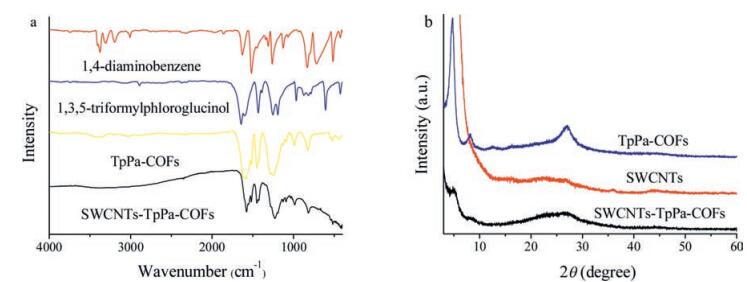
As shown in Fig. 2a, FT-IR spectrum of the SWCNTs-TpPa-COFs wires exhibited characteristic bands that are due to the β-ketoen-amine-linked TpPa-COF at 1243 cm-1 for the C—N stretching, 1584 cm-1 for the C=C stretching, and 1605 cm-1 for the C=O bond of the β-ketoenamine and appears in the spectrum of pure TpPa-COF, indicating the formation of TpPa-COF in the composite.

|
Download:
|
| Fig. 2. (a) FT-IR spectra of 1, 4-diaminobenzene (Pa) (red), triformylphloroglucinol (Tp) (blue), TpPa-COF (yellow) and SWCNTs-TpPa-COFs (black). (b) XRD patterns of the TpPa-COF (blue), SWCNT(red) and SWCNTs-TpPa-COFs wires (black). | |
To verify the existence of the TpPa-COFs, which was coated on the surface of the SWCNTs, we evaluated the Raman spectra of SWCNTs and SWCNTs-TpPa-COFs (Fig.S1 in Supporting information). There was an intense feature around 1588 cm-1 in spectra of each material, which was the in-plane vibrational (E2g) G band of the SWCNTs. The G band of SWCNTs-TpPa-COFs showed the existence of the SWCNTs. Two new bands at 1177 cm-1 and 1390 cm-1 indicated the characteristic peaks of the TpPa-COFs.
In addition, Powder XRD analysis was utilized to confirm the structure (Fig. 2b). The crystal structure of the AA stacking lattice and the ordered microporous channels of TpPa-COF in SWCNTs-TpPa-COFs wires can be indicated by two peaks at 4.7° and 8.3°, and a broad peak around 27°, which were assigned to the (100), (210) and (001) facets of TpPa-COF, respectively.
The nitrogen-gas (N2) adsorption at 77 K was obtained to estimate the permanent porosity of SWCNTs-TpPa-COFs wires, and the classic type Ⅰ isotherm obtained indicated the microporous characteristic of the composite (Fig. S2a in Supporting information). The BET surface area and Langmuir surface area were calculated to be 235.5 m2/g and 517.6 m2/g, respectively. Pore size distribution (Fig. S2b in Supporting information) profile was calculated using nonlocal density function theory. The pore size distributions of 1.1-5 nm, with peak maxima at 1.31 nm, was obtained.
The thermal stability of SWCNTs-TpPa-COFs wires was also investigated by thermogravimetric analysis (TGA). As shown in Fig. S3 (Supporting information), there was almost no obvious weight loss up to 350 ℃, demonstrating the excellent thermal stability of SWCNTs-TpPa-COFs composite. The chemical stability test (Fig. S4 in Supporting information) was performed by soaking SWCNTs-TpPa-COFs wires in different solvents (hexane, o-DCB, DMF, THF, methanol and water) for seven days at room temperature. The Powder XRD patterns were maintained after the test, revealing the great chemical stability in those organic solvents.
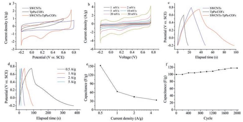
Futhermore, the electrochemical performance was measured. In the CV test, the cyclic process was performed under the scan rate from 1 mV/s to 50 mV/s. It could be found that the shape of the curves was retained with the increase of the scan rate, indicative of the quick transfer of electrons between the glassy electrodes and composite [28]. Fig. 3a displayed the CV curves of electrodes made from SWCNTs, TpPa-COFs and SWCNTs-TpPa-COFs wires, respectively. The area of the curve, which was provides by SWCNTs-TpPa-COFs wires, was significantly larger than that of TpPa-COFs. It suggested that the composite possessed much larger capacitance. The whole CV curves (Fig. 3b) tended to fit the rectangle shape, which indicated that the electronic double-layer capacitance played an important role in the specific capacitance [34, 35]. A reversible redox pair was observed on each CV curve. The oxidation and reduction peaks arose at around 0.25 V and 0.15 V, respectively. The redox peaks indicated the existence of the faradaic pseudocapacitance [34, 36]. With the increase of the scan rate, the redox peaks maintain the position. The stability also attributed to the fast and reversible electron transfer between the electrolyte and the electrode [37].
The high specific surface area, abundant redox groups and good conductivity are of interest for both electrochemical double-layer and pseudocapacitive capacitance. To evaluate the specific capacitance of the SWCNTs, TpPa-COFs and the SWCNTs-TpPa-COFs wires, we performed galvanostatic charge-discharge (GCD) experiments at the current densities of 1 A/g (Fig. 3c). In each experiment, we applied a constant current to the electrode. Corresponding to the result in Fig. 3a, the electrode based on as-designed SWCNTs-TpPa-COFs deliver a much higher capacitance. To be specific, the specific capacitance of the composite was 7.7 times of that of TpPa-COFs. The voltage-time curve of the GCD put up typical "shark-fin" profiles, which was related to the doublelayer pseudocapacitive [28]. In line with the CV images, the GCD curves possessed obvious plateaus at around 0.2 V. The highest specific capacitance was 153 F/g at the current density of 0.5 A/g [28], suggesting great ability of energy storage [34, 38, 39]. However, the capacitance decreased apparently with the current density increase (Fig. 3e).

|
Download:
|
| Fig. 3. (a) CV images of electrodes based on the SWCNTs (blue), TpPa-COFs (black) and SWCNTs-TpPa-COFs wires (red) at 20 mV/s in 1 mol/L H2SO4. (b) CV images of SWCNTs-TpPa-COFs-based electrode at different scan rates from 1 mV/s to 50 mV/s. (c) Galvanostatic charge/discharge curves of the electrodes based on the SWCNTs(blue), TpPa-COFs (black) and SWCNTs-TpPa-COFs wires(red) at 1 A/g. (d) Galvanostatic charge/discharge curves of the SWCNTs-TpPa-COFs-based electrode at different current densities. (e) Corresponding specific capacitance of SWCNTs-TpPa-COFs based electrode at various current densities. (f) Cyclic charge/discharge performance of the SWCNTs-TpPa-COFs-based electrode at 2 A/g | |
Besides, the cyclic stability is another essential factor to reveal the electrochemical performance of the supercapacitor electrodes [29]. We measured the specific capacitance during the 2000 cyclic charge/discharge process (Fig. 3f) at the constant current density of 2 A/g. The capacitance of the electrode based on the as-designed SWCNTs-TpPa-COFs wires maintained stable during the cyclic charge/discharge process. The slight augment of the specific capacitance is attributed to the process, which increased the contact area between the electrolyte and the electrodes [38, 40, 41].
Moreover, electrochemical impedance spectroscopy (EIS) was measured to reveal the internal resistance and ion transport ability of SWCNTs-TpPa-COFs wires. The experiment was carried out by evaluating the response of the SWCNTs-TpPa-COFs towards the frequency varying from 0.01 Hz to 100, 000 Hz (Fig. S5 in Supporting information). The equivalent series resistance (Rs), which is 4.9Ω, was revealed by the intercept between the impedance spectrum and real impedance axis (Z') [33, 42]. The oblique line in low frequency is responsible for the shuttle behavior of the ions [40]. Besides, the Bode plots (Fig. S6 in Supporting information) was also exhibited to evaluate the frequency features of the composite. The -45° sloped plots of the Nyquist plots plays the most important role. The section of the slope above -45° represented the high frequency part of the Nyquist curve, in which, the electrode mainly showed resistive activity. In contrast, the electrode was capacitive active in the section from -90° to -45°, which covered the most part of the Bode plots [43, 44].
The system frequency f0 of SWCNTs-TpPa-COFs wires was 140 Hz. The response time τ0 was calculated to be 0.0071 s by the equation:

|
Where f0 is the characteristic frequency when the angle is -45°, τ0 is the relaxation time constant [45].
The swift response time exhibited the low resistance and good electrochemical performances of the electrodes based on the asdesigned SWCNTs-TpPa-COFs wires.
In summary, TpPa-COFs have been successfully nano-coated onto SWCNTs through an in situ polymerization under solvothermal conditions. By combining the high conductivity of the SWCNTs and the high porosity and redox groups of the TpPa-COFs, the nano-hybrid-based electrode delivered a specific capacitance of 153 F/g at the current density of 0.5 A/g and ultra-long cycling stability. The excellent electrochemical performance enables the SWCNTs-TpPa-COFs nano-hybrid wires practically very competitive for supercapacitors. The facile synthetic approach and unique nanostructure design may be extended to other COFs for highperformance supercapacitor energy storage. In addition, the results demonstrate the promise of using COFs-SWCNTsnanohybrid for supercapacitor energy storage.
AcknowledgmentsThis work is supported by the National Natural Science Foundation of China (Nos. 61774102, 81670958), the Shanghai Pujiang Program (No.16PJD027), and the Interdisciplinary Program of Shanghai Jiao Tong University (Nos. YG2015MS23, YG2016MS71). We also thank the analysis support from the Instrumental Analysis Center of Shanghai Jiao Tong University.
Appendix A. Supplementary dataSupplementary data associated with this article can be found, in the online version, at https://doi.org/10.1016/j.cclet.2017.10.024.
| [1] |
Z.W. Seh, Y. Sun, Q. Zhang, Y. Cui, Chem. Soc. Rev. 45(2016) 5605-5634. DOI:10.1039/C5CS00410A |
| [2] |
S.D. Brucks, D.N. Bunck, W.R. Dichtel, Polymer 55(2014) 330-334. DOI:10.1016/j.polymer.2013.07.030 |
| [3] |
X. Zhang, G. Zhu, M. Wang, et al., Carbon 116(2017) 686-694. DOI:10.1016/j.carbon.2017.02.057 |
| [4] |
S. Chai, H. Liu, X. Zhang, et al., Appl. Surf. Sci. 384(2016) 539-543. DOI:10.1016/j.apsusc.2016.05.068 |
| [5] |
X. Ren, L. Lu, Chin. Chem. Lett. 26(2015) 1439-1445. DOI:10.1016/j.cclet.2015.10.014 |
| [6] |
Z. Deng, H. Jiang, Y. Hu, et al., Adv. Mater. 29(2017) 1603020. DOI:10.1002/adma.201603020 |
| [7] |
Y. Wang, Y. Song, Y. Xia, Chem. Soc. Rev. 45(2016) 5925-5950. DOI:10.1039/C5CS00580A |
| [8] |
H. Jiang, P.S. Lee, C. Li, Energy Environ. Sci 6(2013) 41-53. DOI:10.1039/C2EE23284G |
| [9] |
Y. Wang, Z. Shi, Y. Huang, et al., J. Phys. Chem. C 113(2009) 13103-13107. DOI:10.1021/jp902214f |
| [10] |
H. Wang, F. Jiao, F. Gao, et al., Talanta 166(2017) 133-140. DOI:10.1016/j.talanta.2017.01.043 |
| [11] |
X. Feng, X. Ding, D. Jiang, Chem. Soc. Rev. 41(2012) 6010-6022. DOI:10.1039/c2cs35157a |
| [12] |
S.Y. Ding, W. Wang, Chem. Soc. Rev. 42(2013) 548-568. DOI:10.1039/C2CS35072F |
| [13] |
N.W. Ockwig, A.P. Cote, M.O. Keeffe, A.J. Matzger, O.M. Yaghi, Science 310(2005) 1166-1171. DOI:10.1126/science.1120411 |
| [14] |
M. Wu, G. Chen, J. Ma, P. Liu, Q. Jia, Talanta 161(2016) 350-358. DOI:10.1016/j.talanta.2016.08.041 |
| [15] |
Q. Sun, B. Aguila, J. Perman, et al., J. Am. Chem. Soc. 139(2017) 2786-2793. DOI:10.1021/jacs.6b12885 |
| [16] |
F. Xu, D. Wu, R. Fu, B. Wei, Mater. Today (2017), doi: http://dx.doi.org/10.1016/j.mattod.2017.04.026.
|
| [17] |
L. Ma, S. Wang, X. Feng, B. Wang, Chin. Chem. Lett. 27(2016) 1383-1394. DOI:10.1016/j.cclet.2016.06.046 |
| [18] |
H. Wang, H. Ding, X. Meng, C. Wang, Chin. Chem. Lett. 27(2016) 1376-1382. DOI:10.1016/j.cclet.2016.05.020 |
| [19] |
M.X. Wu, Y.W. Yang, Chin. Chem. Lett. 27(2017) 1376-1382. |
| [20] |
L. Yang, D.C. Wei, Chin. Chem. Lett. 7(2016) 1395-1404. |
| [21] |
Y. Zeng, R. Zou, Y. Zhao, Adv. Mater. 28(2016) 2855-2873. DOI:10.1002/adma.201505004 |
| [22] |
N. Huang, R. Krishna, D. Jiang, J. Am. Chem. Soc. 137(2015) 7079-7082. DOI:10.1021/jacs.5b04300 |
| [23] |
H. Wei, S. Chai, N. Hu, et al., Chem. Commun. 51(2015) 12178-12181. DOI:10.1039/C5CC04680G |
| [24] |
S.Y. Ding, J. Gao, Q. Wang, et al., J. Am. Chem. Soc. 133(2011) 19816-19822. DOI:10.1021/ja206846p |
| [25] |
Y. Wu, H. Xu, X. Chen, J. Gao, D.L. Jiang, Chem. Commun. 51(2015) 10096-10098. DOI:10.1039/C5CC03457D |
| [26] |
H. Xu, J. Gao, Nat. Chem. 7(2015) 1-50. DOI:10.1038/nchem.2143 |
| [27] |
J. Li, X. Xu, X. Liu, et al., J. Alloys Compd. 690(2017) 640-646. DOI:10.1016/j.jallcom.2016.08.176 |
| [28] |
C.R. DeBlase, K.E. Silberstein, T.T. Truong, H.D. Abruña, W.R. Dichtel, J. Am. Chem. Soc.(2013), 8-11. |
| [29] |
F. Xu, H. Xu, X. Chen, et al., Angew. Chem. Int. Ed. 54(2015) 6814-6818. DOI:10.1002/anie.201501706 |
| [30] |
H. Wang, H. Jiang, Y. Hu, et al., Chem. Eng. Sci. 174(2017) 104-111. DOI:10.1016/j.ces.2017.09.007 |
| [31] |
Y.B. Huang, P. Pachfule, J.K. Sun, Q. Xu, J. Mater. Chem. A 4(2016) 4273-4279. DOI:10.1039/C5TA10170K |
| [32] |
Z. Zha, L. Xu, Z. Wang, et al., ACS Appl. Mater. Interfaces 7(2015) 17837-17843. DOI:10.1021/acsami.5b04185 |
| [33] |
Y. Han, N. Hu, S. Liu, et al., Nanotechnology 8(2017) 33LT01. |
| [34] |
Y. Liu, Y. Ma, S. Guang, H. Xu, X. Su, J. Mater. Chem. A 2(2014) 813-823. DOI:10.1039/C3TA13513F |
| [35] |
Z. Liu, K. Xiao, H. Guo, et al., Carbon 117(2017) 163-173. DOI:10.1016/j.carbon.2017.02.087 |
| [36] |
X. Deng, J. Li, S. Zhu, et al., J. Alloys Compd. 693(2017) 16-24. DOI:10.1016/j.jallcom.2016.09.096 |
| [37] |
S.X. Sun, L.H. Ma, C. Cheng, et al., Phys. Status Solidi A(2017), 1700322. |
| [38] |
M. Yu, W. Wang, C. Li, et al., NPG Asia Mater. 6(2014) e129. DOI:10.1038/am.2014.78 |
| [39] |
P. Yu, X. Zhao, Z. Huang, Y. Li, Q. Zhang, J. Mater. Chem. A 2(2014) 14413-14420. DOI:10.1039/C4TA02721C |
| [40] |
S. Chai, N. Hu, Y. Han, et al., RSC Adv. 6(2016) 49425-49428. DOI:10.1039/C6RA08536A |
| [41] |
L. Wang, Y. Ye, X. Lu, et al., Sci. Rep. 3(2013) 3568. DOI:10.1038/srep03568 |
| [42] |
B. Gao, H. Zhou, J. Yang, Appl. Surf. Sci. 409(2017) 350-357. DOI:10.1016/j.apsusc.2017.03.015 |
| [43] |
D.P. Dubal, S.H. Lee, J.G. Kim, W.B. Kim, C.D. Lokhande, J. Mater. Chem. 22(2012) 3044-3052. DOI:10.1039/c2jm14470k |
| [44] |
B.G. Choi, J. Hong, W.H. Hong, P.T. Hammond, H. Park, ACS Nano 5(2011) 7205-7213. DOI:10.1021/nn202020w |
| [45] |
D. Pech, M. Brunet, H. Durou, et al., Nat. Nanotechnol. 5(2010) 651-654. DOI:10.1038/nnano.2010.162 |