 2017, Vol. 28


b State Key Laboratory of Fire Science, University of Science and Technology of China, Hefei 230026, China
Lithium-ion batteries (LIBs) have been widely used in portable devices and energy storage systems due to their high energy density, light weight and long cycle life [1]. It is well known that graphite is the most conventional anode material for LIBs, but it shows a limited theoretical capacity of 372 mAh/g, which is unable to meet the demand for electric vehicles (EVs) and large-scale energy storage systems [2]. Recently, much effort has been devoted to find new materials with high capacity, good rate capability and good cycling stability to replace graphite anode [3-9]. Molybdenum trioxide (MoO3) with a high theoretical specific capacities of 1117 mAh/g, has been regarded as a promising candidate of traditional graphite for next-generation LIBs. However, MoO3 suffers from serious capacity fading and poor rate capability due to the large volume change, the aggregation of the transition nanoparticles during lithiation/delithiation process and low intrinsic electronic conductivity gravely affected its applications [10]. Decreasing the size of MoO3 particles has been demonstrated as an effective strategy to improve the electrochemical performances of MoO3, because the nanosized particles could shorten the diffusion length of Li ions and mitigate the volume variation of the electrode during Li ions intercalation and deintercalation process. Nanosized MoO3 particles with different morphologies including nanoparticles [11], nanowires [12], nanobelts [13] have been reported, showing improve lithium storage performance. Among these morphologies, one dimensional (1D) nanostructure allows for better accommodation of the huge volume changes, leading to fracture free structure after repeated cycles. In addition, 1D nanostructure could provide fast charge transport pathway for both ions and electrons [14-16]. Designing of porous structure and carbon coating are another most popular strategy to improve the electrochemical performances of MoO3 [17].
Graphene is a 2D carbon material with high surface area, chemical stability, and outstanding electronic conductivity, exhibiting excellent energy storage performance [18]. Meanwhile, reduced graphene oxide (rGO) shows an excellent electric conductivity, which has been applied to enhance electric conductivity of electrode materials [4, 6, 19, 20]. Designing graphene coated 1D MoO3 should be a promising approach to realize high performance lithium storage. Recently, metal-organic frameworks (MOFs) with unique characteristics have been widely studied [21-23]. MOFs have been used as templates and precursors to synthesize various porous nanomaterials [24-26]. Herein, we designed and synthesized reduced graphene oxide wrapped hollow molybdenum trioxide nanorods (denoted as MoO3@rGO) by simply mixing molybdenum-based MOFs (Mo-MOFs) with graphene oxide (GO) followed by a two-step annealing process. When used as anode material in LIBs, the MoO3@rGO shows a high reversible capacity (842 mAh/g at 0.1 A/g), excellent cycling stability (778 mAh/g at 0.1 A/g after 200 cycles) and excellent rate capability (455 mAh/g at 2 A/g).
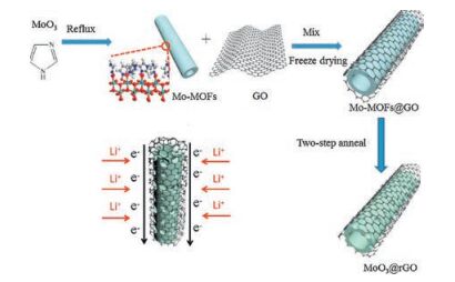
The entire fabrication process was shown in Scheme 1. Firstly, the synthesis of Mo-MOFs was followed by Pedro Martin-Zarza's work [27]: 3.5 g of MoO3 and 1.66 g of imidazole were seriatim mixed in 500 mL of deionized water. And then the mixture was refluxed at 80 ℃ for 12 h in an oil bath, the precipitate were separated by centrifugation at 6000 rpm for 2 min, rinsed with deionized water for three times. After drying in an oven at 60 ℃ overnight, the Mo-MOFs were obtained. Then, 0.2 g of Mo-MOFs were mixed with 4 mL GO aqueous solution (~5 mg/mL, pH 1), the mixture was stirred for 6 h. After that the mixture was frozen by liquid nitrogen, and then the frozen sample was transferred to a vacuum freeze dryer immediately. A two-step annealing process had been taken to fabricate MoO3@rGO. Firstly, the composite of Mo-MOFs and GO was annealed at 600 ℃ for 6 h with a heating rate of 3 ℃/min in N2 to get MoO2@rGO. And the MoO3@rGO can be obtained by the further annealing of MoO2@rGO under air at 300 ℃ for 3 h with heating rate of 5 ℃/min. For comparison, pure MoO3 without GO was synthesized by the same experimental conditions.

|
Download:
|
| Scheme 1. Schematic illustration of the fabrication processes of MoO3@rGO and schematic diagram of lithium ion diffusion and electron conduction in MoO3@rGO. | |
The battery performance of the electrodes was assessed with CR2032 coin cells. The working electrodes were prepared by the doctor-blade coating of the slurry onto a copper foil. The slurry was formed of active material, acetylene black and polyvinylidene fluoride (PVDF) with a weight ratio of 80:10:10. N-Methyl-2-pyrrolidone (NMP) was employed to adjust the viscosity of the slurry. The diameter of electrode slice is 1 cm and the average mass of the electrode slice is about 1.2 mg, so the loading amount of the electrodes is about 1.5 mg/cm2. To assemble Li-ion batteries, a Li foil was utilized as counter electrode. The celgard 2400 fibre was used as a separator. The electrolyte was 1 mol/L LiPF6 dissolved in a mixture of ethylene carbonate (EC) and diethyl carbonate (DEC) in a volume ratio of 1:1. The cyclic voltammogram (CV) measurements were performed on CHI 660D electrochemical workstation at a scan rate of 0.2 mV/s. Charge/discharge (0.01-3.0 V) tests were performed on a Neware BTS-610 battery test system under room temperature.
The morphologies of Mo-MOFs, pure MoO3 and MoO3@rGO were characterized by Scanning electron microscopy (SEM) (JEOL, Tokyo, Japan) (Fig. 1). Fig. 1a shows the SEM image of the Mo-MOFs. The Mo-MOFs display nanorods morphology with a size of 200-500 nm in diameter and 5-30 mm in length. The SEM images of the pure MoO3 and MoO3@rGO are presented in Figs. 1b-d. Both of the MoO3 and MoO3@rGO keep the structure of nanorod, while the MoO3 is composed of many small particles. After coating of reduce graphene oxide (rGO), the nanorod structure of the MoO3@rGO keep intact. Fig. 1d is the enlarged view of the marked part in Fig. 1c. As marked in Fig. 1d, there are two gaps, which suggesting a hollow structure of the nanorod. To further reveal the morphology of MoO3@rGO, Transmission electron microscopy (TEM) (JEOL, Tokyo, Japan) was conducted. Fig. 2a confirms the hollow structure of the nanorod. Moreover, rGO film completely wrapped the surface of the MoO3 nanorod. In addition, a number of pores can be observed in the wall of the hollow nanorod. The phase purity and crystallinity of MoO3@rGO was characterized by X-ray diffraction (XRD) (Philips X'PertPRO SUPER X-ray diffractormeter). As shown in Fig. 2b, all of the XRD peaks of MoO3@rGO can agree well with α-MoO3 (JCPDS 05-0508) while there is no impure peak can be observed, indicating a good phase purity and crystallinity of MoO3. Raman spectroscopy was also performed (Fig. 2c). Several peaks can be found at 200-1000 cm-1, which attributed to the stretching and bending of Mo-O bonds, in agreement with previous reports [28, 29]. The typical Raman peaks of D and G bands of rGO can also be observed at 1366 and 1601 cm-1 respectively, confirming the presence of rGO [4]. The surface chemistry of the MoO3@rGO was analyzed by X-ray photoelectron spectroscopy (XPS). Fig. 2d shows the wide scan XPS survey spectrum, indicating that the MoO3@rGO only contains C, Mo and O elements. The individual spectrum of Mo 3d is shown in Fig. 2e, there are two peaks located at 232.9 and 236.1 eV with an integrated peak area ratio of 3:2, corresponding to Mo(Ⅵ) for MoO3 [30]. As for the spectrum of C 1s (Fig. 2f), expect the C-C bond at 284.8 eV, different oxygen-containing functional groups of the C-O bond at 286.2 eV, the C=O bond at 288.9 eV can also be observed [31].

|
Download:
|
| Fig. 1. SEM images of Mo-MOFs (a), pure MoO3 (b), MoO3@rGO (c, d). | |

|
Download:
|
| Fig. 2. (a) TEM image, (b) XRD pattern, (c) Raman spectra and (d) XPS spectra of MoO3@rGO. XPS spectra of (e) Mo 3d and (f) C 1s of MoO3@rGO. | |
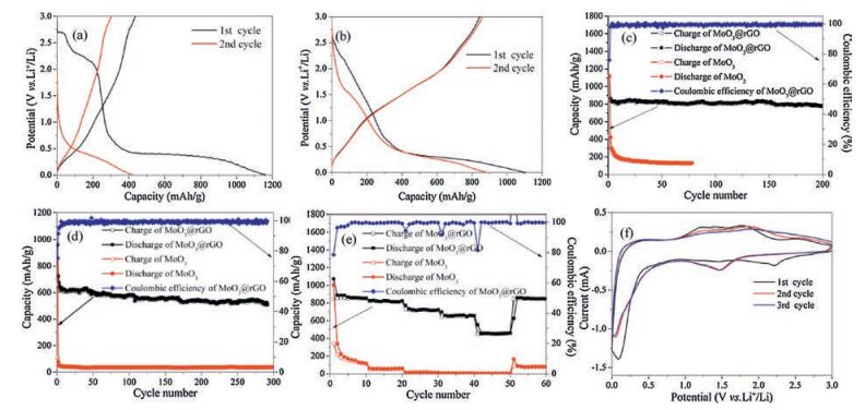
To evaluate the electrochemical performance of the MoO3@rGO, galvanostatic charge/discharge measurements and cyclic voltammetry (CV) were performed. For comparison, we also measured galvanostatic charge/discharge of the pure MoO3. Fig. 3a and b display the initial two galvanostatic discharge-charge profiles of the pure MoO3 and MoO3@rGO at a current density of 100 mA/g between 0.01 V and 3 V. The pure MoO3 delivers capacities of 1st discharge and 1st charge are 1163 mAh/g and 436 mAh/g, respectively, corresponding an initial coulombic efficiency (ICE) of 37%. For MoO3@rGO, it shows an initial discharge capacity of 1107 mAh/g and an initial charge capacity of 842 mAh/g with an ICE of 76%. The decomposition of electrolyte and the formation of solid electrolyte interface (SEI) are responsible for the low ICE of MoO3@rGO [32]. The MoO3@rGO also delivers an excellent cycling stability and rate performance (Figs. 3c-e). Cycling performances of the MoO3@rGO and pure MoO3 at current density of 100 mA/g were shown in Fig. 3c. The charge capacity of MoO3@rGO can maintain 778 mAh/g after 200 cycles showing a capacity retention of 92%, while the pure one can only retain reversible capacity of 148 mAh/g after 30 cycles. The long cycling stability of the two electrodes was further studied at a high current density of 1 A/g (Fig. 3d). The MoO3@rGO electrode shows a capacity of 653 mAh/g for first charge and delivers reversible capacity of 522 mAh/g after almost 300 cycles with a capacity retention of 80%. In case of the MoO3, it displays an initial charge capacity of 109 mAh/g, subsequently it drops rapidly probably, which maybe due to the structure collapse of MoO3. Rate performance of the MoO3@rGO and pure MoO3 were also measured. As shown in Fig. 3e, the MoO3@rGO electrode exhibits a high reversible capacity of 843, 821, 722, 652, 455 mAh/g at 0.1, 0.2, 0.5, 1.0, 2.0 A/g, respectively, while the pure MoO3 shows 341, 56, 16, 7, 4 mAh/g at the same current density. The specific capacity of the MoO3@rGO was recovered when the current density was turned back to 0.1 A/g, indicating the reversible lithium storage in the MoO3@rGO. To investigate the structural and electrochemical information of MoO3@rGO electrode during the lithium ions insertion/extraction process, cyclic voltammetry of a fresh cell of it at a scan rate of 0.2 mV/s was performed (Fig. 3f). In the first cathodic scan, the obvious peak at 2.2 V is attributed to the initial reaction of lithium-ion insertion into the crystalline α-MoO3-layered structure, which can be expressed as the following equation [11, 31, 33, 34]:

|
Download:
|
| Fig. 3. Potential-capacity curves at 100 mA/g of (a) pure MoO3 and (b) MoO3@rGO. Comparing of cycling performances of the two electrodes at (c) 100 mA/g and (d) 1 A/g. (e) Rate capability at different current densities (increased from 0.1 A/g to 2 A/g) and (f) CV curves of MoO3@rGO. | |

|
(1) |
Another strong peak occurred at around 0.2 V can be indicated as a conversion reaction of LixMoO3 to form Li2O and disordered Mo metal, and the formation of SEI layer [32, 35-37]:

|
(2) |
As for the initial anodic scan, a wide peak located at 0.8-2.3 V, which related to the reverse reaction of Eq. (2) [30, 38]. After the first cycle, the curves of the following two cycles were almost overlapped, further confirming an excellent cycle stability of the MoO3@rGO electrode. A new peak appears at 1.5 V after the initial cycle can be assigned to the electrochemical reaction of MoO2, suggesting the formation of the intermediate phase MoO2 [39, 40].
Electrochemical impedance spectroscopy (EIS) of both MoO3@rGO and pure MoO3 electrodes was carried out. Figs. 4a and b present the Nyquist plots of the two electrodes before cycled and after 10 cycles at 500 mA/g, respectively. All curves comprise a depressed semicircle in the high-middle frequency region related to the charge transfer impedance and a straight line in the low frequency correlation with the lithium ion diffusion [41, 42]. As the diameter of the semicircle can approximately reflect the charge transfer impedance [43], both fresh cell and after cycled cell of MoO3@rGO show smaller impedance than those of the MoO3, indicating a better electronic conductivity of MoO3@rGO electrode. Meanwhile, the square of the slope of the straight line of the relationship between Zre and ω-1/2 in the low frequency region is inversely proportional to the diffusion coefficient of lithium ions in anode material [44]. As shown in Fig. 4c and d, both of the fresh cell and the cell after cycled of MoO3@rGO display a lesser slope than the pure MoO3, suggesting a better lithium-ion diffusion coefficient of the MoO3@rGO electrode. Furthermore, the impedances become smaller when the cells after cycled, which can be related to the destruction of passivation layer on the lithium metal surface and the formation of a new surface [45].

|
Download:
|
| Fig. 4. The Nyquist plots of MoO3@rGO and pure MoO3 (a) before cycled and (b) after 10 cycles. The relationship between Zre and ω-1/2 in the low frequency region of MoO3@rGO and pure MoO3 (c) before cycled and (d) after 10 cycles. | |
In summary, the MoO3@rGO hollow nanorod was fabricated by using the Mo-based metal-organic frameworks and graphite oxide as raw materials through freeze drying and a two-step annealing process. When used as the anode material for lithium-ion batteries, the MoO3@rGO electrode exhibits excellent electrochemical performances (842 mAh/g at the rate of 100 mA/g) and long cycle life (778 mAh/g after 200 cycles). The excellent electrochemical performance demonstrates that the hollow structure, pores in the wall and rGO coating could act as buffer to tolerate volume expansion of the MoO3, improve the electronic conductivity, and enhances structural stability and cyclability.
AcknowledgmentsThis work was financially supported by the National Key R&D Program of China (No. 2016YFB0100305), the National Natural Science Foundation of China (Nos. 21373195, 51622210), the Fundamental Research Funds for the Central Universities (No. WK3430000004), the Collaborative Innovation Center of Suzhou Nano Science and Technology.
| [1] |
B. Scrosati, Nature 373(1995) 557-558. DOI:10.1038/373557a0 |
| [2] |
J.M. Tarascon, M. Armand, Nature 414(2001) 359-367. DOI:10.1038/35104644 |
| [3] |
C. Yang, W. Li, Z. Yang, L. Gu, Y. Yu, Nano Energy 18(2015) 12-19. DOI:10.1016/j.nanoen.2015.09.008 |
| [4] |
X. Liu, J. Cheng, W. Li, et al., Nanoscale 6(2014) 7817-7822. DOI:10.1039/c4nr01493f |
| [5] |
X. Zhong, Z. Yang, X. Liu, et al., ACS Appl. Mater. Interfaces 7(2015) 18320-18326. DOI:10.1021/acsami.5b03942 |
| [6] |
X. Zhong, J. Wang, W. Li, et al., RSC Adv. 4(2014) 58184-58189. DOI:10.1039/C4RA08797F |
| [7] |
J. Liu, X. Xu, R. Hu, L. Yang, M. Zhu, Adv. Energy Mater. 6(2016) 1600256. DOI:10.1002/aenm.201600256 |
| [8] |
X. Xu, J. Liu, Z. Liu, et al., ACS Nano 11(2017) 9033-9040. DOI:10.1021/acsnano.7b03530 |
| [9] |
L. Yu, J. Liu, X. Xu, et al., ACS Nano 11(2017) 5120-5129. DOI:10.1021/acsnano.7b02136 |
| [10] |
M. Zhou, M.L. Gordin, S. Chen, et al., Electrochem. Commun. 28(2013) 79-82. DOI:10.1016/j.elecom.2012.12.013 |
| [11] |
S.H. Lee, Y.H. Kim, R. Deshpande, et al., Adv. Mater. 20(2008) 3627-3632. DOI:10.1002/adma.v20:19 |
| [12] |
P. Meduri, E. Clark, J.H. Kim, et al., Nano Lett. 12(2012) 1784-1788. DOI:10.1021/nl203649p |
| [13] |
Z. Wang, S. Madhavi, X.W. Lou, J. Phys. Chem. C 116(2012) 12508-12513. DOI:10.1021/jp304216z |
| [14] |
S. Lim, C.S. Yoon, J. Cho, Chem. Mater. 20(2008) 4560-4564. DOI:10.1021/cm8006364 |
| [15] |
Y. Cao, L. Xiao, M.L. Sushko, et al., Nano Lett. 12(2012) 3783-3787. DOI:10.1021/nl3016957 |
| [16] |
Y. Li, B. Tan, Y. Wu, Nano Lett. 8(2008) 265-270. DOI:10.1021/nl0725906 |
| [17] |
T. Tao, A.M. Glushenkov, C. Zhang, et al., J. Mater. Chem. 21(2011) 9350-9355. DOI:10.1039/c1jm10220f |
| [18] |
X. Huang, X. Qi, F. Boey, H. Zhang, Chem. Soc. Rev. 41(2012) 666-686. DOI:10.1039/C1CS15078B |
| [19] |
C. Petit, T.J. Bandosz, Adv. Mater. 21(2009) 4753-4757. DOI:10.1002/adma.200901581 |
| [20] |
J. Zhu, D. Lei, G. Zhang, et al., Nanoscale 5(2013) 5499-5505. DOI:10.1039/c3nr00467h |
| [21] |
H.K. Chae, M. Eddaoudi, J. Kim, et al., J. Am. Chem. Soc. 123(2001) 11482-11483. DOI:10.1021/ja011692+ |
| [22] |
G. Lu, S. Li, Z. Guo, et al., Nat. Chem. 4(2012) 310-316. DOI:10.1038/nchem.1272 |
| [23] |
S. Hermes, M.K. Schröter, R. Schmid, et al., Angew. Chem. Int. Ed. 117(2005) 6394-6397. DOI:10.1002/(ISSN)1521-3757 |
| [24] |
K.E. DeKrafft, C. Wang, W. Lin, Adv. Mater. 24(2012) 2014-2018. DOI:10.1002/adma.201200330 |
| [25] |
B. Liu, H. Shioyama, T. Akita, Q. Xu, J. Am. Chem. Soc. 130(2008) 5390-5391. DOI:10.1021/ja7106146 |
| [26] |
X. Xu, R. Cao, S. Jeong, J. Cho, Nano Lett. 12(2012) 4988-4991. DOI:10.1021/nl302618s |
| [27] |
P. Martin-Zarza, J. Arrieta, M. Munoz-Roca, P. Gili, J. Chem. Soc. Dalton Trans.(1993), 1551-1557. |
| [28] |
L.Q. Mai, B. Hu, W. Chen, et al., Adv. Mater. 19(2007) 3712-3716. DOI:10.1002/(ISSN)1521-4095 |
| [29] |
V. Kumar, A. Sumboja, J. Wang, et al., Chem. Mater. 26(2014) 5533-5539. DOI:10.1021/cm502558t |
| [30] |
C.L. Liu, Y. Wang, C. Zhang, X.S. Li, W.S. Dong, Mater. Chem. Phys. 143(2014) 1111-1118. DOI:10.1016/j.matchemphys.2013.11.011 |
| [31] |
F. Ma, A. Yuan, J. Xu, P. Hu, ACS Appl. Mater. Interfaces 7(2015) 15531-15541. DOI:10.1021/acsami.5b03953 |
| [32] |
L. Zhou, L. Yang, P. Yuan, et al., J. Phys. Chem. C 114(2010) 21868-21872. DOI:10.1021/jp108778v |
| [33] |
A. Yu, N. Kumagai, Z. Liu, J.Y. Lee, Solid State Ionics 106(1998) 11-18. DOI:10.1016/S0167-2738(97)00491-8 |
| [34] |
X.Y. Xue, Z.H. Chen, L.L. Xing, S. Yuan, Y.J. Chen, Chem. Commun. 47(2011) 5205-5207. DOI:10.1039/c1cc00076d |
| [35] |
M.J. Aragón, B. León, C.P. Vicente, J.L. Tirado, J. Power Sources 189(2009) 823-827. DOI:10.1016/j.jpowsour.2008.07.046 |
| [36] |
S.H. Choi, Y.C. Kang, ChemSusChem 7(2014) 523-528. DOI:10.1002/cssc.201300838 |
| [37] |
C. Feng, H. Gao, C. Zhang, Z. Guo, H. Liu, Electrochim. Acta 93(2013) 101-106. DOI:10.1016/j.electacta.2013.01.088 |
| [38] |
Z. Yuan, L. Si, D. Wei, et al., J. Phys. Chem. C 118(2014) 5091-5101. DOI:10.1021/jp410550v |
| [39] |
J. Auborn, Y. Barberio, J. Electrochem. Soc. United States 134(1987) 638-641. |
| [40] |
J. Dahn, W. McKinnon, Solid State Ionics 23(1987) 1-7. DOI:10.1016/0167-2738(87)90074-9 |
| [41] |
H. Gao, Z. Hu, K. Zhang, F. Cheng, J. Chen, Chem. Commun. 49(2013) 3040-3042. DOI:10.1039/c3cc40565f |
| [42] |
W. Duan, Z. Hu, K. Zhang, et al., Nanoscale 5(2013) 6485-6490. DOI:10.1039/c3nr01617j |
| [43] |
F. Cheng, H. Wang, Z. Zhu, et al., Energ. Environ. Sci. 4(2011) 3668-3675. DOI:10.1039/c1ee01795k |
| [44] |
H. Gao, L. Jiao, W. Peng, et al., Electrochim. Acta 56(2011) 9961-9967. DOI:10.1016/j.electacta.2011.08.086 |
| [45] |
P.P. Prosini, S. Passerini, Solid State Ionics 146(2002) 65-72. DOI:10.1016/S0167-2738(01)01012-8 |