 2017, Vol. 28


Energy is the basis of economic development in the human society, people increasingly rely on various kinds of non-renewable energy, such as coal, petroleum and natural gas, which are generated in the development cycle of the earth in the long human predatory exploitation. The result is that the non-renewable energy is gradually exhausted, especially in recent years [1-5]. Therefore, the development and utilization of more useful new energy or new materials has become the main direction of the development of the times. It is known to us lithium ion batteries, as one of energy storage devices, are widely applied in the portable electronic devices, electric tools, defense industry, and other fields [6-17]. Meanwhile, improving the specific capacity of the cathode in the lithium ion battery is accounted to be a development potential by reducing the battery volume, weight, and expense [6, 18].
Olivine silicates and phosphates, among polyanion materials, are fully potential cathodes for lithium ion batteries because of their easy preparation and electrochemical activity [19-27]. And these polyanion compounds, served as cathodes for the rechargeable lithium ion batteries, have been widely recognized to own immanent superior chemical stability versus transition metal oxides [28]. As we all known, compared with the LiMPO4, the positive Li2MSiO4 can allow the exchange of Li+ in the form, the theoretical specific capacity is greater than 320 mAh/g [29-31]. In addition, due to its high crust abundance, environmental friendliness and structural stability, silicates are promising cathode materials for lithium ion batteries. Therefore, the Li2MSiO4 family has received much attention as cathode materials for lithium ion batteries in recent years [20]. However, there are two disadvantages hindering large-scale application of Li2MSiO4 for lithium ion batteries: Li2MSiO4 based cathode materials, have immanently much lower electrical and ionic conductivities, compared with those commercial cathode materials, like olivine-type lithium transition metal phosphates, LiMPO4, and layered Li transition metal oxides, LiMO2 [32]. As a result, for all Li2MSiO4 cathode materials, there are remarkable differences between first charge and the following cycling due to structural changes, possibly relating Li/M cation exchange [33].
There is no doubt that orthosilicates materials are great potential for lithium ion batteries. And numerous researches have focused on orthosilicates in rechargeable batteries, in order to deal with the problems of their lower electrical and ionic conductivities. In this review, we mainly introduce recent development of orthosilicates with kinds of crystal structures, synthetic methods, and morphology. Pure orthosilicates (including Li2FeSiO4, Li2MnSiO4, and Li2CoSiO4), carbon coating (such as graphite and graphene), cation-doping with other metals (such as Mg, Ni, V, and Cr) of orthosilicates, and their physicochemical performances, especially electrochemical performances, are presented. In addition, conclusions and assessments about Li2MSiO4 family are provided objectively, in order to promote the development of next generation electrochemical lithium storage devices.
2. Li2FeSiO4Due to high crustal abundance, environmental friendliness and structural stability of silicon advanced advantages, making the lithium metal silicates, such as Li2FeSiO4 (LFS), as potential cathode materials for lithium ion batteries [34-38], The researches about LFS have been attracted increasing attention in the past ten years. The theoretical capacities of LFS can over 300 mAh/g if two lithium ions extracted [39]. The theoretical volume of Li2FeSiO4 is 166 mAh/g when one lithium ion extracted [40, 41], the electrode reaction corresponding to:
|
(1) |
Nytén et al. used Li2SiO3, FeC2O4 and H2O as raw material, through the traditional high temperature solid phase method and in situ prepared carbon coated LFS materials for the first time in 2005 [42]. These compounds presented excellent performances, which strongly classed them as excitingly new and promisingly cheap cathode materials for lithium ion batteries. In a subsequent study by the same research group [43], they used an alliance of Mössbauer spectroscopy, electrochemical cycling studies and synchrotron X-ray diffraction to settle the complexity about redox behavior for cycling LFS. The X-ray diffraction (XRD) result indicated ~ 95% delithiation/lithiation exist of the materials, while the Mössbauer result suggested 90% Fe2+/Fe3+ conversion during charge-discharge.
Learning from previous literatures, we know that LFS has high electronic conductivity at Pmn21 structural model [44]. However, LFS, as a kind of polyanion cathode materials, is also limited due to the slow Li+ diffusion and the low inherent electronic conductivity [45]. LFS suffer from serious challenges, on account of complex polymorphism, and there is an observable drop in a cell voltage connected to the structural changes during cycling. In addition, the structural instability of transition metal silicates leads to immanently much lower electrical and ionic conductivities compared with those commercial cathode materials.
Recently, particle size reducing, metal ion doping, and carbon incorporation have devoted to optimizing the solution of synthesizing LFS [46, 47]. In addition, 1D nanostructures, including nanowires, nanorods, and nanobelts, have attracted great interest and been widely used in the electrode materials for lithium ion batteries [48]. To overcome the defects of the lower electrical and ionic conductivity for the cathode materials, nanotechnologies, such as the structure control, carbon-coating, or graphene as the conductive networks, have been widely used to improve the electrochemical performances of lithium ion batteries [49, 50].
2.1. Crystal structuresTo our knowledge, structural features for the high cell voltages requires the iron-silicate cathode materials are supposed to simultaneously contain the common valence state of iron and change in energy upon the process of delithiation. Thus, the balance between the deformation of covalent tetrahedral morphology and cation-cation repulsion affect it seriously, in turn, which is influenced by polymorph structures [51-53]. In fact, all Li2MSiO4 (where M = Mn, Fe, and Co) are nearly similar in crystal structures. They are all based on slightly distorted hexagonal close packing of oxygen ions with all cations in tetrahedral voids. The difference lies in the mode of filling the voids. Therefore, we will discuss the crystal structures of LFS in Li2MSiO4 family in following.
Clarifications of the crystal framework and reaction mechanism on cycling are important for the material design of LFS [54]. For example, Masese et al. focused on the change of transient structure between LFS and LiFeSiO4 [55]. They had a detailed research about phase transition behavior of LFS at different cycling rates under synchrotron X-ray diffraction measurements. From the test result, they showed both a stable and metastable crystal structure and the refined textural parameters of LFS.
Until recently, the crystal structures of LFS still remain quite ambiguous because a combination of the rich polymorphism exhibited by this material, hence it is difficult to obtain singlephase samples [56-58]. Several useful structures put forward to describe LFS, which show in Fig. 1. Figs. 1a and c reveal that the structures of LFS relating to temperature. The polymorph of LFS (P21/n) in Fig. 1a is obtained by quenching from 800 ℃, while Pmn21 (Fig. 1c) at another higher temperature (900 ℃). The orthorhombic structure of LFS in Fig. 1d is assumed by Nytén et al. (based on β-Li3PO4) [52]. And Fig. 1b (Pmnb) reveals that the group of three edge-sharing tetrahedra consist of the sequence Li-Fe-Li.

|
Download:
|
| Fig. 1. Structures of Li2FeSiO4 polymorphs show two orthogonal views. (a) gs structure (space group P21/n), in which half of the tetrahedral point in opposite directions and contain pairs of LiO4/FeO4 and LiO4/LiO4 edge-sharing tetrahedral. (b) γⅡ structure (Pmnb) in which the group of three edge-sharing tetrahedra consist of the sequence Li-Fe-Li. (c) βⅡ structure (Pmn21) in which all the tetrahedra point in the same direction. (d) inverse-βⅡ structure (Pmn21) in which all tetrahedra point in the same direction along the c-axis and are linked only by corner-sharing. Reproduced with permission [51]. Copyright 2012, American Chemical Society. | |
Jugovic et al. presented LFS/C composites by the solid-state reaction [59]. The result about crystal structure refinement was tested by Mössbauer spectroscopy. They found that the structure of this composite was inclined to an antisite drawback, the one where the iron ion and the lithium ion exchange places. Moreover, it was also found that an iron ion replaced a lithium ion solely at the lithium position [60].
Lately, Saracibar et al. used the energy density theory work examining both the electrochemistry and energetics of LFS, which indicated that all the polymorphs had nearly same electrode properties in terms of electronic structure and voltage, with the stability from delithiated polymorphs caused by the strong Fe3+ (or Fe4+) cations Si4+ cations repulsions [51]. They also found that removing the second Li occurred at a high voltage and giving rise to severe structural distortions, which explained the difficulties meeting in synthesizing single phase specimens of LFS polymorphs [61].
Besides, there have studies showed that intergrowths with several forms could exist in specific grains because of short displacements of Fe2+ and Li+ through oxygen triangular faces in SiO4 tetrahedra [63].
2.2. Pure LFSSince LFS for lithium ion batteries cathode material was synthesized and characterized by Nytén et al., many efforts have been devoted to synthesize electrochemical high-performance LFS electrode material [64]. Synthesizing phase pure LFS was difficult in the past. However, it has been making remarkable progress in recent years. Sirisopanaporn et al. carefully synthesized three polymorphs of highly purified LFS [65]. Pure LFS powders had been received for the first time by a hydrothermal method, which can offer more advantages such as a better homogeneity, more regular morphology, and larger specific surface area, at 200 ℃ (LFS@200), annealed at either 700 ℃ (LFS@700) or 900 ℃ (LFS@900) followed for 6 h, then quenched to the room temperature.
They found that shorter average Fe-O bond distance and higher distortion degree of FeO4 tetrahedra led to higher Fe2+/Fe3+ redox ability (smaller voltage difference in Li+/Li0) through the inductive effect. Fig. 2 describes the crystal structures of LFS in different temperatures and their cycle performances, correspondingly.

|
Download:
|
| Fig. 2. (a, b, c) Local environments around FeO4 tetrahedra (in green) in the three polymorphs of Li2FeSiO4 (LiO4 in gray, SiO4 in blue). (d, e, f) Derivative plots obtained from PITT measurements in the first, second, and fifth cycles for all three polymorphs. Reproduced with permission [65]. Copyright 2010, American Chemical Society. | |
In addition, Armstrong et al. learned the approach of Gong and his co-workers, which is advantaged to form the single phase material, synthesized pure phase of LFS [66, 67]. They reported the crystal structure of cycled LFS established by powder neutron diffraction, and explored lithium ion migration pathways by atomistic simulation techniques. Corresponding to previous articles, it exhibited a potential change and a reduction in terms of polarization (separation of CV curves) in the process of first few cycles, indicating a structural change.
Besides, according to Xu et al., LFS/C nanoparticles were successfully compounded via a facile hydrothermal method based on tetraethyl orthosilicate, FeCl2 and LiOH reagents [68]. The LFS sample had a P21/n structure and was a pure phase without bringing in impurities, especially Li2SiO3 and Fe3O4. The electrochemical results showed that the LFSC-3 (The ratio of LFS sample and dopamine was 3:1) displayed the best electrochemical performance with a discharge capacity of 118 mAh/g at room temperature to 240 mAh/g at high temperature of 55 ℃ under 0.2 C.
Different from the above, electrochemical activity of nano-LFS material with the Pmn21 symmetry is reported against lithium [69]. Small amount of carboxylic group impurity distributed heterogeneously over the LFS surface is reported with X-ray photoelectron spectroscopy (XPS) and fourier transformed infrared spectroscopy analysis. The electrode material with Pmn21 symmetry was prepared via simple sol-gel method and further modified with multi-walled carbon nanotubes to realize better electron passage to the particle-particle boundaries. The composites electrode delivered first discharge capacity of 240mAh/g at 16.5 mA/g, when it was cycled between 1.5-4.8 V at 20 ℃. It revealed that more than one lithium was extracted.
2.3. LFS/carbon compositesThe carbon coating method based on the carbonization of suitable organic precursor (citrate anion and ethylene glycol) has attested useful for improvement of the rate performance of LFS, just as the situation of olivines [70]. The appearance of carbon hinders active particle growth to the extent that their final size in the research was about 50 nm. However, different from olivines, the same carbon that, during firing, hinders the particle growth and increases the number of impurities in the end product in much larger content than for olivines. The effect of carbon coating and particle size are even more remarkable in the situation of LFS, when comparing with LiFePO4 in electrochemical behaviours [7, 71].
Recent years, kinds of optimized carbon-based synthesis method have been attempted. According to various previous papers, we will introduce kinds of different methods, such as template method, sol-gel method and hydrothermal method, to prepare LFS and discuss their chemical properties in the following, respectively. Moreover, the nanostructures promote both the lithium ion transport and electron by reducing diffusion paths, enhance the intercalation kinetics by offering a larger electrode/ electrolyte contact area. Compared with the micron sized ones, nano particles show more excellent catalytic activity owing to their high activity and high specific surface area. Combining with the nanostructures from one to three dimensions, different synthesis methods in preparing LFS will be discussing in the following.
Nano-sized LFS particles, as cathode materials, were successfully synthesized via sol-gel method for lithium ion batteries by Xu et al. [68]. The LFS nanoparticles were coated with an amorphous thin carbon film (carbon content of 10.06%). The LFS electrode exhibited an initial discharge capacity (880 mAh/g), and it was much better than graphitic cathodes. Moreover, specific discharge capacity for the LFS electrode at 500 mA/g was 235 mAh/g. And the electrode exhibited the specific discharge capacity of ~449 mAh/g at 100 mA/g even after 173 cycles.
According to the research of Muraliganth et al., nanostructured LFS cathodes prepared via a facile microwave-solvothermal method [72]. In order to enhance crystallinity and conductivity, the obtained samples mixed with sucrose and heated at 650 ℃ for 6 h in the case of argon atmosphere. The LFS/C sample showed stable cycle life and well rate capability, with discharge capacities of 148 mAh/g at room temperature and 204 mAh/g at 55 ℃. The differences in the redox behavior and electrochemical performance between LFS/C can be owing to the differences in the electronic conductivity, and structural stability of the delithiated phases.
As far as we know, one liquid saccharide (sorbitanlaurat, span-20) is often used as cheap emulsifier. Qu et al. chose sorbitanlaurat as new carbon source to prepare LFS/C cathode for the first time [73, 74]. This LFS/C sample had a higher discharge capacity at 0.1 C and better rate performance than the LFS/C prepared with sucrose as carbon source, when both of the products chose the same xerogel precursor.
Nanocrystalline LFS/C composites were successfully prepared by impregnation of a commercial porous carbon using ethanolic solutions of the different metallic precursors, followed by thermal annealing at 600 ℃. The effects of LFS loading content on the structure and organization of the LFS/C composites at the nanoscale were investigated [75]. It was found that the presence of carbon delayed the Fe3+/Fe2+ redox voltage of LFS (from 3.1/3.0 to 2.8/2.7 V vs. Li+/Li), because of a stabilization effect of the initial LFS crystal structure. For the LFS/C composites (81/19 weight ratio), a discharge capacity of 81 mAh/g could be achieved at 55 ℃ for a charge-dischange rate of 2 C, with 86% capacity retention after 500 cycles, showing that the positive effect of the porous carbon lengthens a long term cycling stability.
A novel graphene-containing LFS composite (LFS/C/G) has been synthesized successfully, which shows superior performance as the cathode material applied for lithium ion batteries by Zhu and his co-workers [76]. This composite of LFS/C/G shows superior large capacities and long-time cycle ability. Specific discharge capacities of 310 mAh/g, being in consistent with that 1.86 lithium ions exchange per LFS molecule, can be obtained at the charging/ discharging rate of 0.1 C (1 C = 166 mA/g). At the high rate of 30 C and 50 C, these composites still keep ~ 110 and ~50 mAh/g discharge capacities after 1000 charging-discharging, respectively. These excellent performances of the composites are believed to be the cooperative result of the conducting network, produced by the flexible and planar graphene nanosheets, and the nanoscale sizes of the carbon-coated LFS particles.
Meanwhile, according to the research of Zhang et al., reduced graphene oxide (rGO) modified LFS/C (LFS/(C + rGO)) nanocomposites were successfully synthesized via a citric-acid-based sol-gel way, and then the samples were used as cathode nanomaterial for lithium ion batteries [77]. Scanning electron microscope (SEM) images of the as-prepared are showing in Figs. 3a and b, they reveal that there are obvious changes between LFS/C and LFS/(C + rGO) samples, except the particles of LFS/(C + rGO) are smaller than LFS/ C. However, the LFS/(C + rGO) exhibited a promoted electronic conductivity because of the conducting network produced by rGO nanosheets (NSs) and amorphous particle carbon. The results of electrochemical impedance spectroscopy presented an increased lithium ion diffusion coefficient (2.4 ×10⁻¹¹ cm2/s) as for LFS/ (C + rGO) electrode. It delivered a reversible capacity (~178 mAh/g) with capacity retention (~94.5%) after 40 cycles at the rate of 0.1 C, and even had a capacity of 119 mAh/g at the rate of 2 C (Fig. 3c). The promoted performances might be owing to the good particle dispersion, reduced crystal size, and the highly conducting network in LFS particles. Fig. 3d shows a capacity (~119 mAh/g) at 2 C, which is better than LFS/C electrode (about 107 mAh/g). It is worthy noting that the LFS/(C + rGO) electrode still retains the slightly higher discharge capacity (140 mAh/g) than an initial discharge capacity of 134 mAh/g at the rate of 0.5 C after cycling 50 at various C rates (between 0.5 C and 10 C). It is observed that rGO incorporation may effectively obtain the electrochemical highperformance LFS electrode material. Furthermore, comparing to the LFS/C particles, the LFS/(C + rGO) particles showed less agglomeration, being attributed to the restraint of agglomeration of great particles including the pyrolytic carbon and the rGO.

|
Download:
|
| Fig. 3. SEM images of the as-prepared samples: (a) LFS/C and (b) LFS/(C + rGO). (c) Cycle performance of LFS/C and LFS/(C + rGO) cycled at 0.1 C. (d) Rate capability of LFS/C and LFS/(C + rGO) electrodes. Reproduced with permission [77]. Copyright 2013, American Chemical Society. | |
Recently, Masesea et al. achieved a two-lithium ion extraction/ insertion capacity in LFS via using carbon coated nanoparticles, while operating at a high temperature atmosphere [78]. However, it only provides an experimental evidence of high capacity for LFS electrode material. So it needs further researches to put it into practical application.
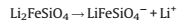
Due to the unique two-dimensional (2D) carbon crystal structure, graphene has been widely applied to be incorporated with the active materials for conversion devices and energy storage due to its high mechanical strength, light weight, remarkable thermal conductivity, large surface area and structural flexibility. In addition, recent progress has exhibited that the graphene-based nanomaterials could significantly affect optoelectronic and electronic devices, nanocomposites, chemical sensors, and energy storage [79, 80]. Learning from Hu and his co-workers, who presented grapheme-modified LiFePO4 that could help the electron transfer during cycling, reduce the irreversible capacity for the first cycle, and result in ~100% coulombic efficiency without any fading at different C-rates [18], Yang et al. presented a new 2D hybrid material consisted of LFS nanorods anchored on graphene and subsequently were bonded with highly conductive graphene nanosheets via a simple PVP modified method [32]. They found graphene could significantly promote the electrochemical performance of LFS, Fig. 4a shows the SEM and TEM images of the free LFS nanorods (LFSNRs). It reveals that the hydrothermal samples keep a 1D nanocrystal structure. The features both hydrothermal samples and nanorod (a length of 200-300 nm and diameter of 10-25 nm) are similar. Fig. 4b reveals the discharge capacity of about 130 mAh/g without obvious reduction at 2 A/g for more than 200 cycles, and the coulombic efficiency is nearly 100%. Thus, this new type of material has a sizable potential in commercial applications which have long operating lives and remarkable high energy, like electric vehicles. Fig. 4c shows that only one pair of redox peaks is observed at 3.2/2.5 V for the free LFSNRs, while several pairs of redox peaks are recorded for the LFSNR@graphene hybrid. Obviously, two reversible anodic peaks appear at about 4.3 and 4.7 V, 3.3 and 4.1 V indicate that the lithium storage in the cathode is increasing.

|
Download:
|
| Fig. 4. Characterization of the LFSNR@graphene hybrids: (a) SEM and transmission electron microscope (TEM) images of the free LFSNRs. (b) Cycle capacity at a high rate current density of 2 A/g for 240 cycles. (c) Cyclic voltammetry (CV) of the LFSNRs bonded with the graphene hybrid compared to the free LFSNR cathode. Reproduced with permission [32]. Copyright 2015, The Royal Society of Chemistry. | |
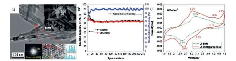
In recent years, 2D NSs, such as graphene, have received tremendous attention because of their fascinating chemical and physical characteristics and the thicknesses with miniscule atomic scale and extremely large surface area [81-88]. According to foregoing numerous experiments, we can learn that the stability of LFS cathode materials against volume and structural change [7]. Therefore, NSs based cathode materials is likely to improve the drawback of LFS, because of the abundant surface atoms and short lithium ion diffusion distance, which are directly connected with conducting material. LFSNSs were fabricated via a fast one-pot method with the supercritical fluid reaction utilizing aqueous ethanol as a solvent by Rangappa and his co-workers [6]. This composite can be synthesized in a three-step phenomenon, just as showing in Fig. 5e.

|
Download:
|
| Fig. 5. (a, b) TEM images of the as-prepared samples LFS. (c) Charge and discharge profile of first and second cycles, LFS measured at 45 ℃ temperatures at 0.02 C rate. (d) The cyclic performance of LFS samples. Schematic illustration of the LFS nanosheets formation under supercritical fluid conditions (e). Reproduced with permission [6]. Copyright 2012, American Chemical Society. | |
They demonstrated for the first time that 2D LFS electrodes showed a promoting two-lithium extraction/insertion performance in which the good cycle could reach to 15-20 cycles (Fig. 5d). The LFSNS phase endured a primary structural rearrangement to make phase maintained for first chargedischange cycles. Furthermore, the resultant phase offered high reversible capacity. Transmission electron microscopy images for the as-fabricated LFS sample are showed in Figs. 5a and b. It is obvious that the interlaced NSs produce a bunch of agglomerated NSs and that a handful of plat-like particles are also exhibited. As we all know that formed heterointerfaces of graphene-based composites have higher performance than the individual composites [89].
The three-dimensional (3D) graphene structure has itself particularity for LFS electrode material. Recently, novel 3D macroporous graphene-based LFS composites (3D G/LFS/C) have manufactured by Zhu and his co-workers [19, 90]. Fig. 6a shows the nanoscale LFS/C particles are anchored on the 3D graphene framework uniformly with macropores, which is useful for the electrolyte in the lithium-ion batteries to enter into the cathode. From Fig. 6b, we know that composite 3D G/LFS/C exhibits much better performances than both composites 2D G/LFS/C and LFS/C at all the high charge-discharge rates, owing to sufficient usage of the graphene nanosheets. Fig. 6c shows the typical charge-discharge curves at various high rates for 3D-G/LFS/C, which reveals that the samples' capacities are high for the LFS material at room temperature. So we can conclude that the 3D G/LFS/C reveals high electrochemical performances and excellent cycle performances.

|
Download:
|
| Fig. 6. (a) The SEM image of 3D-G/LFS/C shows that the nanoscale LFS/C particles are anchored on the 3D graphene framework uniformly, with nanoparticles both inside and outside of the macropores. (b) Specific capacitance variation at different current densities. (c) Show the typical charge-discharge curves at various high rates for 3D-G/LFS/C. Reproduced with permission [90]. Copyright 2014, American Chemical Society. | |
In addition, Zhang et al. prepared the 3D LFS/C based on a simple hydrothermal reaction, which accompanied a carbon nanopainting subsequently [91]. After LFS nanocrystallites (~60 nm) well painted with a uniform carbon network, this hierarchical 3D pores referred a more efficient infiltrate, transport and reserve of the electrolyte for cathodic mass transport. So carbon painting in the 3D LFS was in favor of lithium ion extraction/insertion capabilities.
As a result, we can point out that combining 3D with graphene and carbon nanopainting can further improve the electrochemical performance and optical transparency of LFS material than the LFS/ C composite [92].
2.4. Cation-dopingBased on previous researches, we know that cation-doping of alkali-, transition-, or inner transition-metal ions are efficient approachs to improve the electrochemical behaviors of lithium ion batteries cathode material [93-96]. Because doping metal cations in the lattice of LFS can enhance the diffusion ability of Li+ ions and ionic conductivity. In order to attach the widespread application of LFS, a large number of experiments have been engaged based on this aspect in recent years. For example, there are some literatures about the effects on the electrochemical property of LFS cathode after doping another single material, such as Mg, Ni, V, and so on. From these literatures, we can learn some obvious electrochemistry improvement of LFS (improving the conductivity and purity of the active LFS), though some disadvantages need overcoming (possibly change the structure and their theoretical capacities of initial LFS). Hereon, we will summarize some specific cationdoping of LFS in the following.
Zhang et al. successfully synthesized a series of Li2Fe1-xVxSiO4/C (x = 0.00, 0.03, 0.05 and 0.07) composites via a solid-state reaction, which accompanies refluxing-assisted [97]. They found that Vdoped LFS/C composites presented a better electrochemical performance than the pristine one: Delivering the highest initial discharge capacity of about 220 mAh/g, which likely due to Vdoped decreased charge transfer of LFS. Besides, by combining the result of density functional theory, we could conclude that Vdoping was a promising way to significantly enhance the electrochemical property of LFS cathode, though the loss of Fe content caused poor performance [98].
Furthermore, according to the way that substituting V for Fe/Si in LFS is an effective way to increase the available capacity, Toyama et al. set out to study the reaction voltage effect of V substitution for Si in LiFe0.5Mn0.5SiO4 materials [99]. Learning from Zhang et al. [97], Toyama and his co-workers throught the same way synthesized a series of V-substituted of LFS composites, and then analyzed the mechanism of discharge capacity change after Vdoping. The charge-discharge tests showed that Li2.2Fe0.4- Mn0.4Si0.8V0.2O2 exhibited a higher discharge capacity than Li2Fe0.5Mn0.5SiO2, which likely contributed by the charge and discharge voltage.
Zhang et al. successfully synthesized cobalt-doped (Co-doped) LFS/C composites via a refluxing-assisted solid-state reaction [100]. After LFS/C and Co-doped LFS/C composites were analyzed by the XRD patterns, they found that Co has been successfully doped into the lattice of LFS/C with a space group of P21, though there were some weak peaks represented Li2SiO3 and Fe2SiO4 impurities in the XRD pattern result. The electrochemical result showed that Co-doped in the LFS/C not only obviously exhibited a higher electrochemical capacity during the reversible lithium ion extraction/insertion, but also kept crystal structures of pristine LFS/C. According to the discharge capacity of 142.5 mAh/g at 3.0 C after Co-doped in the LFS/C and analyzing the reaction mechanism, they could conclude that cobalt-doping in LFS/C enhanced lithium ion diffusion coefficient and increased the defect concentration.
Basing on Mg-doping obviously improves the rate and cycle performances of LiFePO4 and Li3V2(PO4)3, Zhang and his coworkers via a sol-gel method synthesized Li2Fe0.97Mg0.03SiO4 at the same situation, besides adding magnesium acetate hydrated in synthesizing Li2Fe0.97Mg0.03SiO4 [101]. Both Mg-doped LFS and pristine LFS have a similar group P21 monoclinic structure. Comparing with these two kinds of lattice parameters, they could learn that Mg2+ has been successfully doped into crystal texture of LFS. To a certain degree, Li2Fe0.97Mg0.03SiO4 increased the reversible capacity and kept cycle stability of LFS for lithium ion batteries. However, their experimental results did not reach the expected level. So it was necessary to optimize synthetic method and further research about them.
Soon after, Qu et al. successfully fabricated Mg-doped LFS/C via Fe2O3 as Fe source and added Mg(CH3COO)2·4H2O for Mg-doped [73], which further studied electrochemical performance of Mgdoped LFS/C. The electrochemical performance result showed that Mg-doped LFS/C delivered a 190 mAh/g discharge capacity and kept a high charging process at 0.1C, even after 100 chargedischarge cycles. Therefore, we can conclude that it is possible to achieve the theoretical capacity of the cathode material after the substitution of Mg at the Fe site [62].
2.5. OthersIt is known to us, yttrium (Y) doping also proves to be effective to promote the electrochemical performance of cathode materials. Qiu et al. successfully prepared Y doped Li2Fe1-xYxSiO4/C composites via a sol-gel process, and investigated the effect of Y doping on the structure, morphology and electrochemical performance [102]. The materials show good cycle stability and high rate capability after moderate amount of Y doping.
There are some literatures identified the advantages and improvement of electrochemical performances after metal ion, another nonmetal element or substance doping from different aspects, too. For example, we can learn that the doping of Na, N, ascorbic acid, and LiFePO4 are viable for LFS [34, 103-105]. However, there are always some causes hampering the practical application of LFS. Therefore, more effective and straight forward methods are needed to be explored in the future.
3. Li2MnSiO4On the one hand, there is the relatively higher stability of Mn4+ than Fe4+ and Co4+ [38]. On the other hand, the Mn2+/Mn3+ and Mn3+/Mn4+ redox couples also deliver higher cell voltages than Fe2+/Fe3+, when lithium ions undergo the redox process [106, 107]; therefore, it is possible that Li2MnSiO4 (LMS) becomes the most promising cathode for lithium ion batteries in the orthosilicate family [108-110]. According to theoretical calculation, LMS could refer a capacity of 333 mAh/g after two lithium ions extracted [111]. However, just as LFS, LMS also suffers from a low structural instability and an awful cycle stability when testing electrochemical performances by CV, galvanostatic charge discharge and so on [112-117]. Furthermore, the crystal configuration of LMS will change obviously even after a few cycles. Hence, these issues have seriously limited the use of the LMS in practical applications. In another aspect, various strategies have been applied to overcome these challenges.
As we all known, the good electrochemical behaviors of the composites depend on excellent electronic conductivity [118]. Common strategies to deal with the problems include carbon coating, changing synthetic method, doping with another single metal ion, and reducing particle size [49]. In detail, carbon coating is effective way to increase electronic conductivity of the electrode materials. Changing synthetic method can change the lattice structure of electrode material, and then improving the electronic conductivity. Reducing particle size can shorten Li+ diffusion way. Modifying by metal ion can obviously enhance conductivity and structural stability [119].
3.1. Pure LMSThe presence of undesirable impurities in LMS electrode materials will affect their electrochemical performances, because the passivation layers of impurities on the surface of LMS may slow down Li-ion intercalation reaction between the active material and the electrolyte. Therefore, it is importance to control of phase purity in the synthesis of electrode materials with good properties. Although a number of LMS-related nanomaterials have been synthesized in recent years, it is also a big challenge to control the phase purity and morphology for this system. As we all known, the conventional solid-state approaches, which in a high temperature, would result in improving phase purity and crystallinity. However, it also increases the possibility of secondary reaction, leading to the collapse or aggregation of nanostructures. To achieve pure LMS, harsh conditions are usually required. In this connection, Yang group employed a wet-chemistry associated solid-state reaction strategy for the synthesis of LMS-related nanomaterials, while avoiding their disadvantages [60].
The high phase purity and high crystallinity of the LMS product were attained via a conventional solid-state reaction at high temperature, with a desirable porous nanobox microstructure. The voltage is one of the most important electrochemical parameters to evaluate the electrochemical performances of cathode materials for lithium batteries. The battery performance of LMS@C nanostructure as a cathode material was tested in a Li-ion halfcell within a cut-off voltage window of 1.5 V to 4.8 V. Due to the intrinsic poor ionic diffusivity of LMS, a low rate of 0.02 C (1 C = 333 mAh/g) was adopted for the galvanostatic cycling at 40 ℃. Fig. 7a shows that the sample has a greatly monodispersed cubic-like crystal structure (particle size about 120 nm). Fig. 7b and c reveal that the core-shell structure can be easily observed, owing to the contrast difference between the core and the shell. And the brief synthesis strategy (combine wet-chemistry with solid-state reaction) for phase-pure Li2MnSiO4@C porous nanoboxes are showed in Fig. 7d. What makes we excited is that this nanomaterial can achieve an initial charging capacity of 335 mAh/g.

|
Download:
|
| Fig. 7. (a) High-magnification TEM images of MnCO3 nanocubes. (b) HAADF-STEM images with linear EDX scanning profile of MnCO3@SiO2 core-shell nanocubes. (c) TEM images of LMS@C hollow nanomaterials. (d) Schematic illustration of the synthesis strategy for phase-pure LMS@C porous nanoboxes. Reproduced with permission [60], Copyright 2014, Elsevier Ltd. | |
3.2. LMS/carbon composites
Recently, due to electrochemical performance of carbonaceous material can be obviously improved [120-122], integrating nano-carbons into functional composites has become a popular research on account of potential application in energy field [19, 70, 123]. Besides, overcoming the insulating properties of silicate material and having a better understand the structure of LMS, even though numerous researchers have already studied this material, is important to improve nano-carbons for LMS electrochemical performance. From previous literatures, we know that LMS with carbon coasted show a high initial discharge capacity of 209 mAh/g, while the as-prepared LMS without carbon only deliver a very low discharge capacity [124, 72].
Recently, in order to create chemical or electrostatic interactions, it is widespread to use template-assisted for surface modification [125]. There is no doubt that the template refers an ordered and uniform atmosphere for their composite materials [126]. So we can assume that it is possible to synthetize LMS/C based on different templates, effectively controlling the aggregated distribution of composites.
The ordered mesoporous carbons CMK-3 and CMK-8 were as templates to prepare LMS by Kawase et al. [127]. The composite nanoparticles were successfully loaded into the mesoporous carbon templates by TEM observations. And then, in order to explore the contribution of CMK-3 and CMK-8, they used the templates which contained composite nanoparticles, for chargedischarge reaction of lithium ion batteries. The cyclic voltammetry result showed that the initial potential of LMS-CMK composites almost researched the theoretical capacity for the reaction with two Li+ ions per unit formula, 330 mAh/g. However, the capacity was instable, declining rapidly after a few cycles. Kawase et al. also found that another disadvantage of this template is that the LMSCMK composites were larger than LMS of particles size.
According to the research of Xie et al., they synthesized mesoporous LMS (M-LMS) via a template-assisted hydrothermal approach with in situ carbon coating technique [125]. In addition, a sample of bulk LMS (B-LMS), which used silica as template, was as a reference substance under the same conditions. XRD, SEM and N2 adsorption-desorption were used to characterize the physical properties of these cathode materials. The experimental results showed that M-LMS exhibited a high discharge capacity of 193 mAh/g at a constant current of 20 mA/g, while B-LMS just about 120.1 mAh/g. The pore sizes of porous structure ranged between 9-12 nm. The primary cause of electrochemical result owed to the porous structure referring a convenient approach for the electrolyte penetrating into the particles. And coating carbon was another significant cause, referring well electrical conductivity.
Furthermore, He et al. successfully fabricated LMS/C nanocomposite via a sacrificial hard-template and carbon source from water-soluble phenol-formaldehyde resin [128]. The nanoparticles size of sample is about 400 nm. Through SEM and TEM results showed that they were larger because of extra mesopores, the cathode of nanostructured LFS/C showed a high reversible discharge capacity of 200 mAh/g at C/10 (16 mA/g) rate at 1.5-4.8 V at 45 ℃.
As we all known, sol-gel synthesis is one of the most efficient ways to prepare nano-sized particles with high phase purity, and carbon coating is the commonly used way to increase electronic conductivity of the electrode materials. So combining with these two methods refers a potential chance to achieve the goal of well material cathode.
Dominko et al. via a modified Pechini sol-gel process fabricated LMS nanoparticles, and then carbon-coasted was using to modify in the final composite [29]. However, their researched result showed that the strategy has proven extremely efficient in the case of LiFePO4, which modified material nanoparticles with carboncoasted, did not be the same with LMS. The maximal capacity of prepared sample was about 140 mAh/g, and the cycling capacity lost about 4 mAh/g per cycle.
There are still other researchers to deal with this situation in recent years. It is reported that Liu and his co-workers via a glucose assisted sol-gel method with in situ carbon-coated synthesized LMS/C nanocomposites [129]. After all starting materials dissolving in the mixed solution, a uniform gel was made up. In order to gain the carbon-casted LMS composite, they calcined the dry gel at a high temperature of 650 ℃ for 6 h in running nitrogen atmosphere, subsequently. The electrochemical characterization showed a restively well property. The initial discharge capacity at 10 mA/g was 253.4 mAh/g. And at a scan rate of 50 mV/s, 97% capacitance still remained even after 2000 cycles.
It is undoubted that small and uniform particle size brings considerable benefit to the rapid and reversible lithium extraction/ insertion process [130]. In the view of this, temperature or hydrothermal method is beneficial to synthesis potential electrode materials for lithium ion batteries.
LMS/C cathode materials were fabricated under different calcination temperatures via a solution route by Wei and his coworkers [130]. After carbon-coasted, the nanoparticle size was larger than the others. And the increasing of calcination temperatures is probably another reason of the agglomeration of small particles. The test results showed that the addition of citric acid and ethylene glycol-las likely had an improvement to this situation. They synthesized LMS/C from 600 ℃ to 800 ℃, while the interval of 100 ℃ was determined. The electrochemical characterization show that 700 ℃ is the optimal temperature, while the initial discharge capacity reaches 187.12 mAh/g at 5 mA/g rate and about 100 mAh/g capacity retention at the 10th cycle.
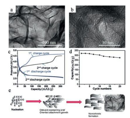
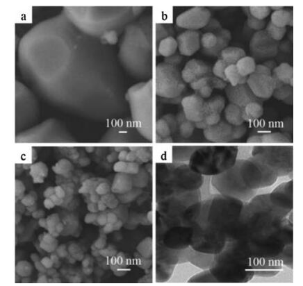
Molten salts as a reaction media provide a liquid reaction environment for reactants, thereby accelerating the reaction rate and providing a homogeneous structure of the final product. However, there are few researches about the synthesis of LFS via molten salt method so far. Wang and his co-workers studied about it, to a certain degree [130]. The LFS/C composites were prepared by a facile molten salt method followed by a carbon coating process. Submicron LMS particles are obtained in KCl-NaCl molten phase with a short reaction time of 3 h. And the specific morphology of samples is showed in Fig. 8. Figs. 8a-c reveal that the nanoparticles of samples were round and sizes range from small to large at the increasing the temperature gradient. Fig. 8d shows that a thin carbon layer about 10-25 nm is covered on the surface of LMS nanaopaticle. And the electrochemical results reveal that the smooth surface morphology and stable electrode/ electrolyte interfacial property are favorable for improving the reversible capacity and the cycle performance of LMS/C composites.

|
Download:
|
| Fig. 8. SEM images of Li2MnSiO4 and Li2MnSiO4/C (inset) prepared at 660 ℃ (a), 700 ℃ (b) and 750 ℃ (c). TEM image of the Li2MnSiO4/C composite (d). Reproduced with permission [131]. Copyright 2013, Elsevier Ltd. | |
Moreover, Gao et al. used an optimized step-sintering method to synthesis LFS/C nanoparticles: A stoichiometric precursor-based through a series of heat treatment process, which successively calcinated at 400 ℃ for 3 h, 500 ℃ for 2 h and 700 ℃ for 10 h. Finally, they obtained the samples of LMS/C.
Benefiting from smaller aggregates, higher-purity and better homogeneity, the better electrochemical performance of O-LMS is confirmed by the contrast charge-discharge experiments. The electrode material of this optimized-LFS could retain 73.5% of the initial discharge capacities ever after the 15th cycles. However, there is a disadvantage hindering the application of this method: The crystal structure of optimized-LFS is destructed fleetly.
3.3. Cation-doping LMSNi has been considered as a promising metal to moderate the structural distortion of LMS [132], which caused by the oxidation of Mn2+ to Mn4+ during delithiation process. For the Ni2+/Ni3+ couple the voltage is 4.5 V, while for the Ni3+/Ni4+ couple the voltage is 5.2 V. Therefore, Ni substitution is expected to enhance the average deinsertion voltage of LMS. Besides, the strategy that carboncoasted can improve the electrochemically active of the materials. However, the carbon coating process is under high temperature reducing conditions and heating in argon atmosphere, leading to the reduction of Ni2+ in the Li2Mn1-xNixSiO4 and Ni nanoparticles precipitation. Obviously, it is unfeasible to achieve a full capacity to Li2Mn1-xNixSiO4 electrode materials. Nonetheless, the electrochemical performance can be improved greatly after carboncoasted, comparing to the pristine LMS.
According to Saracibar et al. researches, for x = 0.2 had the best first charge capacities of 250 mAh/g for Li2Mn1-xNixSiO4 samples, comparing to for x = 0 and x = 0.1 [112]. However, they could not demonstrate the reason for the improvement of Li2Mn1-xNixSiO4. Besides, the average particle size of as-prepared sample is approximately 100 nm. For x = 0.2, certain larger plate-like particles can be distinguished due to the formation of spherical aggregates.
After Kokalj et al. via atomistic simulations mixing LMS with LFS can improve structural stability and high utilization of lithium. Basing on this, some research groups have go on further researching in recent years [133, 134]. Zhang and his colleagues reported that Li2Mn0.8Fe0.2SiO4/carbon composite nanofibers were successfully synthesized via iron doping and electrospinning [101]. The structure of the materials was optimized and the electronic/ ionic conductivity was enhanced. The SEM images of samples exhibit (Figs. 9a and b) that nanostructures of Li2Mn0.8Fe0.2SiO4/ carbon are relatively rough fibrous mats, and the diameter of nanofiber is smaller after heat treatment, comparing with the primary one. Fig. 9c reveals that only a few small areas of aggregation of primary particles can observed in fibers. Fig. 9d shows a different cycling performance compare of LMS powder, Li2Mn0.8Fe0.2SiO4 powder, and Li2Mn0.8Fe0.2SiO4/carbon nanofibers. It exhibits that Li2Mn0.8Fe0.2SiO4/carbon nanofibers reveal the slowest capacity fading during cycling (keep about 63.8% of capacity even after the 50th cycle), comparing to LMS and Li2Mn0.8Fe0.2SiO4 powders only about 20 and 40%, respectively. Finally, they concluded that Li2Mn0.8Fe0.2SiO4/carbon nanofiber cathodes showed an improved cycling performance and reversible capacity.

|
Download:
|
| Fig. 9. (a) SEM images of electrospun Li2Mn0.8Fe0.2SiO4/PAN nanofibers. (b) SEM images of Li2Mn0.8Fe0.2SiO4/carbon nanofibers obtained after heat treatment. (c) TEM images of Li2Mn0.8Fe0.2SiO4/carbon nanofibers with magnifications of (c) 10, 000x. (d) Cycling performance of Li2MnSiO4 powder, Li2Mn0.8Fe0.2SiO4 powder, and Li2Mn0.8Fe0.2SiO4/carbon nanofibers. Reproduced with permission [101]. Copyright 2012, Elsevier B.V. | |
In addition, Guo et al. demonstrated a synthesize method of Li2Fe1-xMnxSiO4/C through a wet process, mechanical activation and solid-state reaction under high temperature [135]. The effects of Li/Si molar ratio, Mn substitution, soaking time as well as roasting temperature on the structure and electrochemical performance of Li2Fe1-xMnxSiO4/C cathodes were all investigated. The optimally synthesized Li2Fe0.9Mn0.1SiO4/C has a capacity retention ratio of 94.3% and an initial discharge capacity of 158.1 mAh/g at C/32 between 1.5 V and 4.8 V after 30 cycles.
Besides, it is reported that Mg2+ can be intercalated to prepare magnesium manganese silicate electrochemical materials. The Mg2+ intercalation process can be improved by using nanoscopic particles, which is mainly ascribed to the lower interfacial charge transfer resistance as well as the shorter solid-state diffusion distance of Mg2+ [136]. Mg2+ can be intercalated into Li2Mg1.03Mn0.97SiO4, this material can act as electroactive species in advanced ion-transfer battery systems. And the SEM images of nanoparticle-samples synthesized at three different temperatures (a, 1000 ℃; b, 900 ℃; c, 800 ℃) were showed in Figs. 10a-c. It reveals that the particle size decreases with decreasing the temperatures (from 2 mm to 80 nm). And Fig. 10d further reveals that the particle distribution is narrow and particle size by TEM analysis.

|
Download:
|
| Fig. 10. SEM images of Mg1.03Mn0.97SiO4particles prepared at (a) 1000 ℃, (b) 900 ℃, and (c) 800 ℃. (d) TEM imaging of Mg1.03Mn0.97SiO4 particles. Reproduced with permission [136]. Copyright 2009, American Chemical Society. | |
Gummow et al. reported that Li2MgxMn1-xSiO4 (x = 0.4 or 0.5) were prepared via a solid-state process in argon atmosphere at 700 ℃ [137]. Then they characterized the samples' electrochemical performances by powder X-ray and neutron diffraction, SEM, and galvanostatic cell-cycling [138]. Compared to pristine LMS, Mg substituted LMS exhibited better stabilization of the P21/n form under lower temperatures. The P21/n structural form was able to be synthesized via solid state method under a calcination.
Zhang et al. reported Li2Mn(1-x)CrxSiO4/carbon composite nanofibers were successfully synthesized by electrospinning and Cr doping [139]. The electrospinning route promotes a conductive carbon nanofiber matrix to form, providing charge transfer and fast ion transport. The Cr doping can increase the volume of unit cell and induce defects in the lattice, so that the crystal structure stability is further improved. The as-prepared Li2Mn(1-x)CrxSiO4/ carbon composite nanofibers showed a good discharge capacity of 314 mAh/g after 5 cycles, as well as a great cycle stability. As the Cr doping ratio is equivalent to 0.06, the as-prepared Li2Mn0.94Cr0.06-SiO4 displayed optimal electrochemical property in terms of the enhanced cycle performance and improved capacity on account of the maximum unit cell volume.
3.4. OthersAs a family of mixed transition metal oxides, LiNi1/3Mn1/3Co1/3O2 plays an important role in improving electrochemical property of cathode materials for lithium ion batteries. Similar to that, the mixed transition metal silicates shows a great promise in vast areas, although the past results for Li2(Fe1-xMnx)SiO4 samples were unsatisfactory. Recently, the energy density theory calculations demonstrated the feasibility of multicomponent Li2Mn1/3Fe1/3 Ni1/3SiO4. First, the predicted extraction voltages are about 4.2 V for both the 1st and 2nd lithium ions. Second, compared with the single component systems, Li2Mn1/3Fe1/3Ni1/3SiO4 has a reduced band gap, resulting in better electronic conductivity. Nonetheless, whether it is feasible to synthesize the material and if the changes of structure influence the electrochemical property still remains to be seen [137].
Basing on the method that obtaining new metastable polymorphs by exchanging ions, Duncan et al. presented that Pn-LMS was first synthesized successfully by performing lithium ion exchange on Pn-Na2MnSiO4 [140]. Compared with Na2MnSiO4, the samples showed similar structures, which were assigned to the Pn space group. They found that both LMS polymorphs had an initial discharge capacity of 110 mAh/g and showed similar capacity fades. Although, Na2MnSiO4 delivers an initial capacity of 20 mAh/g, LiNaMnSiO4 possesses a stable capacity of 45 mAh/g, which increases to 60 mAh/g during cycling.
In addition, defect chemistry is thought to be an effective strategy for enhancing the electronic conductivity of the electrode materials, so that superb performance can be obtained. For example, the initial discharge capacity of Li1.9MnSiO4 reaches to 109.3 mAh/g while about 60 mAh/g is retained after 25 cycles. Besides, although the discharge capacity of the first two cycles for Li1.8MnSiO4 is a little low, it is gradually increasing to 110.9 mAh/g at the 4th cycle and (after 4 cycles) then keeps stable in the first 13 cycles. After an obvious capacity fading in the following several cycles, the electrode shows the capacity of 96.0 mAh/g.
4. Li2CoSiO4Many recent researches have focused on the synthesis methods, crystal structures, and electrochemical performances of LFS and LMS as cathode materials for lithium ion batteries. In principle, Li2CoSiO4 (LCS), as a potential high voltage positive electrode material of orthosilicates, can deliver a 325 mAh/g capacity [141]. However, there are few reports about practical application on LCS cathode materials [49], because it is difficult to synthetize nanosized LCS materials. The test results of LCS are unsatisfactory, especially the discharge performances, too. Herein, we will simply introduce the development of LCS in recent years following.
4.1. Pure LCSIn recent study, the analysis of structures of LCS provides a true understanding of the intrinsic structural evidence for the capacity fading of the LCS cathode materials. Samples of LCS have been synthesized investing lithium and cobalt nitrates, nanosized cristobalite and urea in the reaction via a combustion process. Then, the as-synthesized powders were followed by treating under at 950 ℃ for 48 h and quenched to room temperature subsequently [142]. They drew a conclusion that it was difficult to prepare novel high-pressure polymorphs of LCS. The result is not on account of the low compressibility of the LCS structures, but the strong cationic repulsion, the existence forms of which is denser. Hence, stabilizing LCS possessing a large cation/anion ratio in packings is more complicated than the tetrahedral one.
Yi research group reported the electrochemical properties of LCS materials, prepared by hydrothermal assisted sol-gel method in a precursor, and then in N2 atmosphere, 873 K sintering conditions for 10 h [117]. Chemical tests showed that LCS material had a 4.10 V lithium ion intercalation potential. The materials of carbon coating by mechanical ball milling, had a low specific capacity and poor reversibility: The first discharge capacity reached 93 mAh/g, just only 28.6% of theoretical capacity.
In addition, Truong and his co-workers reported that the LCS nanocrystals had been successfully prepared via a supercritical fluid route under 350 ℃ for 1 h and heating under 500 ℃ in air for 2 h subsequently [144]. On the basis of the atomic-scale image formation of polytype in LCS nanocrystals, the stacking sequence of variable unit cells in complicated structures can be known. The partial Li/Co atomic rearrangement in the LCS construction resulted in phase transformation as well as a stable stacking of polytype. What's more, atomic-resolution imaging gave evidence that the stacking of two different close-packed crystal structures in 3D space brought about the formation of polytype.
Later, LCS was prepared via sol-gel method which used polyacrylic acid (PAA) as the chelating agent for the first time by Savitha et al. [143]. The composition acts as a cathode material in lithium ion batteries. The preliminary test of the cell Li/0.2 mol/kg LCS cathode material showed that the first charge was approximately 204 mAh/g, while its discharge capacity was 32 mAh/g at 0.02 C rates under room temperature, respectively.
Moreover, Devaraju et al. demonstrated a simple and effective synthesis of LCS nanoparticles by the supercritical fluid process [141]. The structure of LCS has been investigated via annular bright field-scanning transmission electron microscopy and high angle annular dark field-scanning transmission electron microscopy analyses. It turned out that there was a tetrahedral arrangement of CoSiO4 in LCS structure. What is more, the material showed a remarkable electrochemical property. In detail, LCS delivered a discharge capacity of about 107 mAh/g at the initial chargedischarge cycles, showing a great promise in the application of battery. These results indicate a possible application as a cathode material in lithium ion batteries.
4.2. LCS/C compositesGong et al. reported that LCS was successfully synthesized via a solution-hydrothermal approach [145]. However, the sample was limited to 0.46 lithium per formula unit for the LCS/C composite materials, which possessing a reported charge capacity of 234 mAh/g, but its discharge capacity just 75 mAh/g.
In addition, He et al. reported that the concentration of [OH-] in the precursors (a highly ordered mesoporous carbon/silica framework) had great effects on the particle size and morphology of the LCS/C nanocomposites [49]. Nanospherical LCS/C particles, which had a uniform size between 300 nm and 400 nm, could be prepared via controlling the concentration of precursor and adjusting the system pH. Moreover, some of the nanospherical LCS/C particles showed an unusual hollow structure. Such size controlled LCS possessing homogeneous spherical morphology was reported for the first time, especially with the carbon incorporation. Compared with the one prepared from fumed SiO2, the nanocarbon inserted LCS/C cathodes showed splendid charge capacity performances. The first charge capacity of LCS/C sample is 162 mAh/g, while the reversible discharge capacity only ~33 mAh/g.
4.3. OthersLCS has been also identified to be a promising candidate as cathode material for lithium ion batteries. This material has the same structural characteristics as triphylite, delivering a high charge-discharge potential over 4.1 V [100]. Although improved cycling performance has been achieved, the high cost of synthesizing silicon nanostructures still hinders the industrial applications. Therefore, exploring alternative cathode materials with low cost and abundant sources is required.
Finally, we can conclude that although the LCS material has a high discharge potential platform and can obtain higher specific energy theoretically, its specific discharge capacity is low in most cases. In addition, the toxicity of cobalt is larger, the resource is limited and the price is high. Hence, all of these limit the commercial application of this material.
5. Conclusions and outlooksIn summary, this review has introduced various synthesis methods, nano-structures and electrochemical properties of Li2MSiO4 (where M = Mn, Fe, and Co) family, due to excellent development prospect of orthosilicates nanomaterials for lithium ion battery. Although there are kinds of compounds of orthosilicates, most of them need further study for their electrochemical properties for lithium ion batteries. For example, there are not a few articles about Li2NiSO4 for lithium ion batteries in recent years. However, its crystal is instable at room temperature. There are no relevant reports of obviously improvement synthesis about it so far, too. What's more, we also summarized kinds of different measures, such as nanostructures with ordered templates, carboncoasted, and cation-doping to deal with the drawbacks of orthosilicates in recent years. Although electrochemical properties of orthosilicates obtain obviously improvement in recent years, there are barely reports achieving a steady theoretical capacity of 320 mAh/g at present. To high oxidation voltage for the second lithium ion for M of Li2MSiO4 family, the interfacial side reactions are unavoidable. The passivation layer on orthosilicates cathode after carbon-coating and cation-doping will also significantly affect the electrochemical performances. Moreover, the instability of self-structure, low electrical conductivity and slow kinetics still seriously hinder scale application of Li2MSiO4 family for lithium ion batteries.
To realize commercialization of orthosilicates electrode materials in electrochemical energy storage devices, it needs more work to be done. In detail, future research should be focused on preparing the pure phase of the target product by optimizing the conditions and combining with different synthetic methods. Because undesired impurities' introduced in the samples will seriously influence their electrochemical performances. In addition, in-situ carbon coating, such as graphite and graphene, will improve orthosilicates electrode materials' cycle life, rate capability and capacity for lithium ion batteries, owing to the boundary resistance decrease of orthosilicates crystals. Moreover, cationdoping with another metal or material will enhance orthosilicates electrode materials' electrochemical performances and facilitate the diffusion of lithium ion batteries cathode material, because of increasing electrical conductivity and structural stability.
In another aspect, lithium metal silicates (such as, LCS and Li2NiSiO4) have been investigated as high-capacity anode materials in recent years [146-149]. So further reasearches of lithium metal silicates as anode materials for lithium ion batteries need to be done in the future.
AcknowledgementsThis work was supported by the Program for New Century Excellent Talents in University of China (No. NCET-13-0645) and the National Natural Science Foundation of China (Nos. NSFC-21201010, 21671170, 21673203), Innovation Scientists and Technicians Troop Construction Projects of Henan Province (No. 164200510018), Program for Innovative Research Team (in Science and Technology) in University of Henan Province (No. 14IRTSTHN004), Top-notch Academic Programs Project of Jiangsu Higher Education Institutions (No. PPZY2015B112), the Six Talent Plan (No. 2015-XCL-030), and Qinglan Project. We also acknowledge the Priority Academic Program Development of Jiangsu Higher Education Institutions and the technical support we received at the Testing Center of Yangzhou University.
| [1] |
B. Li, M.B. Zheng, H.G. Xue, H. Pang, Inorg. Chem. Front. 3(2016) 175-202. DOI:10.1039/C5QI00187K |
| [2] |
F. Zhang, L. Qi, Adv. Sci. 3(2016) 1-29. |
| [3] |
M. Hu, X.L. Pang, Z. Zhou, J. Power Sources 237(2013) 229-242. DOI:10.1016/j.jpowsour.2013.03.024 |
| [4] |
S.C.A. Majumdar, Nature 488(2012) 294-303. DOI:10.1038/nature11475 |
| [5] |
N. Choi, Z.H. Chen, S.A. Freunberger, et al., Angew. Chem. Int. Ed. 51(2012) 9994-10024. DOI:10.1002/anie.201201429 |
| [6] |
D. Rangappa, K.D. Murukanahally, T. Tomai, A. Unemoto, I. Honma, Nano Lett. 12(2012) 1146-1151. DOI:10.1021/nl202681b |
| [7] |
R. Dominko, D.E. Conte, D. Hanzel, M. Gaberscek, J. Jamnik, J. Power Sources 178(2008) 842-847. DOI:10.1016/j.jpowsour.2007.07.064 |
| [8] |
B.J. Landi, M.J. Ganter, C.D. Cress, R.A. DiLeo, R.P. Raffaelle, Energy Environ. Sci. 2(2009) 638-654. DOI:10.1039/b904116h |
| [9] |
B. Scrosati, J. Hassoun, Y.K. Sun, Energy Environ. Sci. 4(2011) 3287-3295. DOI:10.1039/c1ee01388b |
| [10] |
A. Manthiram, J. Phys. Chem. Lett. 2(2011) 176-184. DOI:10.1021/jz1015422 |
| [11] |
J. Zhang, P. Gu, J. Xu, H.G. Xue, H. Pang, Nanoscale 8(2016) 11689-11697. DOI:10.1039/C6NR02267G |
| [12] |
B.C. Melot, D.O. Scanlon, M. Reynaud, et al., ACS Appl. Mater. Interfaces 6(2014) 10832-10839. DOI:10.1021/am405579h |
| [13] |
M. Chen, W. Li, X. Shen, G.W. Diao, ACS Appl. Mater. Interfaces 6(2014) 4514-4523. DOI:10.1021/am500294m |
| [14] |
S. Goriparti, E. Miele, F.D. Angelis, et al., J. Power Sources 257(2014) 421-443. DOI:10.1016/j.jpowsour.2013.11.103 |
| [15] |
W.D. Li, B.H. Song, A. Manthiram, Chem. Soc. Rev. 10(2017) 3006-3059. |
| [16] |
H.F. Xiang, P.C. Shi, P. Bhattacharya, et al., J. Power Sources 318(2016) 170-177. DOI:10.1016/j.jpowsour.2016.04.017 |
| [17] |
R. Yi, J.T. Zai, F. Dai, M.L. Gordin, D.H. Wang, Nano Energy 6(2014) 211-218. DOI:10.1016/j.nanoen.2014.04.006 |
| [18] |
L.H. Hu, F.Y. Wu, C.T. Lin, A.N. Khlobystov, L. Jong, Nat. Commun. 4(2013) 1687. DOI:10.1038/ncomms2705 |
| [19] |
J.F. Ni, L. Zhang, S.D. Fu, et al., Carbon 92(2015) 15-25. DOI:10.1016/j.carbon.2015.02.047 |
| [20] |
A. Mancini, V.R. Barbieri, J.C. Neuefeind, K. Page, L. Malavasi, J. Mater. Chem. A 2(2014) 17867-17874. DOI:10.1039/C4TA04063E |
| [21] |
S.H. Yu, B. Quan, A. Jin, et al., ACS Appl. Mater. Interfaces 7(2015) 25725-25732. DOI:10.1021/acsami.5b07075 |
| [22] |
S. Furutsuki, S.C. Chung, S. Nishimura, et al., J. Phys. Chem. C 116(2012) 15259-15264. DOI:10.1021/jp304221z |
| [23] |
Z.P. Ding, Y.M. Feng, R. Ji, et al., J. Power Sources 349(2017) 18-26. DOI:10.1016/j.jpowsour.2017.03.023 |
| [24] |
M.S. Islam, C.A. Fisher, Chem. Soc. Rev. 43(2014) 185-204. DOI:10.1039/C3CS60199D |
| [25] |
M.E.A. Dompablo, M. Armand, J.M. Tarascon, U. Amador, Electrochem. Commun. 8(2006) 1292-1298. DOI:10.1016/j.elecom.2006.06.003 |
| [26] |
R. Dominko, M. Bele, M. Gaberscek, et al., Electrochem. Commun. 8(2006) 217-222. DOI:10.1016/j.elecom.2005.11.010 |
| [27] |
H.N. Girish, G.Q. Shao, RSC Adv. 5(2015) 98666-98686. DOI:10.1039/C5RA18594G |
| [28] |
C. Sirisopanaporn, R. Dominko, C. Masquelier, et al., J. Mater. Chem. 21(2011) 17823-17831. DOI:10.1039/c1jm12845k |
| [29] |
R. Dominko, M. Bele, A. Kokalj, M. Gaberscek, J. Jamnik, J. Power Sources 174(2007) 457-461. DOI:10.1016/j.jpowsour.2007.06.188 |
| [30] |
P. Ghosh, S. Mahanty, R.N. Basu, J. Electrochem. Soc. 156(2009) A677-A681. DOI:10.1149/1.3141517 |
| [31] |
S.S. Liu, L.J. Song, B.J. Yu, C.Y. Wang, M.W. Li, Electrochim. Acta 188(2016) 145-152. DOI:10.1016/j.electacta.2015.11.144 |
| [32] |
J.L. Yang, L. Hu, J.X. Zheng, et al., J. Mater. Chem. A 3(2015) 9601-9608. DOI:10.1039/C5TA01529D |
| [33] |
M.S. Islam, R. Dominko, C. Masquelier, et al., J. Mater. Chem. 21(2011) 9811-9818. DOI:10.1039/c1jm10312a |
| [34] |
H. Gao, Z. Hu, K. Zhang, F. Cheng, J. Chen, Chem. Commun. 49(2013) 3040-3042. DOI:10.1039/c3cc40565f |
| [35] |
N. Kuganathan, M.S. Islam, Chem. Mater. 21(2009) 5196-5202. DOI:10.1021/cm902163k |
| [36] |
M. Zhang, Q.P. Chen, Z.X. Xi, Y.G. Hou, Q.L. Chen, J. Mater. Sci. 47(2012) 2328-2332. DOI:10.1007/s10853-011-6048-9 |
| [37] |
A. Gutierrez, N.A. Benedek, A. Manthiram, Chem. Mater. 25(2013) 4010-4016. DOI:10.1021/cm401949n |
| [38] |
A. Liivat, J. Thomas, J.H. Guo, Y. Yang, Electrochim. Acta 223(2017) 109-114. DOI:10.1016/j.electacta.2016.12.008 |
| [39] |
C.X. Zhang, Z.L. Chen, Y.Z. Zeng, Z.F. Zhang, J. Li, Phys. Chem. C 118(2014) 7351-7356. DOI:10.1021/jp500905u |
| [40] |
D. Ensling, M. Stjerndahl, A. Nytén, T. Gustafsson, J.O. Thomas, J. Mater. Chem. 19(2009) 82-88. DOI:10.1039/B813099J |
| [41] |
S. Ferrari, M.C. Mozzati, M. Lantieri, Sci. Rep. 6(2016) 27896. DOI:10.1038/srep27896 |
| [42] |
A. Nytén, A. Abouimrane, M. Armand, T. Gustafsson, J.O. Thomas, Electrochem. Commun. 7(2005) 156-160. DOI:10.1016/j.elecom.2004.11.008 |
| [43] |
A. Nytén, S. Kamali, L. Häggström, T. Gustafsson, J.O. Thomas, J. Mater. Chem. 16(2006) 2266-2272. DOI:10.1039/B601184E |
| [44] |
G.H. Zhong, Y.Y. Li, P. Yan, et al., J. Phys. Chem. C 114(2010) 3693-3700. DOI:10.1021/jp910746k |
| [45] |
X.F. Du, H.L. Zhao, Y. Lu, et al., Electrochim. Acta 188(2016) 744-751. DOI:10.1016/j.electacta.2015.12.039 |
| [46] |
M. Oghbaei, F. Baniasadi, S. Asgari, J. Alloy. Compd. 672(2016) 93-97. DOI:10.1016/j.jallcom.2016.02.113 |
| [47] |
R. Dominko, J. Power Sources 184(2008) 462-468. DOI:10.1016/j.jpowsour.2008.02.089 |
| [48] |
D.L. Li, W. Zhang, R. Sun, et al., Nanoscale 8(2016) 12202-12214. DOI:10.1039/C5NR07783D |
| [49] |
G. He, G.M. Popov, L.D.F. Nazar, Chem. Mater. 25(2013) 1024-1031. DOI:10.1021/cm302823f |
| [50] |
W.C. Wang, H.C. Liang, L. Zhang, et al., Nano Res. 10(2017) 229-237. DOI:10.1007/s12274-016-1280-x |
| [51] |
C. Eames, A.R. Armstrong, P.G. Bruce, M.S. Islam, Chem. Mater. 24(2012) 2155-2161. DOI:10.1021/cm300749w |
| [52] |
M. Dompablo, R. Dominko, J. Amores, et al., Chem. Mater. 20(2008) 5574-5584. DOI:10.1021/cm801036k |
| [53] |
M. Avdeeva, Z. Mohamed, C.D. Ling, J. Solid State Chem. 216(2014) 42-48. DOI:10.1016/j.jssc.2014.04.028 |
| [54] |
J.L. Yang, J.X. Zheng, X.C. Kang, et al., Nano Energy 20(2016) 117-125. DOI:10.1016/j.nanoen.2015.12.004 |
| [55] |
T. Masese, Y. Orikasa, C. Tassel, et al., Chem. Mater. 26(2014) 1380-1384. DOI:10.1021/cm403134q |
| [56] |
C. Masquelier, L. Croguennec, Chem. Rev. 113(2013) 6552-6591. DOI:10.1021/cr3001862 |
| [57] |
C. Sirisopanaporn, A. Boulineau, D. Hanzel, et al., Inorg. Chem. 49(2010) 7446-7451. DOI:10.1021/ic100741x |
| [58] |
X. Lu, H.C. Chiu, Z. Arthur, et al., J. Power Sources 329(2016) 355-363. DOI:10.1016/j.jpowsour.2016.08.093 |
| [59] |
D. Jugovic, M. Milovic, V.N. Ivanovski, et al., J. Power Sources 265(2014) 75-80. DOI:10.1016/j.jpowsour.2014.04.121 |
| [60] |
X.F. Yang, J.H. Yang, K. Zaghib, M.L. Trudeau, J.Y. Ying, Nano Energy 12(2015) 305-313. DOI:10.1016/j.nanoen.2014.12.021 |
| [61] |
A. Saracibar, A.V.D. Ven, M.E.A. Dompablo, Chem. Mater. 24(2012) 495-503. DOI:10.1021/cm202818u |
| [62] |
T. Sarkar, M.D. Bharadwaj, U.V. Waghmare, P. Kumar, J. Phys. Chem. C 119(2015) 9125-9133. DOI:10.1021/acs.jpcc.5b01692 |
| [63] |
A. Boulineau, C. Sirisopanaporn, R. Dominko, et al., Dalton Trans. 39(2010) 6310-6316. DOI:10.1039/c002815k |
| [64] |
Y.H. Li, W.W. Sun, J. Liang, et al., J. Mater. Chem. A 4(2016) 17455-17463. DOI:10.1039/C6TA05313K |
| [65] |
C. Sirisopanaporn, C. Masquelier, P.G. Bruce, A.R. Armstrong, R. Dominko, J. Am. Chem. Soc. 133(2011) 1263-1265. DOI:10.1021/ja109695r |
| [66] |
A.R. Armstrong, N. Kuganathan, M.S. Islam, P.G. Bruce, J. Am. Chem. Soc. 133(2011) 13031-13035. DOI:10.1021/ja2018543 |
| [67] |
Z.L. Gong, Y.X. Li, G.N. He, J. Li, Y. Yang, Electrochem. Solid-State Lett. 11(2008) A60-A63. DOI:10.1149/1.2844287 |
| [68] |
Y.M. Xu, W. Shen, C. Wang, et al., Electrochim. Acta 167(2015) 340-347. DOI:10.1016/j.electacta.2015.03.170 |
| [69] |
S.V. Singh, S. Mitra, S. Singh, S. Mitra, Electrochim. Acta 123(2014) 378-386. DOI:10.1016/j.electacta.2014.01.045 |
| [70] |
C.L. Li, L. Gu, J. Tong, J. Maier, ACS Nano 5(2011) 2930-2938. DOI:10.1021/nn1035608 |
| [71] |
T. Masese, C. Tassel, Y. Orikasa, et al., J. Phys. Chem. C 119(2015) 10206-10211. DOI:10.1021/acs.jpcc.5b00362 |
| [72] |
T. Muraliganth, K.R. Stroukoff, A. Manthiram, Chem. Mater. 22(2010) 5754-5761. DOI:10.1021/cm102058n |
| [73] |
L. Qu, D. Luo, S.H. Fang, et al., J. Power Sources 307(2016) 69-76. DOI:10.1016/j.jpowsour.2015.12.137 |
| [74] |
L. Qu, Y. Liu, S.H. Fang, L. Yang, S. Hirano, Electrochim. Acta 163(2015) 123-131. DOI:10.1016/j.electacta.2015.02.102 |
| [75] |
S.J. Sun, C.M. Ghimbeu, Vix-Guterl C., et al., J. Power Sources 284(2015) 574-581. DOI:10.1016/j.jpowsour.2015.03.028 |
| [76] |
H. Zhu, X.Z. Wa, L. Zan, Y.X. Zhang, Electrochim. Acta 17(2014) 34-40. |
| [77] |
L.L. Zhang, S. Duan, X.L. Yang, et al., ACS Appl. Mater. Inter. 5(2013) 12304-12309. DOI:10.1021/am402434n |
| [78] |
T. Masese, C. Tassel, Y. Orikasa, et al., J. Phys. Chem. C 119(2015) 10206-10211. DOI:10.1021/acs.jpcc.5b00362 |
| [79] |
V. Singh, D. Joung, L. Zhai, et al., Prog. Mater. Sci. 56(2011) 1178-1271. DOI:10.1016/j.pmatsci.2011.03.003 |
| [80] |
Z.S. Wu, W. Ren, L. Xu, F. Li, H.M. Cheng, J. Am. Chem. Soc. 5(2011) 5463-5471. |
| [81] |
Y.L. Ding, Y. Wen, P.A.V. Aken, J. Maier, Y. Yu, Chem. Mater. 27(2015) 3143-3149. DOI:10.1021/acs.chemmater.5b00849 |
| [82] |
C.L. Tan, X.H. Cao, X.J. Wu, et al., Chem. Rev. 9(2017) 6225-6331. |
| [83] |
Y. Zhang, S.S. Yuan, Y.H. Zhao, H.G. Wang, C.D. He, J. Mater. Chem. A 2(2014) 7897-7903. DOI:10.1039/C4TA01057D |
| [84] |
J. Zhou, M. Chen, G.W. Diao, ACS Appl. Mater. Interfaces 5(2013) 828-836. DOI:10.1021/am302289v |
| [85] |
E.J. Yoo, J. Kim, E. Hosono, et al., Nano Lett. 8(2008) 2277-2282. DOI:10.1021/nl800957b |
| [86] |
X. Huang, Z.Y. Yin, S.X. Wu, et al., Small 7(2011) 1876-1902. DOI:10.1002/smll.201002009 |
| [87] |
Y.Q. Sun, Q. Wu, G.Q. Shi, Energy Environ. Sci. 4(2011) 1113-1132. DOI:10.1039/c0ee00683a |
| [88] |
Y.Q. Sun, G.Q. Shi, Polymer Phys. 51(2013) 231-253. DOI:10.1002/polb.23226 |
| [89] |
Q.L. Huang, W.X. Wei, Q.X. Yan, C. Wu, X. Zhu, Mater. Lett. 152(2015) 203-206. DOI:10.1016/j.matlet.2015.03.117 |
| [90] |
H. Zhu, X.Z. Wu, L. Zan, Y.X. Zhang, ACS Appl. Mater. Inter. 6(2014) 11724-11733. DOI:10.1021/am502408m |
| [91] |
L. Zhang, J.F. Ni, W.C. Wang, J. Guo, L. Li, J. Mater. Chem. A 3(2015) 11782-11786. DOI:10.1039/C5TA02433A |
| [92] |
R.A. Nistor, D.M. Newns, G.J. Martyna, ACS Nano 5(2011) 3096-3103. DOI:10.1021/nn200225f |
| [93] |
L.M. Li, H.J. Guo, X.H. Li, et al., J. Power Sources 189(2009) 45-50. DOI:10.1016/j.jpowsour.2008.12.017 |
| [94] |
Z. Shi, P.F. Ndione, L.Y. Lim, et al., Chem. Mater. 26(2014) 1867-1873. DOI:10.1021/cm404031k |
| [95] |
L.L. Yi, X.Y. Wang, G. Wang, et al., Electrochim. Acta 222(2016) 1354-1364. DOI:10.1016/j.electacta.2016.11.111 |
| [96] |
L. Zhu, L. Li, T.M. Cheng, D.S. Xu, J. Mater. Chem. A 3(2015) 5449-5456. DOI:10.1039/C5TA00230C |
| [97] |
L.L. Zhang, H.B. Sun, X.L. Yang, et al., Electrochim. Acta 152(2015) 496-504. DOI:10.1016/j.electacta.2014.11.172 |
| [98] |
H. Hao, J.B. Wang, J.L. Liu, T. Huang, A.S. Yu, J. Power Sources 210(2012) 397-401. DOI:10.1016/j.jpowsour.2011.11.066 |
| [99] |
T. Toyama, S. Takahashi, T. Toyama, J. Power Sources 294(2015) 312-316. DOI:10.1016/j.jpowsour.2015.06.029 |
| [100] |
L.L. Zhang, S. Duan, X.L. Yang, et al., J. Power Sources 274(2015) 194-202. DOI:10.1016/j.jpowsour.2014.10.048 |
| [101] |
S. Zhang, Y. Li, G.J. Xu, et al., J. Power Sources 213(2012) 10-15. DOI:10.1016/j.jpowsour.2012.04.011 |
| [102] |
H.L. Qiu, H.J. Yue, T. Zhang, et al., Electrochim. Acta 188(2016) 636-644. DOI:10.1016/j.electacta.2015.12.042 |
| [103] |
Y. Ren, P. Lu, X.B. Huang, et al., Mater. Lett. 173(2016) 207-210. DOI:10.1016/j.matlet.2016.03.048 |
| [104] |
M. Armanda, M.E.A. Dompablo, J. Mater. Chem. 21(2011) 10026-10034. DOI:10.1039/c0jm04216a |
| [105] |
M. Li, L.L. Zhang, X.L. Yang, et al., J. Solid State Electrochem. 19(2015) 415-421. DOI:10.1007/s10008-014-2603-z |
| [106] |
S. Devaraj, M. Kuezma, C.T. Ng, P. Balaya, Electrochim. Acta 102(2013) 290-298. DOI:10.1016/j.electacta.2013.04.009 |
| [107] |
N.P. Wagner, P.E. Vullum, M.K. Nord, A.M. Svensson, F.V. Bruer, J. Phys. Chem. C 120(2016) 11359-11371. DOI:10.1021/acs.jpcc.6b01831 |
| [108] |
Y. Pei, Q. Chen, C.Y. Xu, et al., J. Mater. Chem. A 4(2016) 9447-9454. DOI:10.1039/C6TA01269H |
| [109] |
C. Hwang, T. Kim, Y. Noh, et al., Mater. Lett. 164(2016) 270-273. DOI:10.1016/j.matlet.2015.10.113 |
| [110] |
Q.H. Cheng, W. He, X.D. Zhang, M. Li, L.Z. Wang, J. Mater. Chem. A 22(2017) 10772-10797. |
| [111] |
V. Ramar, P. Balaya, J. Power Sources 306(2016) 552-558. DOI:10.1016/j.jpowsour.2015.12.033 |
| [112] |
A. Saracibar, Z. Wang, K.J. Carroll, et al., J. Mater. Chem. A 3(2015) 6004-6011. DOI:10.1039/C4TA03367A |
| [113] |
Z. Gong, Y. Yang, Energy Environ. Sci. 4(2011) 3223-3242. DOI:10.1039/c0ee00713g |
| [114] |
S.Y. Chung, J.T. Bloking, Y.M. Chiang, Nat. Mater. 1(2002) 123-128. DOI:10.1038/nmat732 |
| [115] |
G.K.P. Dathar, D. Sheppard, K.J. Stevenson, Chem. Mater. 23(2011) 4032-4037. DOI:10.1021/cm201604g |
| [116] |
H. Lee, S.D. Park, J. Moon, et al., Chem. Mater. 26(2014) 3896-3899. DOI:10.1021/cm500803e |
| [117] |
M. Kuezma, S. Devaraj, P. Balaya, J. Mater. Chem. 22(2012) 21279-21284. DOI:10.1039/c2jm34455f |
| [118] |
Y.X. Li, Z.L. Gong, Y. Yang, J. Power Sources 174(2007) 528-532. DOI:10.1016/j.jpowsour.2007.06.126 |
| [119] |
K. Zhang, X.P. Han, Z. Hu, et al., Chem. Soc. Rev. 44(2015) 699-728. DOI:10.1039/C4CS00218K |
| [120] |
Y.P. Wu, E.R. Holze, J. Power Sources 114(2008) 228-236. |
| [121] |
H.Q. Li, H.S. Zhou, Chem. Commun. 48(2012) 1201-1217. DOI:10.1039/C1CC14764A |
| [122] |
I. Belharouak, A. Abouimrane, K. Amine, J. Phys. Chem. C 113(2009) 20733-20737. DOI:10.1021/jp905611s |
| [123] |
M.S. Tos1awski, M. Molenda, K. Furczon, R. Dziembaj, J. Power Sources 244(2013) 510-514. DOI:10.1016/j.jpowsour.2013.02.078 |
| [124] |
H. Wang, T.L. Hou, D. Sun, et al., J. Power Sources 247(2014) 497-502. DOI:10.1016/j.jpowsour.2013.08.115 |
| [125] |
M. Xie, R. Luo, R.J. Chen, et al., ACS Appl. Mater. Interfaces 7(2015) 10779-10784. DOI:10.1021/acsami.5b01061 |
| [126] |
H. Nishihara, T. Kyotani, Adv. Mater. 24(2012) 4473-4498. DOI:10.1002/adma.v24.33 |
| [127] |
T.K.S. Kawase, H. Yoshitake, Micropor. Mesopor. Mater. 155(2012) 99-105. DOI:10.1016/j.micromeso.2012.01.021 |
| [128] |
G. He, A. Manthiram, Adv. Funct. Mater. 24(2014) 5277-5283. DOI:10.1002/adfm.v24.33 |
| [129] |
S.K. Liu, J. Xu, D.Z. Li, et al., J. Power Sources 232(2013) 258-263. DOI:10.1016/j.jpowsour.2012.12.126 |
| [130] |
W. Yi, L.J. Wang, J. Yun, et al., Acta Phys. Chim. Sin. 27(2011) 2587-2592. |
| [131] |
W. Fei, Y.M. Wang, D.M. Sun, et al., Electrochim. Acta 119(2014) 131-137. DOI:10.1016/j.electacta.2013.12.057 |
| [132] |
H. Deng, S.X. Zhao, X. Wu, et al., RSC Adv. 6(2016) 111539-111548. DOI:10.1039/C6RA22357E |
| [133] |
A. Kokalj, R. Dominko, G. Mali, et al., Chem. Mater. 19(2007) 3633-3640. DOI:10.1021/cm063011l |
| [134] |
X.L. Jiang, H.Y. Xu, J. Liu, et al., Nano Energy 7(2014) 1-9. DOI:10.1016/j.nanoen.2014.04.005 |
| [135] |
H.J. Guo, X. Cao, X.Q. Li, et al., Electrochim. Acta 55(2010) 8036-8042. DOI:10.1016/j.electacta.2010.03.001 |
| [136] |
Y. Li, J. Yang, J.L. Wang, Y. Li, J. Phys. Chem. C 113(2009) 12594-12597. DOI:10.1021/jp903188b |
| [137] |
J. Gummow, Y. He, J. Power Sources 253(2014) 315-331. DOI:10.1016/j.jpowsour.2013.11.082 |
| [138] |
R.J. Gummowa, N. Sharma, V.K. Peterson, Y. He, J. Power Sources 197(2012) 231-237. DOI:10.1016/j.jpowsour.2011.09.013 |
| [139] |
S. Zhang, Z. Lin, L. Ji, et al., J. Mater. Chem. 22(2012) 14661-14666. DOI:10.1039/c2jm32213g |
| [140] |
H. Duncan, A. Kondamreddy, P.H.J. Mercier, et al., Chem. Mater. 23(2011) 5446-5456. DOI:10.1021/cm202793j |
| [141] |
M.K. Devaraju, Q.D. Truong, I. Honma, RSC Adv. 3(2013) 20633-20638. DOI:10.1039/c3ra42540a |
| [142] |
D.S. Pérez, U. Amador, J. Tortajada, R. Dominko, M. Dompablo, Inorg. Chem. 51(2012) 5779-5786. DOI:10.1021/ic300320r |
| [143] |
S. Thayumanasundaram, V.S. Rangasamy, J.W. Seo, J.P. Locquet, Ionics 20(2014) 935-941. DOI:10.1007/s11581-013-1057-0 |
| [144] |
Q.D. Truong, M.K. Devaraju, Y. Sasaki, H. Hyodo, I. Honma, Chem. Eur. J. 20(2014) 16210-16215. DOI:10.1002/chem.v20.49 |
| [145] |
Z.L. Gong, Y.X. Li, Y. Yang, J. Power Sources 174(2007) 524-527. DOI:10.1016/j.jpowsour.2007.06.250 |
| [146] |
X.J. Wei, C.J. Tang, X.P. Wang, et al., ACS Appl. Mater. Interfaces 7(2015) 26572-26578. DOI:10.1021/acsami.5b07863 |
| [147] |
C.J. Tang, J.X. Zhu, X.J. Wei, et al., Energy Storage Mater. 7(2017) 152-156. DOI:10.1016/j.ensm.2017.01.008 |
| [148] |
J.X. Zhu, C.J. Tang, Z.C. Zhuang, et al., ACS Appl. Mater. Interfaces 9(2017) 24584-24590. DOI:10.1021/acsami.7b06088 |
| [149] |
C.J. Tang, J.Z. Sheng, C. Xu, et al., J. Mater. Chem. A 3(2015) 19427-19432. DOI:10.1039/C5TA04680G |