 2017, Vol. 28


b State Key Laboratory of Fluid Power and Mechatronic Systems, Zhejiang University, Hangzhou 310027, China;
c Institute of Process Equipment, College of Energy Engineering, Zhejiang University, Hangzhou 310027, China
With the rapid depletion of fossil fuels and the increasing environmental concerns, such as the global warming and the air pollution, a lot of efforts have been dedicated to develop new green energy, such as wind energy and solar energy [1, 2]. However, storage and transportation of energy now become emerging challenges. The recent developments of electric vehicles also demand high-energy-density storage systems [3]. In order to meet the growing requests, large-scale battery systems are required to have high energy density, long life cycle and low cost [4, 5]. Though lithium ion battery has achieved tremendous success in last two decades, its low energy density now becomes the key bottleneck to meet the ever-growing demands of new technologies ranging from electric vehicles to grid-scale energy storages [6-9]. Rechargeable lithium metal battery, showing the advantages of extremely high theoretical specific capacity (3860 mAh/g), low gravimetric density (0.59 g/cm3) and lowest negative redox potential (-3.04 V vs. standard hydrogen electrode), has been extensively investigated as the next generation high energy storage system and opens up the opportunities for high-energy un-lithiated cathode materials such as sulphur and oxygen, among others [10].
Lithium metal is considered as the holy grail of energy storage system due to its unique properties [10, 11]. The use of lithium metal in battery has been explored for decades [12, 13]. The lithium metal can be paired with sulfur cathode for lithium-sulfur batteries with very high energy density [14-17]. When solid electrolyte is introduced between routine oxide cathode, all solid state battery with lithium metal anode is also expected with very high energy density [18, 19]. However, the practical application of lithium metal battery is limited by its inhomogeneous lithium deposition and subsequent dendrite growth, which results in unreliable performances and safety issues. Because metallic lithium has a high Fermi energy level, the lithium anode continually consumes liquid electrolytes to form a solid electrolyte interphase (SEI) film on the surface [20, 21]. During the charging and discharging cycles, lithium deposits and dissolves at the electrode and its inhomogeneous deposition behavior causes the formation of lithium dendrites and dead lithium fractions, resulting in decreased Coulombic efficiencies [22, 23]. Ultimately, the growth of lithium dendrites can bridge the interelectrode gap and short the circuit of the battery, causing overheating or even thermal runaway [24, 25]. Controlling the lithium deposition and inhibiting its dendritic growth are thus indispensable to capitalize the benefits of lithium metal battery for commercial applications.
Intensive efforts have been made to address the problems of lithium metal batteries. Numerous experiments and theoretical simulations have been carried out to understand the failure mechanism of lithium metal anode and to improve the performance of lithium metal batteries. The nucleation and growth of lithium dendrites are considered to be the main factor, causing the failure of a cell. An analytical frameworks had been developed to study the early stages of the nucleation and growth of lithium metal during heterogeneous electrodeposition of reaction rate limited systems [26]. Five regimes, i.e., the nucleation suppression regime, the long incubation time regime, the short incubation time regime, the early growth regime, and the late growth regime, were clearly identified to illustrate the complex heterogeneous nucleation behavior. The stability of deposition at the lithium anode had also been investigated, which was determined by five parameters, i.e., the current density (J), the surface tension of lithium anode in the electrolytes (S), the transference number of lithium ion (tLi), the ionic conductivity (σ) and the shear modulus of the separator (G) [12]. To address the problem of lithium dendrites, a polymer electrolyte with a rigid-flexible structure for solid-state lithium metal batteries had been proposed [27]. The interpenetrating network of poly(ether-acrylate) electrolyte formed on the lithium surface suppressed the growth of lithium dendrites during the battery cycling and enhanced the transportation of lithium ion for high-rate operation of the battery. Fluoroethylene carbonate was also used to assist the uniform deposition of lithium [28]. The additive is benefited to obtain a compact and stable LiF-rich SEI film, which is beneficial to achieve a uniform plating of metallic lithium and a significantly high Coulombic efficiency.
Nowadays, the main approaches to suppress the growth of lithium dendrites could be categorized into the following four aspects. (1) Developing functional electrolytes or adding additives in the electrolytes to form a compact and stable SEI layer at the surface of the lithium anode [29-36]. Metallic lithium is thermodynamically active and will react with the electrolyte to form a SEI layer on the surface, which protects lithium from the electrolyte and assists the uniform deposition of lithium. However, most SEI layers are fragile and they break easily during the plating and stripping process of lithium. Their breaking sites are generally the nucleation and growth sites of lithium dendrites. Developing a compact and stable SEI layer using functional electrolytes or additives are promising to suppress the growth of lithium dendrites. However, the electrochemical/chemical reaction in the battery is very complicated and the SEI layer, which consists of complex reduction products of the electrolyte and degradation products of the lithium salt, is not fully understood yet. (2) Introducing a solid state electrolyte [37-43]. Solid state electrolytes could suppress the unfavorable side reactions with lithium metal and have a high mechanical modulus to hinder the growth of lithium dendrites. However, the low ionic conductivity and the large interfacial impedance between the solid state electrolyte and the electrode need to be improved substantially. (3) Using a mechanically strong separator to physically prevent the penetration of lithium dendrites [44-48]. Though it could prevent the lithium dendrites short-circuit the cell, the separator can not suppress the formation of lithium dendrites and dead lithium fractions during the cycling, which will persistently decrease the Coulombic efficiency. (4) Constructing a functional hybrid electrode [49-53], such as modifying the current collector with some nanostructure, which lowers the local current density and homogenizes the distribution of the lithium ion flux, prelithiating the 3D host matrix with molten lithium, which alleviates the huge volume change of lithium metal during cycling and improves the nucleation behavior of lithium, and adding a protective layer, which assists the deposition of lithium and suppresses the growth of lithium dendrites. Recent studies of lithium metal batteries in this area have shown promising results and it has become the most rigorous area.
In this review, we focus on the design of lithium electrode and its recent advancements, which suppress the growth of lithium dendrites and improve the performance of the rechargeable batteries. To suppress the growth of lithium dendrites, the general design rules of the system require a uniform lithium ion flux, a low current density, a homogeneous nucleation process and a stable SEI layer. Improvements of the battery performance have been achieved through the delicate design of lithium electrode and here they are summarized into three groups: ⅰ) optimizing the 3D porous nanostructure of current collector, ⅱ) constructing rational host for lithium metal and prelithiating the 3D host matrix through the molten lithium infusion, ⅲ) protecting the surface of lithium metal by functional layers. An outlook of the challenges and the potentials of lithium metal battery is also provided, which will facilitate the future development of lithium metal battery.
2. Advanced current collector 2.1. Planar current collector versus 3D porous current collectorThe current collector, a key component of the electrode, significantly influences the initial nucleation and subsequent growth of lithium metal deposits. In a battery with planar current collector, if the surface is perfectly smooth, a uniform electric field over the entire electrode surface is expected, which drives a uniform lithium ion flux to the anode and thus a homogeneous deposition of lithium metal. However, the planar current collector is generally not perfect. Both the strength of electric field lines and preferential transportation of lithium ions to the rough regions on the surface render spatially inhomogeneous plating of lithium metal, which is the original formation of lithium nuclei. Once the nuclei are large enough, it will grow faster than others and form a protuberance on the flat surface. More charge will accumulate at the tip of the lithium protuberance, the high charge density in turn results in a stronger electric field near the tip and thus a larger lithium ion flux, which further speeds up the growth of lithium dendrites. Different from conventional planar electrode, lithium metal electrode with rationally designed structure is able to homogenize the electric field and the lithium ion flux over a large area. Therefore, advanced electrodes with various 3D frameworks have been developed to improve the deposition behavior of lithium metal and suppress the growth of lithium dendrites, which have significantly benefited the developments of lithium metal battery.
To ensure a relatively even deposition of lithium metal under a relatively uniform electric field and resist the growth of lithium dendrites, a submicron 3D skeleton on the copper current collector was introduced to improve the deposition behavior of metallic lithium [54]. Numerous protuberant tips are designed on the submicron fibers, which serve as the charge centers to obtain a globally uniform electric field. Therefore, metallic lithium prefers to nucleate and grow on the copper skeleton, eventually filling the 3D framework and forming a relatively stable and flat lithium surface (Figs. 1a and b). The lithium metal batteries using these electrodes can run for 600 h without any short-circuit. A simple dealloying process was also used to produce a 3D interconnected framework in the copper current collector (Figs. 1c and d) [55]. The lithium metal battery with such a 3D porous current collector shows reduced polarization, high Coulombic efficiency (>97% after 250 cycles) and long lifespan (up to 1000 h). As compared to a planar copper foil (Fig. 1e), a free-standing copper nanowire network (Fig. 1f) or a porous copper mesh (Fig. 1g) could promote a more uniform lithium ion flux [56, 57]. Simulations suggest that lithium preferentially deposits within the microchannels of a porous copper current collector and an array of vertically aligned microchannels leads to a macroscopically uniform lithium ion flux (Fig. 1 h) [58].

|
Download:
|
| Fig. 1. Suppression of lithium dendrites by uniform lithium ion flux and lower current density. Schematic illustration of electrochemical deposition of lithium metal on a planar current collector (a, c, e) and on a 3D porous current collector (b, d, f, g). The deposition of lithium on traditional planar current collector is susceptible to inhomogeneous nucleation and growth, which eventually causes the lithium dendrites. In 3D current collector with porous framework, the electric field is more uniform and lithium ion flux is more homogeneous, resulting in a relatively even lithium deposition. (h) Schematic diagram of porous copper current collector and the simulation results of the distribution of the current density within the channels. The scale bars in the image are 10 μm. Figures a and b adapted with permission [54]. Copyright 2015, Nature Publishing Group; Figures c and d adapted with permission [55]. Copyright 2016, Wiley-VCH; Figures e and f adapted with permission [56]. Copyright 2016, American Chemical Society. Figure g adapted with permission [57] Copyright 2017, Wiley-VCH. Figure h adapted with permission [58]. Copyright 2017, Wiley-VCH. | |
The application of other 3D current collectors, including porous graphite [59], reduced graphene oxide [60], carbon nanotubes [61], 3D porous graphene [62], graphitized carbon fibers [63], have been explored recently. The pore volume, pore size, and surface area are important parameters of the 3D porous current collectors, which influence the deposition behavior of lithium metal [64, 65]. To achieve a homogeneous lithium ion flux and a uniform lithium metal deposition, the 3D porous framework needs to be carefully designed and the pores of the current collectors are preferentially to be small and monodisperse. Pores (macroscopic scale), such as those in commercial copper foam, are too large to be effective and these current collectors behave more like the conventional planar current collector. The experiments show that lithium dendrites nucleate and grow on the copper foam and metallic lithium detaches easily from the backbones of the copper framework during the cycling, resulting in dead lithium [55]. With the unique surface, pore, and 3D connecting structures of different nanomaterials, lithium plating/stripping processes have been regulated.
2.2. Deposition of lithium guided by nucleation seedsLithium is expected to deposit uniformly on an ideal planar electrode, as there are no preferred nucleation sites. However, some rough regions on the surface could produce local high strength of electric field and large flux of lithium ions, leading to the formation of large lithium nuclei. These large lithium nuclei are rare on a planar current collector, but they generally grow fasts, leading to the formation of lithium dendrites. However, once the lithium nucleuses are large enough, their growth will dominate, leading to the formation of lithium dendrites. The 3D porous current collectors discussed above ensure a uniform deposition of lithium by homogenizing the electric field and the lithium ion flux. The protuberant tips on the submicron fibers also provide numerous nucleation sites, assisting the homogenous deposition of metal. Instead of structural heterogeneity, such as the protuberances, chemically modified regions, which have a strong binding energy with lithium atoms, could also serve as nucleation sites. Generally, a lithiophilic surface is preferred for stable lithium metal nucleation and subsequently deposition of metallic lithium. Therefore, the nucleation process of lithium metal could be controlled by tailoring the interaction between lithium and the substrate, e.g., designing a current collector with patterned lithiophilic surface, which significantly enhances the uniform deposition behavior of metallic lithium.
The nitrogen-doped graphene with dense and uniform lithiophilic functional groups was designed as a current collector to regulate the nucleation and suppress the growth of lithium dendrites, as shown in Figs. 2a and b [66]. Calculations by density functional theory suggest pyrrolic nitrogen and pyridinic nitrogen exhibit larger binding energies of -4.46 eV and -4.26 eV with lithium atom than copper of -2.57 eV. The result of the calculations indicates that there is a strong interaction between lithium atom and the nitrogen-doped graphene, while the copper has a much weaker interaction with lithium atom. A stronger binding energy of lithium atoms leads to a better adsorption of lithium and a smaller nucleation overpotential. Therefore, lithium prefers to adsorb and nucleate on these lithiophilic functional groups. Compared to a traditional current collector, the nitrogendoped graphene offers dense nucleation sites uniformly distributed on the surface, resulting in uniform and smooth lithium deposition.

|
Download:
|
| Fig. 2. Suppression of lithium dendrites by controlling the nucleation and growth process. Schematic illustration of the process of lithium nucleation and plating on N-doped graphene electrode current collector (a) and copper foil electrode (b). Due to the higher affinity of lithium on the N-doped graphene electrode affinity of lithium on the N-doped graphene electrod current collector, lithium nucleates and grows more homogeneously on the surface. Reproduced with permission [66]. Copyright 2017, Wiley-VCH. Lithium dendrites could still form during the cycling, when lithium deposits on the surface of hierarchical porous carbon scaffold (c), and lithium dendrites are suppressed when confining the nucleation and growth of lithium within the pores using ZnO nanoparticles as the seeds (d). Reproduced with permission [67]. Copyright 2017, Elsevier. | |
A 3D hierarchical current collector decorated with ZnO quantum dots was also demonstrated [67]. The ZnO quantum dots serve as the lithiophilic functional groups and confine the nucleation and growth of lithium metal within the structure, as shown in Figs. 2c and d. During the initial period of lithium deposition, lithium ions prefer to react with ZnO quantum dots via Li+ + ZnO→Li2O + Zn, and deposited lithium will subsequently alloy with zinc to form LiZn, which is highly conductive and lithiophilic. Therefore, the ZnO quantum dots are able to serve as nucleation sites of lithium metal and the uniform distribution of ZnO quantum dots then guide the uniform deposition of lithium within the structure, suppressing the formation of lithium dendrites. Similarly, using ultrafine silver nanoparticles as the nucleation seeds to direct the deposition of lithium uniformly on the 3D framework is reported, as shown in Fig. 3a [68]. Systematical investigation of the nucleation overpotential of lithium on various materials was carried out and suggested that an appreciable nucleation barrier exists for metals with negligible solubility in lithium (such as Cu), while no nucleation barrier is present for metals exhibiting a definite Li solubility (such as Au, Ag and Zn) [69]. Therefore, Au seeds embedded in hollow carbon nanocapsules are also able to guide the deposition of lithium metal within the carbon nanocapsules (Fig. 3b), and the battery shows high Coulombic efficiency (over 98%) for over 300 cycles in an alkyl carbonate electrolyte.

|
Download:
|
| Fig. 3. Seed-guided nucleation and growth of lithium on the electrode. (a) Uniform deposition of lithium on a 3D network of carbon nanofilaments decorated with silver nanoparticles, and nonuniform lithium deposition on bare carbon nanofilaments. Reproduced with permission [68]. Copyright 2017, Wiley-VCH. (b) Fabrication of hollow carbon nanocapsules decorated with gold nanoparticles and the confinement of lithium nucleation and growth within the carbon capsules. The gold nanoparticles serve as the nucleation sites and the carbon shells provide both confinement and protection of the lithium metal. Reproduced with permission [69]. Copyright 2016, Nature Publishing Group. | |
Generally, advanced current collectors with 3D frameworks possess high electrical conductivity for the fast electron transfer and large specific surface area to lower the local current density and homogenize the lithium ion flux. Porous structure with appropriate pore size should be designed for stable and reversible lithium plating and stripping. Most importantly, the framework should have a strong interaction with lithium atom which is crucial for the preferential deposition of lithium metal anode. The scalability of the technique to fabricate the 3D framework is also of great importance for practical applications.
3. Prelithiation of electrode with molten lithium 3.1. Porous lithiophilic host infused with molten lithiumThe stabilization of the electrode dimension is important for lithium electrodes. With infinite relative volume change of metallic lithium during the plating and stripping process, the resulting huge internal stress fluctuations and the floating interface can damage the batteries, resulting in potential safety hazards. Moreover, the SEI layer is rigid and fragile, the stability of SEI is also strongly correlated with dimension stability of the electrode. It can not adopt the drastic volume change of the electrode and inevitably breaks. These SEI breaks can in turn exacerbate the locally favourable lithium dendrite growth. Therefore, an ideal host should effectively accommodate the volume change of lithium and thus mitigate the breaks of the SEI, leading a uniform deposition of lithium metal.
A simple way to avoid the large volume variation of metallic lithium deposited on top of the electrode during the charging and discharging cycles, is to preload lithium metal into the interstitial volume of a 3D porous electrode. These porous hosts are mechanically strong. While subsequent plating and stripping of lithium metal happen within the 3D scaffolds, there is little volume variation of the electrode. For example, molten lithium was infused into the lithiophilic interlayer spacing of reduced graphene oxide by capillary force, as shown in Figs. 4a-d [70]. Because the porous structure is mechanically stable, the lithium-preloaded electrode exhibits an excellent flexibility and shows only a small dimensional change (~20%) and a much stable cycling performance. When assembled with a cathode of lithium cobalt oxide, the battery possesses a high rate performance of 60 mAh/g at 10 C.

|
Download:
|
| Fig. 4. Infiltration of lithium metal in 3D porous electrode of reduced graphene oxide. (a) Preparation of 3D porous electrode of reduced graphene oxide. Corresponding SEM images of (b) a graphene oxide film, (c) a sparked reduced graphene oxide film and (d) a composite film infiltrated with lithium metal. Reproduced with permission [70]. Copyright 2016, Nature Publishing Group. 3D porous electrode templated from C-wood. (e) Design of the 3D porous electrode. There are aligned natural channels in C-wood (left image). When coated with zinc oxide nanoparticles within the channels (middle image), lithium is easily infused into the channels (right image). (f) During the stripping/plating process, lithium ion flux into/out of the channels and lithium dendrites are avoided. Reproduced with permission [72]. Copyright 2017, National Academy of Sciences of the United States of America. | |
3.2. Porous lithiophobic host infused with molten lithium
To preload lithium into the 3D porous host by thermal infusion, it requires the surface of the pores to be lithiophilic and thus the 3D lithiophobic host is generally functionalized with chemical groups or nanoparticles to afford lithiophilicity. For example, a porous carbon host is coated with a layer of silicon to improve its lithiophilicity [71]. The silicon coating could react with molten lithium to form a binary alloy, i.e., lithium silicide, which improves the wettability of molten lithium on the surface and thereby guides molten lithium into the porous matrix, forming a composite electrode. The battery prepared using the resulting electrode possesses a high conductive surface area and an excellent structural stability upon galvanostatic cycling at a high current density of 3 mA/cm2 over 80 cycles. Recently, the carbonized wood with aligned natural channels was chosen as the host and ZnO nanoparticles were introduced to treat the surface lithiophilic, as shown in Figs. 4e and f [72]. Molten lithium can be effectively infused into the void space of the channels and the obtained composite electrode exhibits a remarkable cycle stability with a low overpotential (90 mV at 3 mA/cm2) over 225 cycles.
Generally, the coating of Si or ZnO could render the surface lithiophilic and the underlying mechanism is that Si or ZnO could react with lithium, forming lithium alloy, such as LixSi or LixZn. These lithium alloys have a stronger affinity with lithium, thus making the surface lithiophilic. Therefore, other species which can chemically react with lithium are good candidates of lithiophilic coating layers. For example, metallic Ni foam can be employed as a 3D porous host to accommodate molten Li due to alloying reactions [73]. Thus, various 3D porous materials can easily be modified to be lithiophilic and used as lithium host following the above strategy and lithium-preloaded electrodes have become a promising solution to fabricate stable hybrid electrodes, which could further facilitate the practical applications of high-energydensity lithium metal batteries.
3.3. Porous host of nanoparticles with molten lithiumPreloading of metallic lithium in a 3D porous host increases the specific surface area of the electrode and reduces the local current density, thus confining the deposition of lithium within the porous matrix. Nanoparticles can also be used as the host for lithium deposition. For instance, lithium can be preloaded in SiO-based nanostructure by reacting overstoichiometry of lithium with SiO to form a LixSi-Li2O matrix, or even densely encapsulated the LixM nanoparticles inside a graphene matrix, as shown in Fig. 5 [74, 75]. M refers to Si, Sn, and Al, but other materials that can form alloys with lithium. When immersed the hybrid electrode in electrolytes, SEI layer only forms on the outer surface of nanoparticles or graphene, and lithium domains embedded inside remain intact, which mitigate the side reactions between electrolyte and lithium metal. Theses hybrid electrodes can alleviate the huge volume change of lithium metal during cycling and prevent the embedded lithium from direct exposure to the electrolyte.

|
Download:
|
| Fig. 5. Confinement of lithium within 3D porous nanoparticles. (a) The major synthetic procedures of the SiO-based hybrid electrode. Over-stoichiometric amount of Li was first stirred with sub-micron sized SiO powder, followed by the mechanical press which makes the powder into pellets, (b) Schematic showing the structure of Li-Li22Si5-Li2O nanoparticle. When immersed in electrolytes, SEI layer only forms on the outer surface of nanoparticles and lithium domains embedded inside the nanoparticles remain intact. Reproduced with permission [74]. Copyright 2017, National Academy of Sciences of the United States of America. (c) Schematic illustration of densely packed LixM nanoparticles of lithium host in a graphene matrix. (d) SEM images of the corresponding cross section of the electrode after delithiation and after lithiation, respectively. Reproduced with permission [75]. Copyright 2017, Nature Publishing Group. | |
4. Artificial surface protective layer 4.1. LiF-based artificial surface protective layer
The spontaneously formed solid electrolyte interphase (SEI) films are complicated, fragile and unstable. They cannot accommodate the large volume change of lithium metal electrode during the plating/stripping process. The breaking and the repairing of rigid SEI film under the battery working condition result in low Coulombic efficiencies and the formation of lithium dendrites. Adding a robust artificial surface protective layer is thus an effective strategy to protect lithium metal electrode from electrolyte corrosion and consequently inhibit the formation of lithium dendrites.
LiF is a critical component in the SEI film. Due to its unique properties, such as the excellent surface diffusivity for lithium ion, the outstanding capability of regulating surface tension and the wide electrochemical stability window, LiF has been selected as an important surface protection material [76]. Previously, additives, such as HF or other fluorinated compounds, were used to assist the formation of LiF in SEI, which promoted the uniform lithium deposition [77, 78]. Later, LiF was directly added into the electrolyte, which also showed improved deposition behavior of lithium [79]. However, these methods are difficult to produce high-quality LiF-rich SEI conformal to the surface of the electrode, due to the extremely low solubility of LiF in most electrolytes.
Recently, an array of LiF particles on a planar copper electrode was developed to suppress the growth of lithium dendrites [80], as shown in Figs. 6a and b. Lithium are deposited on the LiF particle, forming a column on each site. Consequentially, a columnar lithium metal anode developed on the copper surface, which shows stable cycling in working batteries with a dendrite-free feature. A conformal LiF coating on the surface of lithium through the reaction between the 1, 1, 1, 2-tetrafluoroethane gas and the lithium metal was also proposed [81], as shown in Fig. 6c. When the LiF coating is applied to a 3D rGO electrode, the resultant symmetric cells exhibit excellent cycling stability without any overpotential augment for over 200 cycles. Alternatively, a transplantable LiF-rich layer could be prepared by electrochemically reducing NiF2 at the electrode (Fig. 6d) [82]. The Cu-Li cells prepared using the transplantable LiF-rich layer can operate for more than 300 cycles with a Coulombic efficiency as high as ~ 98% in carbonate-based electrolytes. These results demonstrate that the LiF-rich protective layer could effectively limit the side reactions between lithium metal and the electrolytes, deepen the fundamental understanding of the role of LiF in the nucleation/ growth of lithium metal and provide emerging approaches to stabilize rechargeable lithium metal batteries.

|
Download:
|
| Fig. 6. Lithium deposition assisted by lithium fluoride. (a) SEI easily cracks when lithium plates on bare copper surface, while a lithium fluoride-rich surface with higher lithium ion diffusivity renders a uniform spatial deposition. (b) Binding energy of lithium on lithium fluoride (100) surface and modeling of lithium fluoride-regulated lithium deposition. Reproduced with permission [80]. Copyright 2017, Wiley-VCH. (c) Decoration of a thin layer of lithium fluoride on the electrode surface via chemical reactions. Reproduced with permission [81]. Copyright 2017, American Chemical Society. (d) Formation of lithium fluoride domains at the surface of electrode by the electrochemical reaction of nickel fluoride with lithium ion. Reproduced with permission [82]. Copyright 2017, Elsevier. | |
4.2. Dielectric surface protective layer
To prevent the deposition of lithium on the surface of layer, the surface protective layer is expected to be insulative, but permeable to lithium ions. Therefore, the deposition behavior of lithium metal could be regulated. The lithium only deposits on the underlying electron-conducting substrate. Nonconductive polymers are promising candidates to prepare the protective layers. They show excellent performances, i.e., lithium only deposits below the surface protective layer, while the layer is flexible to accommodate the volume change, suppressing the growth of lithium dendrites.
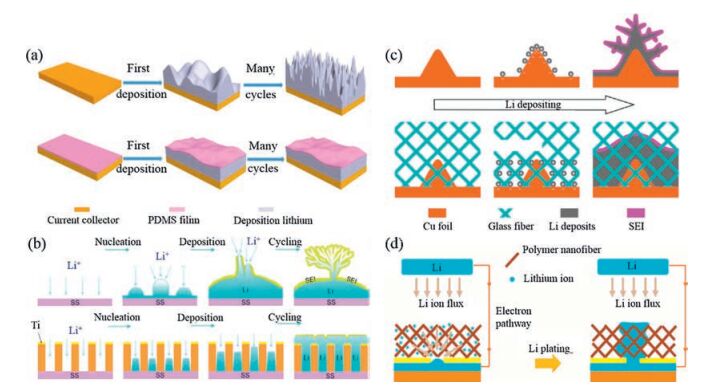
The porous PDMS film was introduced as the surface protective layer to improve the deposition of lithium metal and suppress the growth of lithium dendrites [83], as demonstrated in Fig. 7a. The porous PDMS film displays excellent flexibility, chemical resistance, and mechanical stability. The PDMS film is insulative to conduct neither electrons nor Li-ions, however, lithium ion flux is able to transport through the nanopores on the PDMS film. The pores on the PDMS film are prepared by chemical etching and they are relatively disorder, well-organized channels on the surface of lithium metal electrode have also been investigated. The polyimide layer with an ordered array of vertically aligned channels was prepared to regulate the lithium deposition, via manipulating lithium ion flux homogeneous distribution above the lithium electrode (Fig. 7b) [84]. Uniform lithium deposition without mossy-like morphology is expected for the modified electrode.

|
Download:
|
| Fig. 7. Suppression of the growth of lithium dendrites by artificial external matrix. (a) A thin PDMS film conformal to the growth surface suppresses the formation of lithium dendrites. Reproduced with permission [83]. Copyright 2017, Wiley-VCH. (b) An array of vertical-aligned nanochannels on the electrode ensures a uniform lithium ion flux and thus avoids the growth of lithium dendrites. Reproduced with permission [84]. Copyright 2016, American Chemical Society. Growth of lithium dendrites on the copper electrode could be suppressed by (c) an external glass fiber matrix or (d) a polymer nanofiber network. Figure c reproduced with permission [85]. Copyright 2017, Wiley-VCH. Figure d reproduced with permission [86]. Copyright 2015, American Chemical Society. | |
Instead of a surface protective layer, 3D porous structures of glass fibers with large quantities of Si—O, O—H and O—B polar functional groups (Fig. 7c) or partially oxidized polyacrylonitrile nanofibers with O—H, C=O and C—N polar functional groups (Fig. 7d) are employed respectively to suppress the growth of lithium dendrites [85, 86]. These frameworks are mechanically strong and could hinder the growth of lithium dendrites. In addition, the chemical interaction between the polar functional groups and the lithium ions also plays an important role in suppressing the lithium dendrites. Theoretical simulations indicate that the binding energy of lithium ions with those polar functional groups is larger than that with copper or lithium atoms. Therefore, the diffusion of lithium ions towards the protuberance of lithium metal is retarded by the chemical force from the polar functional groups and the preferential vertical deposition is mitigated.
4.3. Lithium ion conductive surface protective layerLithium ion conductors which exhibit ion-conducting and electron-insulating properties are considered as better surface protective materials than insulative materials. The surface protective layers prepared using lithium ion conductors can prevent the deposition of lithium on the layer surface, but facilitate the diffusion of lithium ions through the protective layer, resulting in uniform deposition of metallic lithium under the protective layer. For example, ion conductive surface protective layers of Cu3N nanoparticles embedded in a polymer matrix (Fig. 8a) and garnet nanoparticles in a PEO polymer matrix (Fig. 8b) have been developed as multifunctional layers to guide the lithium deposition [87, 88]. These layers have favorable ionic conductivity for the migration of lithium ions and desired flexibility to accommodate the volume change of metallic lithium during the plating and stripping process.

|
Download:
|
| Fig. 8. Suppression of lithium dendrites by an artificial SEI layer consisted of a polymer matrix and lithium-ion conducting nanoparticles embedded in the matrix. (a) Cu3N nanoparticles in a SBR polymer matrix. Reproduced with permission [87]. Copyright 2017, Wiley-VCH. (b) Garnet nanoparticles in a PEO polymer matrix. The artificial SEI layer is much more stable during the cycling. Reproduced with permission [88]. Copyright 2017, Springer. | |
4.4. Other surface protective layer
The functions of artificial surface protective layer are diverse, for example the flexible insulative layer and the lithium ion conductive layer are designed to act as a physical barrier in suppressing the growth of lithium dendrites. Other materials with new functions or different properties have been explored as the surface protective layer for lithium metal electrode, for example, the lithium conductive Li3N film [89-91]. Metallic lithium undergoes repeated uniform plating and stripping at the resultant electrode. Porous Al2O3 is also used as surface protective layer for lithium metal electrode due to its good chemical stability. By confining the deposition of lithium metal within the interstitial volume of a porous Al2O3 layer and isolating the confined lithium via a robust SEI layer, the Coulombic efficiency of the battery reaches high values of ~97%-99% [92]. In addition, it has been shown that a conformal and ultrathin Al2O3 coating prepared by atomic layer deposition could enhance the wettability of the lithium surface towards both carbonate and ether electrolytes, leading to uniform and dense SEI formation and homogeneous lithium deposition [93]. Because of its high electronic conductivity, high mechanical strength and stable electrochemistry, considerable efforts have been made to explore the feasibility of using carbon materials as surface protective layer to suppress the growth of lithium dendrites [94-98]. For example, long battery life cycle with high Coulombic efficiency could be achieved after coating a stable layer of hollow carbon nanospheres [94].
Generally, an ideal candidate should be chemically and electrochemically stable, mechanically robust and highly flexible, which is able to form a stable layer conformal to the surface of the electrode. Although diverse artificial surface protective layers have been proposed, complete investigations into the specific roles of the influencing factors, such as surface lithiophilicity, electrical conductivity, ionic conductivity, pore structure and surface area, are inadequate. Optimizing the artificial surface protective layer and developing a facile method to fabricate the composite lithium metal electrode are of essential significance. Herein, the interfacial protection effects of different artificial surface protective layers are summarized in Table 1.
|
|
Table 1 Summary of the artificial surface protective layer for lithium metal electrode. |

5. Conclusion and outlook
Lithium metal, due to its high theoretical specific capacity, low gravimetric density and lowest negative redox potential, is a promising material for high-energy-density storage systems and recent developments of lithium metal battery is encouraging. Many improvements of lithium metal batteries have been done to achieve the uniform deposition of lithium metal, inhibit the growth of lithium dendrites, maintain the high Columbic efficiency, and obtain the long term stability. These performances are regulated by many factors, such as the electric field, the lithium ion flux, the local current density, the SEI layer, and the nucleation and growth of lithium, which serve as the design principles for stable lithium metal battery. Different designs have been proposed and these methods, such as adding additives in the electrolytes, introducing a solid state electrolyte, using a mechanically strong separator and constructing a functional hybrid electrode, assists the deposition of lithium and suppresses the growth of lithium dendrites, thus improving the performance of lithium battery.
The three main strategies discussed herein focus on constructing a functional hybrid electrode, which is able to inhibit the growth of lithium dendrites from different perspectives, and each of them has its peculiar advantage and disadvantage. The nanostructured 3D porous current collector is beneficial to ensure a more uniform electric field and lithium ion flux; the rationally designed lithium host materials is of vital importance to relieve the large volume change during the plating and stripping process; the artificial surface protective layer blocks the direct contact between lithium and electrolytes, avoiding the continual consumption of lithium and electrolytes. A joint solution combining all the advantages will be more powerful to achieve a safer and more efficient lithium metal battery, which could open up a new opportunity for high-energy-density storage systems.
The future development of lithium metal batteries will benefit from the researches of other disciplines. The emerging of advanced materials and new technologies will provide emerging chances to improve the performance and the safety. For example, carbon materials, due to their high electronic conductivity, high mechanical strength, stable electrochemistry and low cost, are widely studied in many areas and now have been extensively investigated as crucial candidates of advanced composite electrodes for lithium metal battery. Theoretical and experimental works that aim to understand the fundamental chemistry/electrochemistry taking place in lithium metal systems and unveil the intrinsic instability of lithium deposition are of key importance. The improved understanding of the deposition behavior of metallic lithium, such as the dynamics of the lithium ion flux during the plating and the stripping place, and the interaction between lithium and current collectors, such as the lithium bonding, will provide new guidance to solve the problem of lithium metal battery.
For widespread commercial applications, a facile route that could scale up the production needs to be explored, since current research is mostly conducted in coin cells with a low current density, which cannot meet the requirements of practical full batteries. The cost of the battery may also become an important issue. We believe that the contributions of various researches will pave the way for the commercial applications of lithium metal battery.
AcknowledgmentsWe gratefully acknowledge the financial support from the National Natural Science Foundation of China (Nos. 21602205, 11704331) and Natural Science Foundation of Zhejiang Province (No. LQ18B030004). We thank Prof. Qiang Zhang for helpful discussions.
| [1] |
L. Kazmerski, Renew. Sustain. Energy Rev. 38(2013) 834-847. |
| [2] |
R.F. Service, Science 332(2011) 293. DOI:10.1126/science.332.6027.293 |
| [3] |
C. Liu, F. Li, L.P. Ma, H.M. Cheng, Adv. Mater. 22(2010) E28-E62. DOI:10.1002/adma.v22:8 |
| [4] |
S. Chu, A. Majumdar, Nature 488(2012) 294-303. DOI:10.1038/nature11475 |
| [5] |
B. Dunn, H. Kamath, J.M. Tarascon, Science 334(2011) 928-935. DOI:10.1126/science.1212741 |
| [6] |
K. Amine, R. Kanno, Y. Tzeng, MRS Bull. 39(2014) 395-401. DOI:10.1557/mrs.2014.62 |
| [7] |
J.B. Goodenough, K.S. Park, J. Am. Chem. Soc. 135(2013) 1167-1176. DOI:10.1021/ja3091438 |
| [8] |
J.B. Goodenough, Y. Kim, Chem. Mater. 22(2010) 587-603. DOI:10.1021/cm901452z |
| [9] |
J.M. Tarascon, M. Armand, Nature 414(2001) 359-367. DOI:10.1038/35104644 |
| [10] |
W. Xu, J.L. Wang, F. Ding, et al., Energy Environ. Sci. 7(2014) 513-537. DOI:10.1039/C3EE40795K |
| [11] |
X.B. Chen, R. Zhang, C.Z. Zhao, Q. Zhang, Chem. Rev. 117(2017) 10403-10473. DOI:10.1021/acs.chemrev.7b00115 |
| [12] |
M.D. Tikekar, S. Choudhury, Z.Y. Tu, L.A. Archer, Nat. Energy 1(2016) 16114. DOI:10.1038/nenergy.2016.114 |
| [13] |
Y. Sun, N. Liu, Y. Cui, Nat. Energy 1(2016) 16071. DOI:10.1038/nenergy.2016.71 |
| [14] |
A. Manthiram, S.H. Chung, C.X. Zu, Adv. Mater. 27(2015) 1980-2006. DOI:10.1002/adma.v27.12 |
| [15] |
J.Q. Huang, Q. Zhang, F. Wei, Energy Storage Mater. 1(2015) 127-145. DOI:10.1016/j.ensm.2015.09.008 |
| [16] |
J. Liang, Z.H. Sun, F. Li, H.M. Cheng, Energy Storage Mater. 2(2016) 76-106. DOI:10.1016/j.ensm.2015.09.007 |
| [17] |
H.J. Peng, J.Q. Huang, Q. Zhang, Chem. Soc. Rev. 46(2017) 5237-5288. DOI:10.1039/C7CS00139H |
| [18] |
L.P. Yue, J. Ma, J.J. Zhang, et al., Energy Storage Mater. 5(2016) 139-164. DOI:10.1016/j.ensm.2016.07.003 |
| [19] |
C.W. Sun, J. Liu, Y.D. Gong, D.P. Wilkinson, J.J. Zhang, Nano Energy 33(2017) 363-386. DOI:10.1016/j.nanoen.2017.01.028 |
| [20] |
H. Ye, S. Xin, Y.X. Yin, Y.G. Guo, Adv. Energy Mater. 7(2017) 1700530. DOI:10.1002/aenm.v7.23 |
| [21] |
X.B. Cheng, R. Zhang, C.Z. Zhao, et al., Adv. Sci. 3(2016) 1500213. DOI:10.1002/advs.201500213 |
| [22] |
X. Chen, T.Z. Hou, B. Li, et al., Energy Storage Mater. 8(2017) 194-201. DOI:10.1016/j.ensm.2017.01.003 |
| [23] |
B.R. Lee, H.J. Noh, S.T. Myung, K. Amine, Y.K. Sun, J. Electrochem. Soc. 164(2016) A180-A186. |
| [24] |
C.P. Yang, K. Fu, Y. Zhang, E. Hitz, L.B. Hu, Adv. Mater. 29(2017) 1701169. DOI:10.1002/adma.201701169 |
| [25] |
Y.P. Guo, H.Q. Li, T.Y. Zhai, Adv. Mater. 29(2017) 1700007. DOI:10.1002/adma.201700007 |
| [26] |
D.R. Ely, R.E. García, J. Electrochem. Soc. 160(2013) A662-A668. DOI:10.1149/1.057304jes |
| [27] |
X.X. Zeng, Y.X. Yin, N.W. Li, et al., J. Am. Chem. Soc. 138(2016) 15825-15828. DOI:10.1021/jacs.6b10088 |
| [28] |
X.Q. Zhang, X.B. Cheng, X. Chen, Funct. Mater. 27(2017) 1605989. DOI:10.1002/adfm.v27.10 |
| [29] |
C.Z. Zhao, X.B. Chen, R. Zhang, et al., Energy Storage Mater. 3(2016) 77-84. DOI:10.1016/j.ensm.2016.01.007 |
| [30] |
X.B. Cheng, C. Yan, X. Chen, et al., Chemistry 2(2017) 258-270. DOI:10.1016/j.chempr.2017.01.003 |
| [31] |
Y. Yamada, K. Furukawa, K. Sodeyama, et al., J. Am. Chem. Soc. 136(2014) 5039-5046. DOI:10.1021/ja412807w |
| [32] |
Z. Tu, P. Nath, Y. Lu, M.D. Tikekar, L.A. Archer, Acc. Chem. Res. 48(2015) 2947-2956. DOI:10.1021/acs.accounts.5b00427 |
| [33] |
Y.Y. Lu, S.K. Das, S.S. Moganty, L.A. Archer, Adv. Mater. 24(2012) 4430-4435. DOI:10.1002/adma.201201953 |
| [34] |
C. Yan, X.B. Chen, C.Z. Zhao, et al., J. Power Sources. 327(2016) 212-220. DOI:10.1016/j.jpowsour.2016.07.056 |
| [35] |
J. Wang, F. Lin, H. Jia, et al., Angew. Chem. Int. Ed. 53(2014) 10099-10104. DOI:10.1002/anie.201405157 |
| [36] |
H. Wu, Y. Cao, L. Geng, C. Wang, Chem. Mater. 29(2017) 3572-3579. DOI:10.1021/acs.chemmater.6b05475 |
| [37] |
K. Fu, Y.H. Gong, B.Y. Liu, Sci. Adv. 3(2016) e1601659. |
| [38] |
A. Manthiram, X. Yu, S. Wang, Nat. Rev. Mater. 2(2017) 16103. DOI:10.1038/natrevmats.2016.103 |
| [39] |
Y. Kato, S. Hori, T. Saito, Nat. Energy. 1(2016) 16030. DOI:10.1038/nenergy.2016.30 |
| [40] |
F.P. McGrogan, T. Swamy, S.R. Bishop, Adv. Energy Mater. 7(2017) 1602011. DOI:10.1002/aenm.201602011 |
| [41] |
Q. Ma, H. Zhang, C. Zhou, et al., Angew. Chem. Int. Ed. 55(2016) 2521-2525. DOI:10.1002/anie.201509299 |
| [42] |
C.Z. Zhao, X.Q. Zhang, X.B. Chen, et al., Proc. Natl. Acad. Sci. U. S. A. 114(2017) 11069-11074. DOI:10.1073/pnas.1708489114 |
| [43] |
W.D. Zhou, S.F. Wang, Y.T. Li, et al., J. Am. Chem. Soc. 138(2016) 9385-9388. DOI:10.1021/jacs.6b05341 |
| [44] |
Y. Pan, S. Chou, H.K. Liu, S.X Dou, Natl. Sci. Rev.(2017). DOI:10.1093/nsr/nwx037 |
| [45] |
Y. Liu, Q. Liu, L. Xin, Nat. Energy 2(2017) 17083. DOI:10.1038/nenergy.2017.83 |
| [46] |
J. Dai, C. Shi, C. Li, et al., Energy Environ. Sci. 9(2016) 3252-3261. DOI:10.1039/C6EE01219A |
| [47] |
S.O. Tung, S. Ho, M. Yang, R. Zhang, N.A Kotov, Nat. Commun. 6(2015) 6152. DOI:10.1038/ncomms7152 |
| [48] |
X. Hao, J. Zhu, X. Jiang, et al., Nano Lett. 16(2016) 2981-2987. DOI:10.1021/acs.nanolett.5b05133 |
| [49] |
X. Zhang, X. Cheng, Q. Zhang, J. Energy Chem. 25(2016) 967-984. DOI:10.1016/j.jechem.2016.11.003 |
| [50] |
X.B. Cheng, H.J. Peng, J.Q. Huang, F. Wei, Q. Zhang, Small. 21(2014) 4257-4263. |
| [51] |
S. Matsuda, Y. Kubo, K. Uosaki, S. Nakanishi, ACS Energy Lett. 2(2017) 924-929. DOI:10.1021/acsenergylett.7b00149 |
| [52] |
W. Liu, Y. Mi, Z. Weng, et al., Chem. Sci. 8(2017) 4285-4291. DOI:10.1039/C7SC00668C |
| [53] |
Y. Zhang, B. Liu, E. Hitz, et al., Nano Res. 10(2017) 1356-1365. DOI:10.1007/s12274-017-1461-2 |
| [54] |
C.P. Yang, Y.X. Yin, S.F. Zhang, N.W. Liu, Y.G. Guo, Nat. Commun. 6(2015) 8058. DOI:10.1038/ncomms9058 |
| [55] |
Q.B. Yun, Y.B. He, W. Lv, et al., Adv. Mater. 28(2016) 6932-6939. DOI:10.1002/adma.201601409 |
| [56] |
L.L. Lu, J. Ge, J.N. Yang, et al., Nano Lett. 16(2016) 4431-4438. DOI:10.1021/acs.nanolett.6b01581 |
| [57] |
Q. Li, S.P. Zhu, Y.Y. Lu, Adv. Funct. Mater. 27(2017) 1606422. DOI:10.1002/adfm.201606422 |
| [58] |
S.H. Wang, Y.X. Yin, T.T. Zuo, Adv. Mater. 29(2017) 1703729. DOI:10.1002/adma.201703729 |
| [59] |
Y.M. Sun, G.Y. Zheng, Z.W. She, et al., Chem. 1(2016) 287-297. DOI:10.1016/j.chempr.2016.07.009 |
| [60] |
X.B. Cheng, H.J. Peng, J.Q. Huang, et al., ACS Nano. 9(2015) 6373-6382. DOI:10.1021/acsnano.5b01990 |
| [61] |
A.Y. Zhang, X. Fang, C.F. Shen, Y.H. Liu, C.W. Zhou, Nano Res. 9(2016) 3428-3436. DOI:10.1007/s12274-016-1219-2 |
| [62] |
R. Zhang, X.B. Cheng, C.Z. Zhao, et al., Adv. Mater. 28(2016) 2155-2162. DOI:10.1002/adma.201504117 |
| [63] |
T.T. Zuo, X.W. Wu, C.P. Yang, Adv. Mater. 29(2017) 1700389. DOI:10.1002/adma.201700389 |
| [64] |
R. Zhang, N.W. Liu, X.B. Cheng, Adv. Sci. 4(2017) 1600445. DOI:10.1002/advs.201600445 |
| [65] |
H. Ye, S. Xin, Y.X. Yin, Y.G Guo, Adv. Energy Mater. 7(2017) 1700530. DOI:10.1002/aenm.v7.23 |
| [66] |
R. Zhang, X.R. Chen, X. Chen, et al., Angew. Chem. Int. Ed. 56(2017) 7764-7768. DOI:10.1002/anie.201702099 |
| [67] |
C.B. Jin, O. Sheng, J.M. Luo, et al., Nano Energy 37(2017) 177-186. DOI:10.1016/j.nanoen.2017.05.015 |
| [68] |
C.P. Yang, Y.G. Yao, S.M. He, Adv. Mater. 29(2017) 1702714. DOI:10.1002/adma.201702714 |
| [69] |
K. Yan, Z.D. Lu, H.W. Lee, Nat. Energy. 1(2016) 16010. DOI:10.1038/nenergy.2016.10 |
| [70] |
D.C. Lin, Y.Y. Liu, Z. Liang, et al., Nat. Nanotechnol. 11(2016) 626-632. DOI:10.1038/nnano.2016.32 |
| [71] |
Z. Liang, D. Lin, J. Zhao, et al., Proc. Natl. Acad. Sci. U. S. A. 113(2016) 2862-2867. DOI:10.1073/pnas.1518188113 |
| [72] |
Y. Zhang, W. Luo, C. Wang, et al., Proc. Natl. Acad. Sci. U. S. A. 114(2017) 3584-3589. DOI:10.1073/pnas.1618871114 |
| [73] |
S.S. Chi, Y.C. Liu, W.L. Song, L.Z. Fan, Q. Zhang, Adv. Funct. Mater. 27(2017) 1700348. DOI:10.1002/adfm.v27.24 |
| [74] |
D.C. Lin, J. Zhao, J. Shun, et al., Proc. Natl. Acad. Sci. U. S. A. 114(2017) 4613-4618. DOI:10.1073/pnas.1619489114 |
| [75] |
J. Zhao, G.M. Zhou, K. Yan, et al., Nat. Technol. 12(2017) 993-999. |
| [76] |
S. Choudhury, L.A. Archer, Adv. Electron. Mater. 2(2016) 1500246. DOI:10.1002/aelm.201500246 |
| [77] |
K. Kanamura, S. Shiraishi, Z. Takehara, J. Fluor. Chem. 87(1998) 235-243. DOI:10.1016/S0022-1139(97)00151-6 |
| [78] |
S. Shiraishi, K. Kanamura, Z. Takehara, J. Electrochem. Soc. 146(1999) 1633-1639. DOI:10.1149/1.1391818 |
| [79] |
Y.Y. Lu, Z.Y. Tu, L.A. Archer, Nat. Mater. 13(2014) 961-969. DOI:10.1038/nmat4041 |
| [80] |
X.Q. Zhang, X. Chen, R. Xu, et al., Angew. Chem. Int. Ed. 56(2017) 14207-14211. DOI:10.1002/anie.201707093 |
| [81] |
D.C. Lin, Y.Y. Liu, W. Chen, et al., Nano Lett. 17(2017) 3731-3737. DOI:10.1021/acs.nanolett.7b01020 |
| [82] |
Z. Peng, N. Zhao, Z.G. Zhang, et al., Nano Energy 39(2017) 662-672. DOI:10.1016/j.nanoen.2017.07.052 |
| [83] |
B. Zhu, Y. Jin, X. Hu, Adv. Mater. 29(2017) 1603755. DOI:10.1002/adma.v29.2 |
| [84] |
W. Liu, D. Lin, A. Pei, Y. Cui, J. Am. Chem. Soc. 138(2016) 15443-15450. DOI:10.1021/jacs.6b08730 |
| [85] |
X.B. Cheng, T.Z. Hou, R. Zhang, et al., Adv. Mater. 28(2016) 2888-2895. DOI:10.1002/adma.201506124 |
| [86] |
Z. Liang, G. Zheng, C. Liu, et al., Nano Lett. 15(2015) 2910-2916. DOI:10.1021/nl5046318 |
| [87] |
Y.Y. Liu, D.C. Lin, P.Y. Yuen, Adv. Mater. 29(2017) 1605531. DOI:10.1002/adma.201605531 |
| [88] |
C.P. Yang, B.Y. Liu, F Jiang, Nano Res.(2017). DOI:10.1007/s12274-017-1498-2 |
| [89] |
M.F. Wu, Z.Y. Wen, Y. Liu, X.Y. Wang, L.Z. Huang, J. Power Sources 196(2011) 8091-8097. DOI:10.1016/j.jpowsour.2011.05.035 |
| [90] |
M. Baloch, D. Shanmukaraj, O. Bondarchuk, et al., Energy Storage Mater. 9(2017) 141-149. DOI:10.1016/j.ensm.2017.06.016 |
| [91] |
Y.J. Zhang, W. Wang, H. Tang, et al., J. Power Sources 277(2015) 304-311. DOI:10.1016/j.jpowsour.2014.12.023 |
| [92] |
Z. Peng, S. Wang, J. Zhou, et al., J. Mater. Chem. A 4(2016) 2427-2432. DOI:10.1039/C5TA10050J |
| [93] |
L. Chen, J.G. Connell, A. Nie, et al., J. Mater. Chem. A 5(2017) 12297-12309. DOI:10.1039/C7TA03116E |
| [94] |
G. Zheng, S.W. Lee, Z. Liang, et al., Nat. Nanotechnol. 9(2014) 618-623. DOI:10.1038/nnano.2014.152 |
| [95] |
D. Zhang, Y. Zhou, C. Liu, S.S. Fan, Nanoscale 8(2016) 11161-11167. DOI:10.1039/C6NR00465B |
| [96] |
J.S. Kim, D.W. Kim, H.T. Jung, J.W. Choi, Chem. Mater. 27(2015) 2780-2787. DOI:10.1021/cm503447u |
| [97] |
S.Y. Huang, L. Tang, H.S. Najafabadi, S. Chen, Z.F. Ren, Nano Energy 38(2017) 504-509. DOI:10.1016/j.nanoen.2017.06.030 |
| [98] |
Z. Zhang, Z. Peng, J. Zheng, J. et al, Mater. Chem. A 5(2017) 9339-9349.
|
| [99] |
J. Song, H. Lee, M.J. Choo, J.K. Park, H.T. Kim, Sci. Rep. 5(2015) 14458. DOI:10.1038/srep14458 |
| [100] |
N.W. Li, Y.X. Yin, C.P. Yang, Y.G. Guo, Adv. Mater. 28(2016) 1853-1858. DOI:10.1002/adma.201504526 |
| [101] |
J. Luo, C.C. Fang, N.L. Wu, Adv. Energy Mater. 6(2017) 1701482. |
| [102] |
K. Liu, A. Pei, H. Lee, et al., J. Am. Chem. Soc. 139(2017) 4815-4820. DOI:10.1021/jacs.6b13314 |
| [103] |
K. Yan, H.W. Lee, T. Gao, et al., Nano Lett. 14(2014) 6016-6022. DOI:10.1021/nl503125u |
| [104] |
X. Liang, Q. Pang, I.R. Kochetkov, Nat. Energy 2(2017) 17119. DOI:10.1038/nenergy.2017.119 |