 2017, Vol. 28


Oxygen reduction reaction (ORR) is critically important for many advanced electrochemical energy conversion devices such as metal-air batteries, fuel cells, and chlor-alkali electrolyzers. Developing low-cost and high-performance electrocatalysts to replace the currently used Pt-based materials is highly desirable for successful implementation of above electrochemical devices in the near future [1-5]. Therefore, great efforts have been devoted to synthesizing efficient, durable, and inexpensive nonprecious metal catalysts (NPMCs). Recently, heteroatom-doped porous carbons and their nanocomposites with metal oxides/carbides have emerged as one of the most promising NPMCs for ORR due to their unique electronic and structural properties [4, 6-17]. In particular, transition metal-nitrogen-doped carbons (M-N-C, M = Fe, Co, etc.) which can be derived from various low-cost carbon precursors are very promising for ORR applications owing to their high ORR activity in both alkaline and acidic electrolytes [18-20]. Moreover, recent studies also showed that encapsulating metal or metal carbide nanoparticles into porous carbons could further enhance the ORR activity [20-26]. Although the nature of active sites in these catalysts has not been fully understood, the active sites are believed to be the surrounding Fe-Nx and N-C species which are activated by the encapsulated nanoparticles [20-27].
To achieve high ORR activity, it is crucial to simultaneously tune the active sites and porous structure to facilitate the redox reaction and mass transfer process [28, 29]. Thus, it is also important to properly design the porous structure to maximize the accessible active sites and promote the mass transport. Templating is an effective method to synthesize various porous carbon-based NPMCs [23, 29]. However, despite tremendous efforts, simple and effective templating methods which can lead to the desired electrocatalysts with ORR activity comparable to Pt/C have rarely been achieved so far.
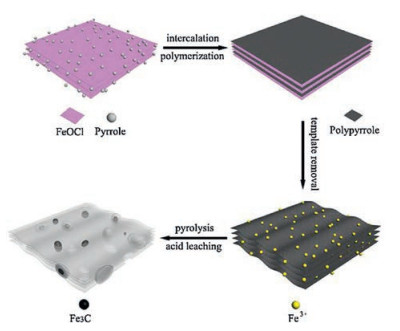
Herein, we demonstrate the synthesis of mesoporous Fe-Ndoped carbons with encapsulated Fe3C nanoparticles (hereafter referred to as the Fe3C/Fe-N-C catalyst) using a facile hardtemplating method with nitrogen-enriched polypyrrole (PPy) as the carbon precursor. Unlike previous templating methods which usually involved using SiO2 as the template, we developed FeOCl with a layered structure as a novel template for the preparation of NMPCs. As a laminar compound, FeOCl has been reported to be a suitable host for intercalation and polymerization of many guest compounds such as pyrrole and aniline [30, 31]. The FeOCl was first used as a template to prepare three-dimensional porous PPy structure (PPy@FeOCl). After removing FeOCl by acid leaching under ambient conditions, the porous PPy structure can be retained and converted into mesoporous carbons after pyrolysis. Meanwhile, the Fe3+ absorbed on porous PPy during the acid leaching process can act as the Fe sources for simultaneous formation of Fe3C nanoparticles and Fe-N-C active sites. Consequently, the as-prepared Fe3C/Fe-N-C catalyst could exhibit superior ORR performance to the commercial Pt/C catalyst (20 wt% Pt, Johnson Matthey) in the alkaline electrolyte. The two-electrode Zn-air battery assembled using the newly synthesized catalyst as the air electrode shows a peak discharge power density of 235 mW/cm2 and a large energy density of 901 Wh/kg at 50 mA/cm2.
The overall synthetic process is schematically illustrated in Scheme 1. FeOCl is a known inorganic material with a layered structure [30-32]. The interlayer space between the neighboring layers can accommodate pyrrole monomers to form an intercalative compound. Meanwhile, the pyrrole monomers can polymerize between the FeOCl layers to form PPy@FeOCl structure [30, 33]. The FeOCl template could be removed by a simple acid washing process. In this way, the dissolved Fe3+ can adsorb on PPy structure. After pyrolysis and acid leaching to remove unstable and electrochemically inactive species, mesoporous Fe3C/Fe-N-C catalysts were finally obtained by annealing the sample under the same temperature. During the pyrolysis and leaching process, removing unstable iron moieties could lead to the formation of the mesoporous structure which is favorable for enhancing mass transfer and accessibility of actives sites for ORR.

|
Download:
|
| Scheme 1. Schematic illustration for the preparation of mesoporous Fe3C/Fe-N-C catalyst. | |
Previous reports have shown that different pyrolysis conditions played a crucial role in the electrocatalytic activity of porous carbon-based catalysts [23, 34]. Therefore, the Fe3C/Fe-N-C catalysts obtained from different pyrolysis temperatures (700–1000 ℃) were first evaluated with rotating disk electrode (RDE) in O2-saturated 0.1 mol/L KOH electrolyte. Obviously, the Fe3C/FeN-C catalyst pyrolyzed under 800 ℃ (Fe3C/Fe-N-C-800) exhibited the best ORR performance as revealed from the onset potential (Eonset), half-wave potential (E1/2), and diffusion-limited current density in linear sweep voltammetry (LSV) curves (Fig. S1 in Supporting information). This is likely a collective outcome of the optimized porous structure, formation of Fe3C nanoparticles, type and density of active sites achieved under this temperature [23, 29, 34-38]. Therefore, the Fe3C/Fe-N-C catalyst discussed below was prepared at 800 ℃ unless otherwise specified.
The layer-structured FeOCl template can be conveniently prepared from FeCl3 by thermal treatment (for details see Experimental Section, Fig. S2 in Supporting information) [32]. The successful intercalation and polymerization of pyrrole into PPy were verified by the shift of the (002) peak of FeOCl from 11.30° (d = 0.79 nm) to 6.68° (d = 1.31 nm) in the powder X-ray diffraction (PXRD) pattern (Fig. S3 in Supporting information). Morphology of the FeOCl template was retained in PPy@FeOCl as judged from the scanning electron microscope (SEM) image (Fig. 1a). After removing the FeOCl template using HCl, a porous PPy structure was obtained and the structure was similar to that of the FeOCl template (Fig. 1b) [33]. Subsequent thermal treatment of the porous PPy structure at 800 ℃ and acid leaching could lead to the final mesoporous Fe3C/Fe-N-C-800 catalyst. The SEM and transmission electron microscope (TEM) images of Fe3C/Fe-N-C-800 catalyst obtained by pyrolyzing at 800 ℃ are shown in Fig. 1c. and Fig. S4 (Supporting information), respectively. Nitrogen adsorption measurement was conducted to determine the porous structure of the as-prepared Fe3C/Fe-N-C-800 catalyst. The Fe3C/Fe-N-C-800 catalyst exhibited a typical type-Ⅳ isotherm with a pronounced hysteresis loop, suggesting the formation of desired mesoporous structure (Fig. 1d). The corresponding Brunauer-Emmett-Teller (BET) surface area and pore diameter were determined to be 145 m2/g and 4.5 nm, respectively.

|
Download:
|
| Fig. 1. (a–c) SEM images of (a) PPy@FeOCl, (b) porous PPy, and (c) Fe3C/Fe-N-C-800 catalyst. (d) N2 sorption isotherms and corresponding pore diameter distribution of the Fe3C/Fe-N-C-800 catalyst. | |
The crystalline nature of the Fe3C/Fe-N-C-800 catalyst was characterized by PXRD. As shown in Fig. S5 (Supporting information), the peak at about 26.5° can be indexed to the (002) plane of graphitic carbon. The other diffraction peaks can be assigned to the crystalline Fe3C (JCPDS 35-0772). Bulk elemental analysis and inductively coupled plasma atomic emission spectroscopy (ICPAES) indicated that the C, N, O and Fe contents in Fe3C/Fe-N-C-800 were 87.22, 4.29, 3.52 and 4.15 wt%, respectively, with a trace amount of H (0.82 wt%). The X-ray photoelectron spectroscopy (XPS) survey spectrum is shown in Fig. S6 (Supporting information), confirming the existence of C (284.7 eV), O (531.4 eV), N (399.5 eV) and Fe (719.9 eV) in the Fe3C/Fe-N-C-800 catalyst. Meanwhile, the surface elemental composition is calculated to be 88.92, 5.9, 4.4, and 0.78 at% for C, N, O and Fe, respectively. The Fe content measured from XPS (3.45 wt%) is lower than that obtained from ICP-AES (4.15 wt%), implying that part of Fe species are embedded within the porous carbon matrix. High-resolution N 1 s XPS spectrum (Fig. S7a in Supporting information) revealed the presence of various N species including pyridinic N (398.4 eV), pyrrolic N (399.9 eV), graphitic N (401.2 eV) and oxidized N (404.0 eV). The pyridinic N, pyrrolic N and graphitic N were reported to be beneficial for ORR [29, 35, 36]. The high-resolution Fe 2p spectrum (Fig. S7b in Supporting information) can be deconvoluted into two pairs of peaks for Fe3+ (714.1 and 726.8 eV) and Fe2+ (711.3 and 724.6 eV) with a satellite peak at 719.3 eV. The peak at 711.3 eV in the Fe 2p3/2 XPS spectrum suggests the existence of Fe-Nx species which are active sites for ORR.
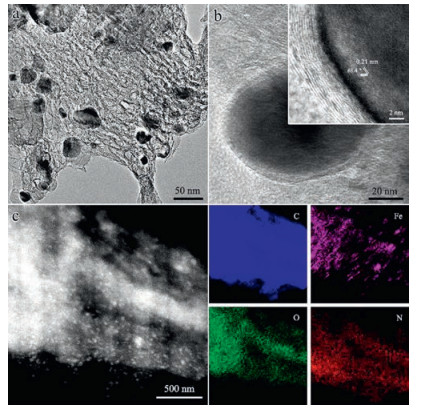
Further examination of the Fe3C/Fe-N-C-800 catalyst using TEM indicated that the as-synthesized catalyst was mesoporous and embedded with nanoparticles (Fig. 2a). The graphitic carbons could be easily identified by high-resolution TEM (HRTEM, Fig. 2b), showing a typical 0.34 nm interlayer spacing of the graphite (002) plane. The observed graphitic carbon shell should be beneficial for enhancing the stability of the catalyst [21-26]. Moreover, the spacing of crystalline lattices in two directions are both 0.21 nm with a characteristic intersection angle of 68.4° for the embedded crystalline nanoparticles, corresponding to the (211) and (-211) planes of the Fe3C phase [21, 23, 25]. The high angle annular dark field-scanning transmission electron microscopy (HAADF-STEM) result confirmed that the crystalline Fe3C nanoparticles were homogeneously dispersed in the carbon skeleton (Fig. 2c). Elemental mapping results further demonstrated that N was homogeneously distributed in the carbon matrix. In contrast, strong Fe signals mainly existed in the nanoparticle areas. It is known that the encapsulated Fe3C nanoparticles are able to activate the surrounding graphitic carbons or Fe-Nx species [21, 37, 38]. Therefore, the encapsulated Fe3C nanoparticles formed during pyrolysis in the mesoporous carbon matrix should be crucial for enhancing ORR performance.

|
Download:
|
| Fig. 2. (a) TEM image of the Fe3C/Fe-N-C-800 catalyst. (b) HRTEM images of a single Fe3C nanoparticle encapsulated in a graphitic carbon shell with the index crystal plane displayed in the inset. (c) HAADF-STEM image of Fe3C/Fe-N-C-800 and the corresponding elemental mapping images of C, O, N and Fe. | |
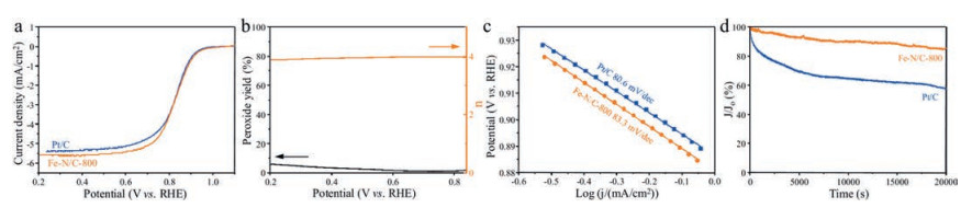
To evaluate the ORR activity of Fe3C/Fe-N-C-800, cyclic voltammetry (CV) measurements were first carried out in O2-and Ar-saturated 0.1 mol/L KOH electrolyte, respectively. Meanwhile, a commercial Pt/C catalyst (20 wt%, Johnson Matthey) was used for comparison. As shown in Fig. S8 (Supporting information), no obvious cathodic peak can be found in Ar-saturated electrolyte. In contrast, a typical cathodic peak at 0.82 V versus reversible hydrogen electrode (RHE) was observed. This value is very close to that of Pt/C catalyst (0.83 V vs. RHE), indicating that the Fe3C/Fe-NC-800 catalyst possesses prominent ORR activity. The LSV curve shown in Fig. 3a further confirms that Fe3C/Fe-N-C-800 catalyst possesses excellent ORR activity with Eonset of 0.99 V vs. RHE and E1/2 of 0.83 V vs. RHE. These values are superior to those of Pt/C measured under the same conditions (Eonset~0.97 V and E1/2~0.82 V). Moreover, the diffusion-limited current density of the Fe3C/Fe-N-C-800 catalyst is higher than that of Pt/C. These results confirm that the Fe3C/Fe-N-C-800 catalyst exhibits more attractive ORR performance than Pt/C. We also conducted a control experiment to reveal the importance of the Fe3C nanoparticles for observed ORR activity. After ball milling and selectively leaching out Fe3C nanoparticles, the Fe-N-C-800 catalyst lost the prominent ORR performance (Fig. S9 in Supporting information), revealing the importance of the Fe3C nanoparticles in promoting the ORR activity.

|
Download:
|
| Fig. 3. (a) LSV curves of Fe3C/Fe-N-C-800 and 20 wt% Pt/C in O2-saturated 0.1 mol/L KOH electrolyte. (b) H2O2 yield and electron transfer number of Fe3C/Fe-N-C-800 calculated from RRDE measurements in O2-saturated 0.1 mol/L KOH electrolyte. (c) Tafel slopes derived from RDE measurements of Fe3C/Fe-N-C-800 and 20 wt% Pt/C in (a). (d) Chronoamperometric curves of Fe3C/Fe-N-C-800 and 20 wt% Pt/C at 0.7 V vs. RHE. Electrode rotating speed: 1600 rpm; scan rate: 10 mV/s. | |
Rotating ring-disk electrode (RRDE) measurements were further carried out to investigate the catalytic performance of Fe3C/Fe-N-C-800 (Fig. 3b). The average electron transfer number (n) calculated from RRDE measurement is 3.94, confirming a fourelectron dominated ORR pathway. This value is close to the results calculated from Koutecky-Levich equation (n = 3.95 ~ 4.05, Fig. S10 in Supporting information). The H2O2 yield was calculated to be less than 6% in the entire measured potential range and dropped to ~1% at 0.7 V vs. RHE, indicating that Fe3C/Fe-N-C-800 is very efficient in catalyzing O2 into OH- in alkaline electrolytes. The Fe3C/Fe-N-C-800 catalyst shows a Tafel slope of 83.3 mV/decade which is close to that of the Pt/C catalyst (80.6 mV/decade), implying that Fe3C/Fe-N-C-800 has a good kinetic process for ORR (Fig. 3c). The stability of Fe3C/Fe-N-C-800 and Pt/C were both investigated by chronoamperometric tests at 0.7 V vs. RHE in O2-saturated 0.1 mol/L KOH electrolyte. As shown in Fig. 3d, 85% of the original current density is retained after 20, 000 s for the Fe3C/FeN-C-800 catalyst whereas the current density of Pt/C shows a sharp loss of 40%. In addition, the Fe3C/Fe-N-C-800 catalyst was found to exhibit much better tolerance against methanol crossover than Pt/C. As shown in Fig. S11 (Supporting information), adding methanol into the KOH electrolyte could not lead to any obvious change in both CV and LSV curves for the Fe3C/Fe-N-C-800 catalyst. In sharp contrast, an obvious and typical methanol oxidation reaction can be observed from the CV curve for Pt/C catalyst. Moreover, an obvious negative shift of E1/2 can be observed in O2-saturated 0.1 mol/L KOH electrolyte (Fig. S12 in Supporting information). These results suggest that the Fe3C/Fe-N-C-800 catalyst possesses superior stability to the Pt/C catalyst, implying that the newly developed catalyst is very promising for future applications in ORR-related electrochemical devices with high stability.
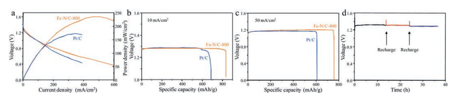
To further investigate the potential application of the Fe3C/FeN-C-800 catalyst for practical energy conversion devices, a primary Zn-air battery was fabricated using Fe3C/Fe-N-C-800 as the cathode catalyst. Meanwhile, commercial Pt/C catalyst was also tested under the same condition for comparison. As shown in Fig. S13 (Supporting information), the Zn-air battery assembled using the Fe3C/Fe-N-C-800 catalyst displays a high open-circuit voltage of 1.48 V. This value is higher than that of Pt/C (1.46 V). Fig. 4a shows the polarization curves of Zn-air batteries assembled using Fe3C/Fe-N-C-800 and Pt/C, respectively. The discharge potential and power density at low current densities are very close for both batteries. However, the Zn-air battery assembled using Fe3C/Fe-N-C-800 exhibits much higher discharge potential and power density at high current densities. The peak power density of Zn-air battery using Fe3C/Fe-N-C-800 is 235 mW/cm2, surpassing that of the Zn-air battery assembled using Pt/C catalyst (178 mW/cm2). Galvanostatic discharge tests at 10 mA/cm2 and 50 mA/cm2 show that the performance of Fe3C/Fe-N-C-800-based Zn-air battery is superior to that of Pt/C-based Zn-air battery (Fig. 4b and c). The specific capacity normalized to the mass of consumed Zn is 834 mAh/g and 751 mAh/g for Zn-air battery using the Fe3C/Fe-N-C-800 catalyst (corresponding to an energy density of ~1059 Wh/kg and ~901 Wh/kg) at 10 mA/cm2 and 50 mA/cm2, respectively. These values are much higher than the Zn-air battery using Pt/C catalyst (878 Wh/kg and 717 Wh/kg at 10 mA/cm2 and 50 mA/cm2, respectively), indicating the excellent ORR activity of Fe3C/Fe-N-C-800 in practical Zn-air batteries. More importantly, the Zn-air battery can be recovered by refueling the Zn anode and electrolyte multiple times without obvious voltage loss (Fig. 4d), implying excellent stability of the Fe-N-C-800 catalyst under practical conditions.

|
Download:
|
| Fig. 4. (a) Polarization curves and corresponding power density curves of Zn-air batteries assembled with Fe3C/Fe-N-C-800 and Pt/C catalysts. Galvanostatic discharge curves of Zn-air batteries with Fe3C/Fe-N-C-800 and Pt/C as cathode catalysts at two different current densities (b) 10 mA/cm2 and (c) 50 mA/cm2. (d) Long-term durability of the Znair battery using Fe3C/Fe-N-C-800 catalyst at a current density of 5 mA/cm2. | |
In conclusion, we demonstrate a novel template approach for the synthesis of mesoporous Fe3C/Fe-N-C catalyst for efficient and durable ORR. Unlike previous approaches which generally involve the use of SiO2 templates, a simple and easy-to-remove FeOCl template was developed for the synthesis of porous PPy structure which can then be converted into mesoporous carbon-based catalysts for ORR. More importantly, the as-synthesized Fe3C/Fe-NC catalyst exhibits excellent catalytic activity and stability for ORR, not only in half reactions but also in real Zn-air batteries. This study provides a new design strategy for preparing high-performance ORR catalysts for electrochemical energy storage and conversion devices.
AcknowledgmentsThis work was supported by the National Key Basic Research Program of China (No. 2015CB351903), National Natural Science Foundation of China (No. 51402282), China Postdoctoral Science Foundation (No. 2016M590579), and the Fundamental Research Funds for the Central Universities.
Appendix A. Supplementary dataSupplementary data associated with this article can be found, in the online version, at http://dx.doi.org/10.1016/j.cclet.2017.08.029.
| [1] |
G. Wu, P. Zelenay, Acc. Chem. Res. 46(2013) 1878-1889. DOI:10.1021/ar400011z |
| [2] |
R. Bashyam, P. Zelenay, Nature 443(2006) 63-66. DOI:10.1038/nature05118 |
| [3] |
R. Silva, D. Voiry, M. Chhowalla, T. Asefa, J. Am. Chem. Soc. 135(2013) 7823-7826. DOI:10.1021/ja402450a |
| [4] |
K. Gong, F. Du, Z. Xia, M. Durstock, L. Dai, Science 323(2009) 760-764. DOI:10.1126/science.1168049 |
| [5] |
Y. Li, H. Dai, Chem. Soc. Rev. 43(2014) 5257-5275. DOI:10.1039/C4CS00015C |
| [6] |
J. Liu, X. Sun, P. Song, Y. Zhang, W. Xing, W. Xu, Adv. Mater. 25(2013) 6879-6883. DOI:10.1002/adma.v25.47 |
| [7] |
Z. Wu, S. Yang, Y. Sun, et al., J. Am. Chem. Soc. 134(2012) 9082-9085. DOI:10.1021/ja3030565 |
| [8] |
Y. Ding, Y. Niu, J. Yang, et al., Small 12(2016) 5414-5421. DOI:10.1002/smll.v12.39 |
| [9] |
Y. Liang, Y. Li, H. Wang, et al., Nat. Mater. 10(2011) 780-786. DOI:10.1038/nmat3087 |
| [10] |
H. Song, Y. Ding, J. Yang, H. Xu, Chin. J. Chem. Phys. 29(2016) 693-698. DOI:10.1063/1674-0068/29/cjcp1605115 |
| [11] |
M. Zeng, Y. Liu, F. Zhao, et al., Adv. Funct. Mater. 26(2016) 4397-4404. DOI:10.1002/adfm.v26.24 |
| [12] |
Z. Ma, S. Dou, A. Shen, et al., Angew. Chem. Int. Ed. 54(2015) 1888-1892. DOI:10.1002/anie.201410258 |
| [13] |
J. Zhang, Z. Zhao, Z. Xia, L. Dai, Nat. Nanotechnol. 10(2015) 444-452. DOI:10.1038/nnano.2015.48 |
| [14] |
Q. Liu, Y. Wang, L. Dai, J. Yao, Adv. Mater. 28(2016) 3000-3006. DOI:10.1002/adma.201506112 |
| [15] |
Z.S. Wu, L. Chen, J. Liu, et al., Adv. Mater. 26(2014) 1450-1455. DOI:10.1002/adma.201304147 |
| [16] |
J. Wang, Z. Wu, L. Han, et al., Chin. Chem. Lett. 27(2016) 597-601. DOI:10.1016/j.cclet.2016.03.011 |
| [17] |
J. Xu, C. Xiao, S. Ding, Chin. Chem. Lett. 28(2017) 748-754. DOI:10.1016/j.cclet.2016.12.006 |
| [18] |
Y. Si, C. Chen, W. Yin, H. Cai, Chin. Chem. Lett. 21(2010) 983-986. |
| [19] |
Y. Si, Z. Xiong, C. Chen, P. Liu, H. Wu, Chin. Chem. Lett. 24(2013) 1109-1111. DOI:10.1016/j.cclet.2013.09.002 |
| [20] |
J. Yang, X. Wang, B. Li, et al., Adv. Funct. Mater. 27(2017) 1606497. DOI:10.1002/adfm.v27.17 |
| [21] |
Y. Hu, J.O. Jensen, W. Zhang, et al., Angew. Chem. Int. Ed. 53(2014) 3675-3679. DOI:10.1002/anie.v53.14 |
| [22] |
Y. Hou, T. Huang, Z. Wen, S. Mao, S. Cui, J. Chen, Adv. Energy Mater. 4(2014) 1400337-1400344. DOI:10.1002/aenm.201400337 |
| [23] |
Z. Wu, X. Xu, B. Hu, et al., Angew. Chem. Int. Ed. 54(2015) 8179-8183. DOI:10.1002/anie.201502173 |
| [24] |
M. Xiao, J. Zhu, L. Feng, C. Liu, W. Xing, Adv. Mater. 27(2015) 2521-2527. DOI:10.1002/adma.201500262 |
| [25] |
J. Wei, Y. Liang, Y. Hu, et al., Angew. Chem. Int. Ed. 55(2016) 1355-1359. DOI:10.1002/anie.201509024 |
| [26] |
E. Xing, L. Liang, Y. Dong, W. Huang, Chin. Chem. Lett. 26(2015) 1322-1326. DOI:10.1016/j.cclet.2015.05.043 |
| [27] |
W. Jia, L. Gu, L. Li, et al., J. Am. Chem. Soc. 138(2016) 3570-3578. DOI:10.1021/jacs.6b00757 |
| [28] |
C. Zhu, H. Li, S. Fu, D. Du, Y. Lin, Chem. Soc. Rev. 45(2016) 517-531. DOI:10.1039/C5CS00670H |
| [29] |
W. Ding, Z. Wei, S. Chen, et al., Angew. Chem. Int. Ed. 52(2013) 11755-11759. DOI:10.1002/anie.v52.45 |
| [30] |
M.G. Kanatzidis, L.M. Tonge, T.J. Marks, J. Am. Chem. Soc. 109(1987) 3797-3799. DOI:10.1021/ja00246a057 |
| [31] |
C. Wu, D.C. DeGroot, H.O. Marcy, et al., J. Am. Chem. Soc. 117(1995) 9229-9242. DOI:10.1021/ja00141a015 |
| [32] |
Q. Li, J., Guo, C., Li, C., Xun, Q. Lv, CN Patent 102491429A, 2012.
|
| [33] |
N. Yanai, T. Uemura, M. Ohba, et al., Angew. Chem. Int. Ed. 120(2008) 10031-10034. DOI:10.1002/ange.v120:51 |
| [34] |
C.W.B. Bezerra, L. Zhang, H. Liu, et al., J. Power Sources 173(2007) 891-908. DOI:10.1016/j.jpowsour.2007.08.028 |
| [35] |
Y. Zhao, K. Watanabe, K. Hashimoto, J. Am. Chem. Soc. 134(2012) 19528-19531. DOI:10.1021/ja3085934 |
| [36] |
W. He, C. Jiang, J. Wang, L. Lu, Angew. Chem. Int. Ed. 53(2014) 9503-9507. DOI:10.1002/anie.201404333 |
| [37] |
F. Jaouen, F. Charreteur, J.P. Dodelet, J. Electrochem. Soc. 153(2006) A689-698. DOI:10.1149/1.2168418 |
| [38] |
J. Ozaki, S. Tanifuji, A. Furuichi, K. Yabutsuka, Electrochim. Acta 55(2010) 1864-1871. DOI:10.1016/j.electacta.2009.10.037 |