 2017, Vol. 28


Antireflective coatings (AR coatings) play a pivotal role in the increasing performance of optical components and photovoltaic/optoelectronic devices by increasing light transmission in optical systems as well as eliminating undesired reflections and glare [1-10]. To this end, many fabricating approaches, so-called top-down manufacturing, have been developed to produce the AR coatings including lithography [11-13], etching [13, 14], nano-imprinting [15], roll-to-roll [16], and so on [8, 17]. However, most of these topdown approaches are restricted by their multi-step processes involving complicated serial treating and expensive instruments, which decrease convenience and increase cost. In contrast to the technological fabrication, biological systems provide numerous examples of bottom-up strategies that could directly develop the function into their intricate architectures. Compound eyes of moths and other insects, for instance, as one of the highlighted examples, enable the direct growth of micropatterned antireflection coating with a curvilinear design of packed papillaelike ommatidia, which can focus light onto the internal photoreceptors and effectively decrease optical reflectance [18-20]. Inspired by the biology, to develop a bottom-up approach for AR coating mimicked the natural moth-eye is fascinating and challenging. Unfortunately, most of the traditional self-assembly techniques are not compatible with standard micro-fabrication, impeding scale-up to an industrial-scale fabrication [21]. Additionally, conventional self-assembly is limited to the creation of close-packed structures, whereas natural moth-eye AR coatings exhibit non-close-packing characteristics [19]. Generally, the biological surface patterns form spontaneously from the intersystem to the surface through one-step. So akin to the biological method, it is ideal to fabricate the complex patterned AR coatings through the complete "self-organizing" approach.
Recently, we have developed a one-step and bottom-up technology for preparing UV-induced wrinkling which combines the self-assembly of fluorinated additives with the volume shrinkage mismatch of top and inter multi-functional acrylate system for creating a large variety of macro/nano-structured films [22-24]. Based on this bottom-up technology of self-wrinkling, the complex patterned surface in large-scale was formed spontaneously from the intersystem to the surface through one step, which is akin to the biologic self-organizing method to generate wrinkled surface in nature. This approach for wrinkles is bottom-up and akin to the biological self-organizing method for generating a patterned surface in nature and can therefore be carried out easily over large areas at low cost [22-26]. Just like natural moth-eyes [18, 20], it is well known that the complex patterns in nano & micro-scale can reduce the light reflection of coating surface because of light trapping. Also, the one-step photopolymerization enable the facile and robust approach for large scale preparation [24, 27]. Motivated by the feasibility of self-wrinkling strategy to produce pattern, thus we herein extend our previous work on UV-induced self-wrinkling to prepare bio-inspired photo-curing coating with anti-reflection. With the different fluorinated copolymers, a series of biomimetic micro-structure with different morphology and size were one-step prepared as illustrated in Fig. 1 and the corresponding optical properties resulted from the incorporation of UV-induced wrinkles were focused on. Results indicate that the transmittance and antireflection of the photo-curing coating can be enhanced by the wrinkle pattern. The encapsulation of the thin film solar cells by the photo-curing coating can lead to obvious enhancement of its power conversion efficiency (PCE).

|
Download:
|
| Fig. 1. (a) The whole strategy to prepare the anti-reflection surface coating with wrinkle pattern. (b) Chemical structures of acrylate cross-linker and fluorinated copolymers used in this work. | |
The procedure for developing the anti-reflection surface coating with wrinkling pattern is illustrated in Fig. 1a. Firstly, fluorinated copolymers with different monomers such as methyl methacrylate, n-butylacrylate, styrene, poly(ethylene oxide) dimethacrylate (named as PMMA-F, PBA-F, PS-F and PEGMA-F, respectively, and detailed information seen Fig. 1b and Scheme S1 in Supporting information) as additives were dissolved in the acrylate crosslinker trimethylpropane triacrylate (TMPTA) with 0.3 wt% photoinitiator Irgacure 907, respectively. The mixed solution was then coated on the surface of glass substrate or solar cells by knife coating technique. Due to the low surface energy of the fluorinated chains, the fluorinated polymers additives can selfassemble at the interface which is open to the air to form the top layer. When the coating was exposed under UV light, the different shrinkage induced by photopolymerization between top and bulk layer can cause compressive stress, resulting in the wrinkle pattern simultaneously.
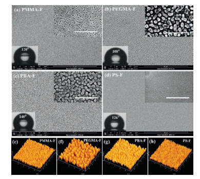
Figs. 2a–d show scanning electron microscope (SEM) images of the photo-curing coating surface with wrinkling pattern induced by PMMA-F, PBA-F, PS-F and PEGMA-F, respectively. The worm-like wrinkling pattern generated with PMMA-F and different nipplelike wrinkling patterns were obtained by PBA-F, PS-F and PEGMA-F, respectively. The different morphology is maybe due to the different structure and modulus of the fluorinated polymer additives. The characteristic period and amplitude of wrinkle pattern were investigated by the atomic force microscope (AFM) analysis. As shown in Figs. 2e–h, for PMMA-F induced wrinkles, the average period and amplitude are approximately 600 nm and 90 nm, respectively. For PBA-F and PEGMA-F induced wrinkles, the average period is approximately 800 nm and 1100 nm, respectively. For PS-F induced wrinkles, the average period and amplitude decrease obviously, and are approximately 300 nm and 60 nm, respectively, however, the PS-F induced wrinkling coating exhibits the larger aspect ratio among these wrinkling AR coatings, which is caused by the highest surface modulus of PS-F [22]. These results indicated that the morphology of wrinkling pattern can be tuned, and is dependent on the fluorinated polymers. It should be noted that the wrinkles pattern could enhance the hydrophobic properties of the photo-curing coating obviously. As shown in Figs. 2a–d, the water contact angles (WCA) of the photo-curing coating with wrinkle patterns are much bigger than that of the TPMPA wrinkle-free blank coating (70°). The WCA values of the PMMA-F and PS-F induced wrinkling films are approximately 120° and 126°, respectively, which are a little smaller than that of PBA-F induced wrinkling film (~140°). This might be due to the surface roughness of the PBA-F containing coating is bigger than that of the PMM-F and PS-F. The good hydrophobic property of the photocuring wrinkling coating should be due to the synergistic effect of the micropattern and fluorinated chain in the surface, suggesting the resulting coating with wrinkles can possess a self-cleaning function and be used as coating for some devices placed in the outdoor. Fig. S1 (Supporting information) shows the optical photographs of the UV-induced wrinkles coated silicon wafer under strong light, it can be observed that the mirror images of the strong light in the UV-induced wrinkles coated samples are dim compared with the uncoated samples, indicating that the UVinduced wrinkles exhibit the potential for reducing the light reflection. The shimmering iridescence should be ascribed to the strong thin-film interfere and light scattering, resulting from the introduction of wrinkles on the surface [28-30]. The wrinkling microstructures increase the optical path length through the photoactive layer and trap more light into the interface thus can influence more absorption of light [31, 32].

|
Download:
|
| Fig. 2. (a-d) SEM and (e-h) AFM images showing the anti-reflection surface coating with wrinkling pattern prepared by acrylate cross-linker TMPTA and fluorinated polymers (a, e) PMMA-F, (b, f) PBA-F, (c, g) PS-F and (d, h) PEGMA-F, respectively. The inset on the left bottom are the photos of water contact angles determined on the corresponding antireflective coating surface with wrinkling pattern prepared by different fluorinated polymers. The inset on the right upper is the magnification of the corresponding SEM images, and the scale bar is 5 μm. | |
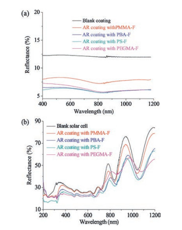
To evaluate the optical properties of the wrinkling AR coating, the transmittance and reflectance of these wrinkling AR coatings as well as blank TMPTA coating were studied by UV–vis–NIR Spectrophotometer with integrating sphere in a wavelength range from 400 nm to 1200 nm. As shown in Fig. 3a, the blank TMPTA film exhibits an average reflectivity approximately 12.5% for the whole wavelength range, while the reflectivity of the PMMA-F, PBA-F, PSF and PEGMA-F induced wrinkling AR coating decreased to 8%, 6%, 5% and 6%, respectively. These results achieve a same good AR performance of ~5% for single-side AR coatings fabricated by complicated top-down processes [8, 11-15]. All the wrinkling AR coatings exhibit much lower reflectivity than the flat blank coating due to the gradual aggregation of the fluorinated copolymer, which provides a gradual change of effective refractive index from air to the films and wrinkling patterns increase the internal scattering of incident light and effectively decrease the light reflection. Furthermore, we applied various wrinkling AR coating induced by different fluorinated polymers as well as blank TMPTA films to encapsulate α-Si thin film solar cells in one side. Fig. 3b shows the reflectance spectra of the bare α-Si solar cell device and devices coated with flat TMPTA, PBA-F and PS-F induced wrinkling TMPTA films measured with 8° incident angle. It can be seen that the reflectance of the bare device is approximately 28% for 400~800 nm wavelength range, which was decreased by ca. 4.5% with packaging of PS-F induced wrinkling AR coating. And the reflectivity of devices coated wrinkling films decreased more obviously in a wavelength range from 800 nm to 1200 nm compared with that of the bare devices.

|
Download:
|
| Fig. 3. Reflective curves of (a) blank coating, wrinkling AR coating prepared with PMMA-F/TMPTA, PBA-F/TMPTA, PS-F/TMPTA, PEGMA-F/TMPTA and (b) the corresponding packaged α-Si thin film solar cells. | |
The transmittance spectra corresponding to various wrinkling AR coating induced by different fluorinated polymers as well as blank TMPTA films were collected with incident angle of 0° (vertical) and 60°, respectively (Fig. S2 in Supporting information). The cured blank TMPTA film shows ~91.5% transmittance for the wavelength range of 400~800 nm with vertical incident angle. A drastic drop below the wavelength 400 nm might be due to the light absorption due to the photo initiator residues. The PMMA-F and PS-F induced wrinkling AR coatings show similar spectra and a little transmittance enhancement for 400~800 nm wavelength range. While the PBA-F and PEGMA-F induced wrinkling AR coatings exhibit different spectra compared to the blank TMPTA film. An obvious transmittance decease below 480 nm for PBA-F induced wrinkling film and 450 nm for PEGMA-F induced wrinkling film, and a continue transmittance increase for 500~800 nm wavelength range for both PBA-F and PEGMA-F induced wrinkling AR coatings are observed. The drastic drop below the wavelength 500 nm for PBA-F and PEGMA-F induced wrinkling AR coatings is attributed to not only the light absorption of the photo initiator residues but also the light scattering due to a large period of nipple micropattern compared with the wavelength of incident light. The continue transmittance increase for 500~800 nm wavelength range is maybe due to the mixed sizes of the wrinkling patterns. When the incident light angle changed to 60°, the transmittance of all the TMPTA films decreased. However, the PMMA-F, PBA-F, PS-F and PEGMA-F induced wrinkling TMPTA films showed 3%, 5%, 9% and 8% enhancement of the transmittance compared with the blank TMPTA film (Fig. S2b in Supporting information).
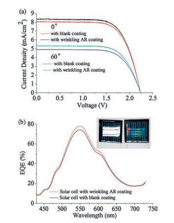
AR coating with wrinkling microstructures on the air side of the glass can increase the internal scattering of incident light and reduce optical losses due to air-glass-reflection at interface, effectively enhancing light harvesting efficiencies in solar cells [31-33]. Considering the well performance of lowest reflection and highest transmittance, the PS-F induced wrinkling AR coating with the highest aspect ratio was selected to encapsulate the thin film solar cells compared with the flat blank coated solar cells as reference to further evaluate the ability of wrinkling patterns to manipulate optical reflection. Three groups of tandem α-Si thin film solar cells packaged by PS-F induced wrinkling AR coating or flat blank TMPTA film as reference were tested using a solar simulator under the standard condition of AM 1.5G illumination [31] (1000 mW/cm2, 25 ℃), respectively. Fig. 4a presents the typical current density-voltage (J-V) characteristics of α-Si solar cells with flat cured TMPTA and PS-F induced wrinkling TMPTA films coating at an incident angle of 0° and 60°, respectively. A stable open-circuit voltage (Voc) of 2.2 V and fill factor (FF) of 67.2% were observed for the three polymer solar cells. While the short-circuit current density (Jsc) undergone a large change with surface wrinkling microstructures. For the flat blank devices, the average Jsc is around 8.0 mA/cm2. And the devices which coated with PS-F induced wrinkling film exhibited an averaged Jsc approximately 8.3 mA/cm2. It can be seen that the flat TMPTA coating devices shown no increase of Jsc, however, the PS-F induced wrinkling AR coating packaged devices exhibited ~4% enhancement of Jsc compared to that of the flat blank coating packaged devices. A comparison of the two spectra indicates a modest increase (4.5%) in current generation for the thin film solar cell encapsulated by wrinkling AR coating (12.3%) compared to that encapsulated by flat blank coating (11.8%). This increase in photocurrent generation is uniform across the range of wavelengths explored. Note that the PCE of devices packaged by wrinkling AR coating is higher yet, with an 8.5% increase compared with that of the devices by flat blank coating when the incident angle changed to 60°.

|
Download:
|
| Fig. 4. (a) I-V characteristics of the device 1 (a) with blank coating and PS-F induced wrinkling AR coating under incident angle of 0° and 60°, respectively. (b) External quantum efficiency (EQE) curves of the device 1# under 0° incident angle with blank coating prepared with PTMPTA and wrinkling AR coating with PS-F/TMPTA, respectively. The inset shows the photo picture of blank coating prepared with PTMPTA and AR coating with PS-F/PTMPTA encapsulated solar cells, respectively. | |
Furthermore, the external quantum efficiency (EQE) spectra of these devices were measured by using a QEX10 quantum efficiency measurement system [32, 33], as shown in Fig. 4b. As expected, the EQE spectrum of devices packaged by wrinkling AR coating shows a 5% increase in the average EQE in the visible range of the solar spectrum compared with that of devices packaged by flat blank coating. The EQE enhancement for devices packaged by wrinkling AR coating relative to those by flat blank coating suggests an effective optical path that is greater in the visible range, corresponding to 95% light absorption. Tables S1 and S2 (Supporting information) summarize the photovoltaic performance data of solar cells packaged by wrinkling AR coating contrast to these devices by flat blank coating from three parallel controlled trials. Fig. S3 (Supporting information) depicts the structure of the α-Si thin film solar cell and the PCE enhance mechanism by AR coating with wrinkling pattern. The introduction of wrinkles decreases the light reflection and creates the longer optical paths in the photoactive layer, increasing the probability of photon absorption [31, 32]. On the other hand, all the wrinkling AR coatings exhibit much lower reflectivity than the flat blank coating due to the gradual aggregation of the fluorinated copolymer that provides a gradual change of effective refractive index from air to the films, effectively trapping the light into the active layer of devices [1].
In conclusion, we developed a facile and bio-inspired strategy for obtaining AR coating with wrinkling micropattern whose morphology and size can be tunable. The transmittance and antireflection of the wrinkling AR coating can be enhanced efficiency by the UV-induced wrinkles. The packaging of the thin film solar cells with these wrinkling AR coatings results in appreciable device performance improvement, which benefits from the decrease of the light reflection and increase of optical paths in the photoactive layer by the introduction of wrinkling pattern. It is believed that this photo-induced self-wrinkling approach to create bio-inspired pattern will find potential application in AR coating due to its facile preparation and well compatibility with devices and operations process.
AcknowledgmentsThe authors thank the National Natural Science Foundation of China (Nos. 21522403, 51373098), the National Basic Research Program (No. 2013CB834506), Education Commission of Shanghai Municipal Government (No. 15SG13) and IFPM 2016B002 of Shanghai Jiao Tong University & Affiliated Sixth People's Hospital South Campus for their financial support.
| [1] |
S. Walheim, E. Schäffer, J. Mlynek, U. Steiner, Science 283(1999) 520-522. DOI:10.1126/science.283.5401.520 |
| [2] |
M. Ibn-Elhaj, M. Schadt, Nature 410(2001) 796-799. DOI:10.1038/35071039 |
| [3] |
J. Hiller, J.D. Mendelsohn, M.F. Rubner, Nature Mater. 1(2002) 59-63. DOI:10.1038/nmat719 |
| [4] |
H.K. Raut, V.A. Ganesh, A.S. Nair, S. Ramakrishna, Energ. Environ. Sci. 4(2011) 3779-3804. DOI:10.1039/c1ee01297e |
| [5] |
J.Q. Xi, M.F. Schubert, J.K. Kim, et al., Nat. Photonics 1(2007) 176-179. |
| [6] |
B. Kolaric, H. Vandeparre, S. Desprez, R.A.L. Valle'e, P. Damman, Appl. Phys. Lett. 96(2010) 043119. DOI:10.1063/1.3298740 |
| [7] |
J. Schneider, M. Turek, M. Dyrba, et al., Prog. Photovolt:Res. Appl. 22(2014) 830-837. DOI:10.1002/pip.v22.7 |
| [8] |
H.K. Raut, S.S. Dinachali, A.Y. He, et al., Energ. Environ. Sci. 6(2013) 1929-1937. DOI:10.1039/c3ee24037a |
| [9] |
Z. Huang, S. Yang, H. Zhang, M. Zhang, W. Cao, Sci. Rep. 5(2015) 14281. DOI:10.1038/srep14281 |
| [10] |
K.H. Nielsen, D.K. Orzol, S. Koynov, et al., Sol. Energ. Mat. Sol. C 128(2014) 283-288. DOI:10.1016/j.solmat.2014.05.034 |
| [11] |
K. Hadobas, S. Kirsch, A. Carl, M. Acet, E.F. Wassermann, Nanotechnology 11(2000) 161-164. DOI:10.1088/0957-4484/11/3/304 |
| [12] |
C. Aydin, A. Zaslavsky, G.J. Sonek, J. Goldstein, Appl. Phys. Lett. 80(2002) 2242-2244. DOI:10.1063/1.1466519 |
| [13] |
H. Sai, H. Fujii, K. Arafune, et al., Appl. Phys. Lett. 88(2006) 201116. DOI:10.1063/1.2205173 |
| [14] |
S.Y. Chuang, H.L. Chen, J. Shieh, et al., Nanoscale 2(2010) 799-805. DOI:10.1039/c0nr00010h |
| [15] |
X. Li, L. Xue, Y. Han, J. Mater. Chem. 21(2011) 5817-5826. DOI:10.1039/c0jm04508j |
| [16] |
S.M. Kang, N. Ahn, J.W. Lee, M. Choi, N.G. Park, J. Mater. Chem. A 2(2014) 20017-20021. DOI:10.1039/C4TA05413J |
| [17] |
H.K. Raut, S.S. Dinachali, Y.C. Loke, et al., ACS nano 9(2015) 1305-1314. DOI:10.1021/nn5051272 |
| [18] |
D.G. Stavenga, S. Foletti, G. Palasantzas, K. Arikawa, Proc Biol Sci. B 273(2006) 661-667. DOI:10.1098/rspb.2005.3369 |
| [19] |
K.H. Jeong, J. Kim, L. Lee, Science 312(2006) 557-561. DOI:10.1126/science.1123053 |
| [20] |
P. Vukusic, R. Sambles, Nature 424(2003) 852-855. DOI:10.1038/nature01941 |
| [21] |
C. Ye, B.D. Vogt, Soft Matter 11(2015) 8499-8507. DOI:10.1039/C5SM01867F |
| [22] |
Y.C. Gan, J. Yin, X.S. Jiang, J. Mater. Chem. A 2(2014) 18574-18582. DOI:10.1039/C4TA03811H |
| [23] |
H.B. Lin, Y.L. Wang, et al., Langmuir 31(2015) 11800-11808. DOI:10.1021/acs.langmuir.5b03484 |
| [24] |
H.H. Hou, Y.C. Gan, J. Yin, X.S. Jiang, Adv. Mater. Interfaces 1(2014) 1400385. DOI:10.1002/admi.201400385 |
| [25] |
J. Rodríguez-Hernández, Prog. Polym. Sci. 42(2015) 1-41. DOI:10.1016/j.progpolymsci.2014.07.008 |
| [26] |
X. Yang, J. Yin, X. Han, C.H. Lu, Acta Polym. Sin. 3(2016) 337-344. |
| [27] |
J.Y. Yao, H.H. Hou, X.D. Ma, et al., Chin. Chem. Lett. 28(2017) 6-12. DOI:10.1016/j.cclet.2016.06.008 |
| [28] |
K. Chung, S. Yu, C.J. Heo, et al., Adv. Mater. 24(2012) 2375-2379. DOI:10.1002/adma.201200521 |
| [29] |
A.R. Parker, H.E. Townley, Nat. Nanotechnol. 2(2007) 347-353. DOI:10.1038/nnano.2007.152 |
| [30] |
S. Kinoshita, S. Yoshioka, J. Miyazaki, Rep. Prog. Phys. 71(2008) 076401. DOI:10.1088/0034-4885/71/7/076401 |
| [31] |
D.J. Lipomi, B.C. Tee, M. Vosgueritchian, Z. Bao, Adv. Mater. 23(2011) 1771-1775. DOI:10.1002/adma.201004426 |
| [32] |
J.B. Kim, P. Kim, N.C. Pégard, et al., Nat. Photonics 6(2012) 327-332. DOI:10.1038/nphoton.2012.70 |
| [33] |
M. Kaltenbrunner, G. Adam, E.D. Głowacki, et al., Nat. Mater. 14(2015) 1032-1039. DOI:10.1038/nmat4388 |