 2017, Vol. 28


b Department of Applied Chemistry, School of Science, Xi'an Jiaotong University, Xi'an 710049, China
As energy issue is increasingly severe, lots of work has been conducted to explore energy storage devices, such as batteries [1-3], fuel cells [4-7], capacitors [8-11], and supercapacitors [12-14]. Owing to its fast charge and discharge speed, dielectric capacitors possess the highest power energy density but are seriously limited by their low energy density for energy storage applications. As the mostly commercialized polymers for capacitors, biaxially oriented polypropylene (BOPP), possesses a high dielectric strength (> 700 MV/m), and low dielectric loss (tan δ ~ 0.0002 at 1 kHz). However, its energy density is rather low owing to its low dielectric constant (2.2 at 1 kHz) induced by the nonpolar polymer skeleton [8, 15, 16]. With the increasing demand of miniaturization and integration of electronic devices, dielectric materials with high energy density and low dielectric loss are highly desired and the major challenge for the scientists.
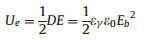
Generally, energy density (Ue) of dielectric materials could be calculated from equation Ue = ∫EdD [17], where E is the applied electrical field, and D is electrical displacement. With regard to linear dielectric materials (D-E loops can be seen in curve 2 in Fig. 1), such as BOPP, Ue could be derived from the following equation [18].
|

|
Download:
|
| Fig. 1. Schematic representation of unipolar electrical displacement-electric field (D-E) loops of linear dielectric (red line) and non-linear dielectric (blue line) materials. D: electric displacement, E: electrical field. Curve1 and 3 showthe charge and discharge pathway of non-linear dielectric materials, respectively. (For interpretation of the references to colour in this figure legend, the reader is referred to the web version of this article.) | |
where εγ is vacuum permittivity (8.85 × 10⁻¹² F/m), εγ and Eb are the permittivity and the breakdown strength of dielectric materials, respectively. As a consequence, increasing Eb is more effective than enhancing the dielectric constant of dielectric materials for elevating Ue. For non-linear dielectric materials, such as PVDF and its copolymers, dielectric response in D-E loops is tortuous (see curves 1 and 3 in Fig. 1).
As shown in Fig. 1, Ue has to be calculated from the integration of the blue area and the red area displays the unreleased energy, which is usually treated as energy loss (Ul). Therefore, suppressing he proportion of Ul is one of the directions to improve the performance of these ferroelectric materials.
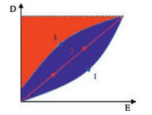
Prior to understanding several strategies of improving dielectric properties of polymer materials, various types of dielectric polarization [19] has to be fully illustrated. As shown in Fig. 2 [19], five types of polarization could be divided into two regimes including relaxation regime and resonance regime. Firstly, electronic polarization and atomic polarization appear at very high frequencies suggesting electron cloud and skeletal atom deviation around the position of equilibrium is rather fast [18]. Most of materials including polymers are able to generate these two polarizations. In addition, for polar polymers or polymers containing permanent dipoles, electric field would induce dipoles rotation associated with the dipolar polarization. This relaxation appears at a range of 10Hz to a few GHz depending on the crystalline or amorphous structure, temperature, and the polarity of the dipoles [18]. If impurity ions or ions exist in polymer materials, an ionic polarization would appear at frequency below a few hundred Hz. Finally, the interfacial polarization could be observed in multicomponent polymer materials ascribed to the Maxwell-Wagner effect [19]. As shown in Fig. 2, the large permittivity is always accompanied with the high dielectric loss. Therefore, interfacial and ionic polarizations are not desired for electric energy storage applications. Meanwhile, atomic and electronic polarizations would response quickly in rather wide frequency range, therefore, tailoring dipole polarization is themost promising strategy of optimizing dielectric properties of polymers for energy storage capacitors operating at frequency ranging from several to thousands Hz.

|
Download:
|
| Fig. 2. Five types of polarization in polymers: Pint: interfacial polarization; Pion: ionic polarization; Pdip: dipolar polarization; Pvib: vibrational (or atomic) polarization; Pe: electronic polarization. The upper panel reveals the realpartof permittivity (ε'), and the under panel shows the imaginary part of permittivity (ε*). Copied with permission [19]. Copyright 2014, American Chemical Society. | |
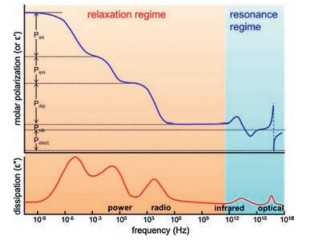
Among the known polymers, poly(vinylidene fluoride) (PVDF) [20-23], its copolymers [24-28] and terpolymers [29-31] are the most typical ferroelectric polymers possessing high permittivity and breakdown strength, which makes them promising candidates to manufacture high energy density materials. Different from the other ferroelectric materials such as ceramics, the polymorphs and corresponding conformation of PVDFare playing dominant roles in tailoring the dielectric properties of PVDF-based polymers. The constitutional formula of corresponding abbreviations are shown in Scheme 1.

|
Download:
|
| Scheme 1. The structural formula of polymers mentioned in this review. | |
2. Polymorphs and conformation of PVDF
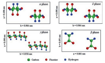
Normally, PVDF is polymerized from 1, 1-difluoroethylene (VDF) by free radical polymerization in emulsion or suspension. Due to the small size of fluorine atoms and its vinylidene structure [32], PVDF is semi-crystallized with a crystallinity of 50%-60% because of its structure defects [18]. As shown in Fig. 3, PVDF has four common crystal structures (α, β, γ and δ). Among them, the α phase is non-polar and the other three phases are polar. As shown in Fig. 3, the conformation and unit cells of α and δ forms are consistentbutthe dipolemoments arestackedin the oppositeway, which leads to their varied polarities. Generally, α-PVDF could be gained by slowly cooling from polymer melt [32]. By poling the α form PVDF under an electric field of 100-200MV/m, δ-PVDF could be obtained [33-35]. γ-Form PVDF could be achieved by solutioncast PVDF in polar solvents at temperature below 100 ℃ [34, 36] or annealing the melted films at high temperature [35, 37]. By mechanically stretching or poling α or γ form samples under high field of 400-500MV/m, β-PVDF could be fabricated [33].

|
Download:
|
| Fig. 3. Schematic illustrations of unit cells of four phases of PVDF. | |
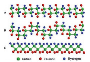
Three chain conformations of PVDF are commonly detected during crystallization, as listed in Fig. 4, including TGTG' (corresponding to α and δ form PVDF), TTTGTTTG' (referring to γ-PVDF), and TTTT (correlating to β-PVDF) (Tand G stand for trans and gauche conformation of VDF units, respectively). The dipole moments in both TGTG' and TTTGTTTG' conformations are parallel to the chain axis. However, in the all-trans conformation, dipole moments are perpendicular to the chain axis, which is responsible for its much bigger dipole moment than the other two conformations [18, 32]. Therefore, β form possesses the highest spontaneous polarization.

|
Download:
|
| Fig. 4. Schematic illustrations of chain conformations for (A) TGTG' (α/δ), (B) TTTGTTTG' (γ), and (C) all-trans (β) rotational sequences. | |
3. Relaxor ferroelectric behaviors of PVDF-based polymers
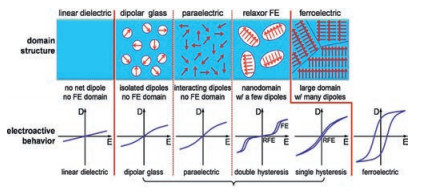
Polymer dielectrics are divided into several different types according to their domain structure, as shown in Fig. 5 by Lei Zhu [19]. For linear dielectric polymers, such as poly(propylene) (PP) and poly(ethylene terephthalate) (PET), their D-E loops are linear characterized with linearly increased displacement against electric field for the absence of polar groups and relatively low permittivity. For polymers containing dipoles, four distinct types of polymer would be achieved by varying the amount of dipoles and/or the size of domains. If dipoles are finely isolated into nonpolar linear dielectric polymers, dipolar glass could be obtained because the interactions between dipoles and between dipoles and matrix are weak. That is commonly seen in ceramics but barely found in polymers [19].

|
Download:
|
| Fig. 5. Different dipole and FE domain structures with increased dipole-dipole or domain-domain interactions from left to right (the top panel) and corresponding electroactive responses in D-E loops (the bottom panel). Copied with permission [19]. Copyright 2014, American Chemical Society. | |
As the amount of dipoles increasing, paraelectric (PE) structure with relatively strong interactions between dipole-matrix and dipole-dipole might be formed but no domain structure is built. PE behavior could be achieved by poling poly(vinylidene fluoride-cotrifluoroethylene) (P(VDF-TrFE)) at a high frequency (~1 kHz) [38]. For both dipole glass and PE structure, slim D-E loops could be observed in Fig. 5 for the quick response of dipole flipping along the electric field. Besides, ferroelectric(FE) behavior could be detected in PVDF [20, 21, 39, 40], PVDF based copolymers [41-43], and oddnumbered nylons [19] which possess a structure with large domain and a great number of dipoles. Upon polarization, dipoles in FE domain would be polarized under high electric field. However, when the electric field was removed, the oriented dipoles in normal ferroelectrics could not reverse due to the large coupling forces among aligned domains. As a consequence, the corresponding D-E loops are broad rectangular revealing a high hysteresis loss, which is undesirable for electrical energy storage applications.
Since the relaxor ferroelectric behavior was firstly reported by Qiming Zhang [44] in electron-irradiated poly(vinylidene fluoridetrifluoroethylene) copolymer, it has drawn great interest [29-32, 45-52] during past decades due to its great potential in energy storage applications. The relaxor ferroelectric behavior could be divided into two categories covering double hysteresis loop (DHL) and single hysteresis loop (SHL). As depicted in Fig. 5, polymer dielectrics showing double hysteresis possess higher discharge efficiency comparing with polymer dielectrics possessing single hysteresis, which is more desirable for energy storage applications.
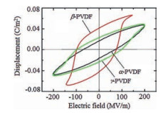
3.1. PVDF-based copolymersSince PVDF possesses relatively high dielectric constant (~12), which is rather important to achieve high Ue, PVDF films with different crystal forms (α, β, γ) are fabricated for energy storage [53]. As shown in Fig. 6, early polarization saturation is found in β-PVDF under low electric field and rather low Ue and Eb would be detected. α-PVDF and γ-PVDF exhibit slimmer D-E loops than β-PVDF, where α-PVDF possessing α lower remnant polarization than γ-PVDF. α-PVDF would be transferred into γ-PVDF under elevated electric field (over 300 MV/m). As a consequence, only γ-PVDF with mild polarity could be survived under high DC electric field with a Ue over 12 J/cm3.

|
Download:
|
| Fig. 6. (Color online) D-E hysteresis loops of PVDF in different crystal phases measured under AC electric field. (α-and β-PVDF films are quenched samples, and γ-PVDF film is uniaxially stretched. Copied with permission [53]. Copyright 2010, American Institute of Physics. | |
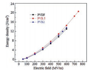
To modify the properties of PVDF, a series of monomers, such as trifluoroethylene (TrFE) [54, 55], chlorotrifluoroethylene (CTFE) [24, 56], and hexafluoropropylene (HFP) [23, 27] were utilized to copolymerize with VDF. The insertion of CTFE and HFP bearing large steric bulk would lead to the depressed crystallinity and melting temperature but stabilized a-form crystal in the resultant copolymer. Even stretching the P(VDF-CTFE) and P(VDF-HFP) films at low temperature, which has been widely utilized to transfer α-PVDF into β-PVDF [42, 57], could not change the crystal form. Uniaxially orientation of P(VDF-CTFE) and P(VDF-HFP) results into the significantly elevated Eb (over 700 MV/m) and very high Ue (> 25 J/cm3). As a matter of fact, either fabrication processes or conditions could barely vary the crystal forms in these copolymers [27, 58]. Recently, bromotrifluoroethylene (BTFE) was utilized to copolymerize with VDF as well [25, 26]. Because of the reactivity ratios of P(VDF-BTFE) are rVDF = 0.43 and rBTFE = 1.46 at 80 ℃ [32], some defects may be generated in both crystalline and amorphous phase, which in turn causes a molecular dependent conformation and stabilized γ phase depending onto particular BTFE content [25]. As shown in Fig. 7, the discharged energy density of PVB.5 is 20.8 J/cm3 at field of 750 MV/m. Comparing with the discharge energy densities of PVDF and PVB2 below 14 J/cm3, an improvement above 48% is achieved by introducing 0.5 mol% BTFE into PVDF. The elevated permittivity and breakdown strength of PVB.5 may account for the improvement of energy density. Interestingly, the PVB.5 copolymer possesses high γ phase content. These results show a new strategy to tailor the dielectric properties of PVDFbased polymers.

|
Download:
|
| Fig. 7. Discharge energy density of PVDF, PVB.5 (0.5 mol% BTFE), and PVB2 (2 mol% BTFE) as a function of applied field. Copied with permission [25]. Copyright 2014, American Chemical Society. | |
TrFE and CTFE are the monomers that capable of co-crystallizing with VDF units and are responsible for the stabilized β-form crystal [59]. However, the larger steric bulk of both monomers than VDF leads to the enlarged inter-chain distance with respect to PVDF homopolymers [19]. Thus, a weaken inter-chain reciprocity is induced, which in turn causes a lower Tc (Curie) transition temperature comparing with β phase PVDF homopolymer [32]. At temperature below Tc, the copolymer is in ferroelectric phase, and is transferred into paraelectric phase when the temperature is over Tc. Tc is the energy barrier that the frozen all-trans chain conformation has to overcome before the PVDF polymer chain segments could rotate freely jointed by TrFE. More TrFEs result into the shorted PVDF segments chopped by TrFE and the reduced energy barrier. As a consequence, Tc of P(VDF-TrFE) copolymers is reduced from 135 ℃ to 60 ℃ as the molecular content of TrFE increases from 20% to 50% [60]. However, these polymers still exhibit a normal ferroelectric behavior at room temperature. After exposed the P(VDF-TrFE) films to the high-energy electron beam, the size of all-trans conformation regions in P(VDF-TrFE) could be further pinned [61, 62]. An electron beam-irradiated P(VDF&HIPHEN; co-TrFE) having 50 mol% TrFE was firstly reported to show relaxor ferroelectric behavior [44]. It is thought that the chemical pinning created by irradiation cuts the crystals into small domains, which favors the reversibility of dipoles and is responsible for the relaxor ferroelectric behavior [47]. Nevertheless, the specific mechanism is still difficult to disclose because of the cross-linking structure [63]. Besides, the high energy radiation causes serious damage on the mechanical performance of the films as well, which is responsible for the rather low Eb thus small Ue observed in the resultant films. In addition, mechanical stretching and crosslinking are effective ways to simultaneously enhance the dielectric constant and breakdown strength along with suppressing the dielectric loss of PVDF copolymers [64, 65]. The crosslinking network may decrease the crystal size and the difficulty of dipolar switching during discharge, which results into suppressed dielectric loss [65].
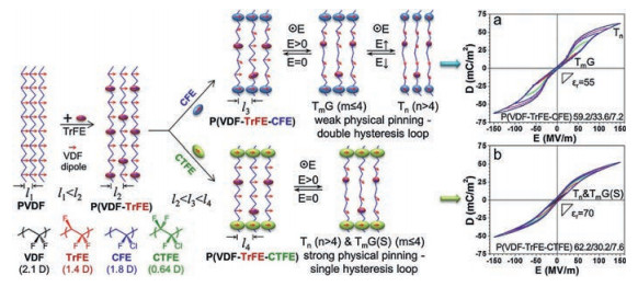
3.2. PVDF-based terpolymersBesides the radiation, the bulky defect could be introduced by inserting the third monomers to minimize the large remnant polarization of P(VDF-TrFE) copolymers [29, 30, 47]. The key to realize relaxor ferroelectric performance is the formation of nanosized ferroelectric domains and the effective pinning of dipoles [63]. The size of third monomer has to be restrictedly controlled to realize the pinning effect [19]. Normally, CTFE or 1, 1-chlorofluoroethylene (CFE) was chosen as the third monomer. As shown in Fig. 8, D-E loops of both P(VDF-TrFE-CFE) and P(VDF-TrFE-CTFE) with optimized composition exhibit fine relaxor ferroelectric profile. However, as the dipole moment and steric bulk of CFE and CTFE are different, different relaxor ferroelectric behaviors are observed. For P(VDF-TrFE-CFE), due to the smaller bulk and larger dipole moment of CFE, the physical pinning effect is weak, which induces the DHL profile in P(VDF-TrFE-CFE). On the other hand, CTFE has a larger size and smaller dipole moment. As a consequence, P(VDF-TrFE-CTFE) possesses a strong physical pinning effect showing a slim SHL [19].

|
Download:
|
| Fig. 8. Schematics of nanodomain formation in P(VDF-TrFE-CFE) 59.2/33.6/7.2 and P(VDF-TrFE-CTFE) 62.2/30.2/7.6. The right panel shows the resultant DHL and RFE behaviors (the poling frequency is 10 Hz with a triangular wave function). Copied with permission [30]. Copyright 2014, American Chemical Society. | |
Recently, some results show that P(VDF-TrFE-CTFE) terpolymers are able to exhibit normal ferroelectric, DHL, and SHL behaviors [29]. Physical pinning of defect size is not the only reason of determining the ferroelectric behaviors. It reveals that the DHL behavior is induced by many TG conformations developed in relaxor ferroelectric domains. On the other hand, SHL behavior could be achieved by the physically stretching procedure as well, which in turn breaks up the large blocks into small domains dispersed into crystals [29].
As shown in Fig. 9, D-E loops of P(VDF-TrFE-CTFE) (78.1/16.5/ 5.4 mol%) terpolymer with different processing methods were exhibited. TerSCAn and TerSCAnS samples show slimmer D-E loops than other four samples because the annealing process may accelerate the formation of α form, which is favorable for energy charge and discharge. Comparing with the unstretched samples, the stretched samples exhibit slimmer D-E loops with higher energy storage efficiency. After stretching, the large domains in paraelectric-like regions were broken into small domains [29], which would reduce the pinning effect on dipole rotation. These results reveal that both the third monomer size and the crystal structure may determine the ferroelectric behavior of PVDF-based terpolymers.

|
Download:
|
| Fig. 9. High field D/E loops of (a) TerQ, (b) TerAC, (c) TerSCAn, (d) TerQS, (e) TerACS, and (f) TerSCAnS. TerQ, TerAC, and TerSCAn are applied at a field up to 200 MV/m with the stretched versions shown up to 300 MV/m due to differences in breakdown strength. All measurements were carried out at 10 Hz (Samples of quenched, air cooled, and slow cooled and annealed from melt were named as TerQ, TerAC, and TerSCAn, respectively. Then uniaxially stretched samples were labeled as TerQS, TerACS, and TerSCAnS). Copied with permission [29]. Copyright 2015, American Chemical Society. | |
Besides the direct copolymerization of VDF and TrFE monomers, P(VDF-TrFE) based ferroelectric polymers could be synthesized from the controlled hydrogenation of P(VDF-CTFE) copolymers as well [54, 56, 66, 67]. The different VDF-TrFE connection series are responsible for the varied dielectric performances of P(VDF-TrFE) based copolymers with the consistent chemical compositions [68]. Their dielectric, ferroelectric and piezoelectric performances have been systematically investigated by varying the compositions and fabrication conditions [69-71]. Recently, more clean and environmental friend strategies have been developed for this hydrogenation process [72, 73]. With the lower TrFE content (no more than 20 mol%), the ferro-and piezo-electric performances of P(VDF-TrFE) synthesized from hydrogenation and direct copolymerization processes are rather close.
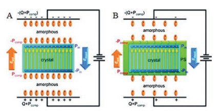
3.3. PVDF-Based grafted polymersAmong twotypes of relaxor ferroelectric behaviors, DHLbehavior is a good candidate for its high charge-discharge efficiency. Recently, based on an assumption [74] that a fast dipole reorientation could be achievedby reducing the compensation polarization, a DHLbehavior was achieved by grafting polystyrene (PS) onto the side chain of P (VDF-TrFE-CTFE) terpolymer [45, 46, 75]. A simple serial capacitor model [76] was utilized to explain this behavior. Normally, dipoles of amorphous and crystalline will be polarized under external electric field. As shown in Fig. 10, the orientation of dipoles of crystalline phase produces a polarization, Pin, which is compensated by Pcomp (polarization of amorphous phase). A local depolarization field (Edepol = Pin/ε0, where ε0 is vacuum permittivity) is created by Pin. In addition, another polarization field, Epol = (Pcomp + Q)/ε0 = (Pcomp + ε0E)/ε0 (where Q is the vacuum polarization), is produced by electrical displacement on the electrodes. Under dynamic external electric field, the competition between Epol and Edepol determines the ferroelectric behavior of PVDF-based polymers [18]. If Epol > Edepol, oriented dipoles are not able to switch back, resulting a high remnant polarization. Otherwise, part of oriented dipoles could return to its original direction, causing a DHL behavior. After grafting PS onto the side chain of P(VDF-TrFE-CTFE) terpolymer, the nanoscale P(VDF-TrFE) crystals were surrounded by PS-rich interfacial layer possessing a low polarizability. As a consequence, the compensation polarization was significantly reduced and a DHL behavior was observed [45].

|
Download:
|
| Fig. 10. Schematic models of polarization mechanisms for (A) P(VDF-TrFE) and (B) P (VDF-TrFE-CTFE)-g-PS. Note that after PVDF crystallization the grafted PS side chains form a nanoscale interfacial layer (green color) around the ferroelectric crystal (blue color). Copied with permission [45]. Copyright 2011, American Chemical Society. | |
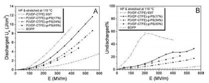
Fangxiao Guan et al. [46] graft PS onto the side chain of P(VDFCTFE) copolymer, and the discharged energy density and unreleased energy density of the objective copolymers are shown in Fig. 11. As presented in Fig. 11A, P(VDF-CTFE)-g-PS could be operated under higher electric field than P(VDF-CTFE). The discharged energy density of P(VDF-CTFE)-g-PS (17%) is slightly lower than that of P(VDF-CTFE) under the same field, but the maximum discharged energy density of P(VDF-CTFE)-g-PS (17%) is much higher than that of P(VDF-CTFE) for the significantly elevated breakdown strength. In addition, P(VDF-CTFE)-g-PSs exhibit much lower unreleased energy density than P(VDF-CTFE) as suggested in Fig. 11B. That indicates the grafting method is able to remarkably suppress the dielectric loss of P(VDF-CTFE), which is favorable for energy storage applications.

|
Download:
|
| Fig. 11. A) Discharged Ue, and B) undischarged% as a function of electric field for the hot-pressed and stretched films of P(VDF-CTFE) 93/7 and P(VDF-CTFE)-g-PS graft copolymers with different PS contents. The discharged Ue and undischarged-% for a commercial BOPP capacitor film are also included for comparison. Copied with permission [46]. Copyright 2011, WILEY-VCH Verlag GmbH & Co. KGaA, Weinheim. | |
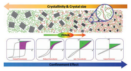
Different from PS grafted PVDF-based fluoropolymer, poly (methacrylate ester)s (PXMA, X = methyl, ethyl, and butyl) shows great miscibility with PVDF main, which allows them to finely tune both the crystal form of PVDF and the modulus in amorphous phase [78]. Using ATRP process, PXMA could be finely attached onto P(VDF-TrFE) main chain by grafting onto process. The significantly improved modulus in amorphous phase and the great confinement effect of PXMA on the flipping of ferroelectric domains are responsible for the continuously transferred ferroelectric behavior of P(VDF-TrFE) from normal ferroelectric to relaxor ferroelectric, anti-ferroelectric and even linear dielectrics, as illustrated in Fig. 12. The depressed ferroelectric relaxation by PXMA may address the ferroelectric transition and the improved Eb and Ue in the resultant copolymer. Most strikingly, the energy loss is reduced to as low as 16%, which is the lowest in these ferroelectric polymers [77, 79-82]. However, it is still double of BOPP and the significant temperature rising induced by the energy loss would lead to the early failure of the films and capacitors fabricated from these materials, which is the major obstacle and still the open challenge for PVDF based ferroelectric polymers to be utilized as energy storage capacitors.

|
Download:
|
| Fig. 12. Schematic illustrations of the microstructure and D-E hysteresis behaviors for different types of ferroelectrics. The black and green lines represent crystalline and amorphous PVDF molecular chains, respectively. The red lines represent the introduced PXMA side chains in an amorphous domain. Copied with permission [77]. Copyright 2013, the Royal Society of Chemistry. | |
4. Multilayer PVDF-based polymers
Apart from chemical modification of PVDF-based polymers, another approach to achieve high energy density and low dielectric loss materials is designing the interface/interphase to optimize the energy storage properties of multilayer polymer dielectrics [10, 83-90]. Although relaxor ferroelectric polymers show a slim D-E loops due to its development of nanodomains by means of the crystal pinning effect [19, 47], their low Curie transition temperature (Tc) and low melt point (~120 ℃) may seriously limit their applications under high temperature circumstances [10]. Another method to achieve high energy density and low dielectric loss polymers is to graft PVDF-based copolymers with polystyrene [45, 46, 75] or poly (methyl methacrylate) [77, 79, 80] on the side chains. Nevertheless, these approaches could hardly expand the production of the polymers for the limitation of polymerization method and the high cost [63, 91].
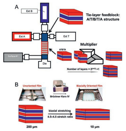
Recently, Case Western Reserve University reported a way to process multilayer polymer nanostructures using forced assembly technique (layer-multiplying coextrusion) [92]. This method is capable of producing films with layers from three to thousands with the layer thickness ranging from micro to nanosize. The apparatus of this technique is shown in Fig. 13A [10]. Due to the low conductivity and low dielectric loss properties of paraelectric polymers, such as polycarbonate (PC) [83, 84, 86-89, 93], polysulfone (PSF) [90], and poly(polyethylene glycol terephthalate) (PET) [10, 85], these polymers are used to fabricate multilayer films with PVDF or PVDF copolymers. By utilizing this technique, several disadvantages of PVDF-based polymers, such as high dielectric loss, are expected be inhibited due to the nano-confinement of the layered structure and interfaces [84].

|
Download:
|
| Fig. 13. Schematics of (A) three-component multilayer film coextrusion process via the forced assembly technique and (B) biaxial orientation of multilayer films using a Brückner Karo Ⅳ laboratory stretcher (film structure is not drawn to scale). Copied with permission [10]. Copyright 2016, American Chemical Society. | |
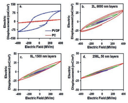
Firstly, the dielectric loss could be reduced. As shown in Fig. 14, D-E loops of PVDF are rectangular. After forced co-extrusion of PVDF with PC, D-E loops of multilayer films become slimmer than PVDF, which could be explained by the confined ion transportation in nanolayer structure [84]. For unipolar polymers, ionic mobility is lower than polar polymers. As a consequence, the PC layer in PC/ PVDF multilayer films could notably prevent the ion transferring. As suggested by Fig. 14, as the number of layer increases and the thickness of layer decreases, the hysteresis loss is reduced and nearly becomes negligible when the thickness of PVDF layer is less than 50 nm. Therefore, cutting down layer thickness of PVDF layer in multilayer polymer dielectrics is an effective way to reduce ion conduction loss.

|
Download:
|
| Fig. 14. D-E hysteresis loops of monolithic controls and 50PC/50PVDF layered films with different layer thicknesses. Key: (a) monolithic PC and PVDF controls, 12 μm thick; (b) 2 layers (12 μm/6000 nm); (c) 8 layers (12 μm/1500 nm); (d) 256 layers (12 μm/50 nm). Each loop at a given electric field has two poling cycles. For parts b-d, blue, magenta, green, and red loops correspond to the poling field being 100, 200, 300, and 400 MV/m, respectively. Copied with permission [84]. Copyright 2012, American Chemical Society. | |
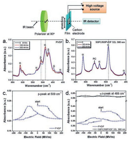
In addition, orientation polarization of crystalline phase in PVDF-based polymers could be avoided. As the large dielectric constant contrast between PVDF-based polymers and linear polymers, PVDF or PVDF copolymers layers with high permittivity possess a low nominal electric field while the linear polymer layers with low dielectric constant have a high electric field [93]. As a consequence, the low electric field will not be able to switch the dipoles of crystalline phase of PVDF-based polymers, but could switch the dipoles in amorphous phase. This hypothesis is demonstrated by Matthew Mackey using polarized FTIR method [84]. As shown in Fig. 15, both α and β phase could be observed in the stretched PVDF film. However, only α phase is found in the stretched PC/PVDF multilayer film, which means that PC/PVDF multilayer films possess the reduced dielectric loss due to the high dielectric loss of β phase. In addition, as revealed in Fig. 15c and d, under a bipolar electric field, peak intensities of both α and β phase of PVDF exhibit butterfly feature, suggesting the dipole reorientation of FE domains in PVDF film. On the contrary, little change in absorbance could be detected in α/δ-peak of PC/PVDF multilayer film, indicating no FE switching in PC/PVDF multilayer film under bipolar electric field.

|
Download:
|
| Fig. 15. Polarized FTIR spectra of uniaxially oriented (a) PVDF and (b) 50 PC/50PVDF (12 μm/380 nm) films under different electric fields. The polarized light is perpendicular to the film stretching direction (see the top panel for the polarized FTIR experimental setup). (c) The β-peak absorbance at 509 cm-1 and (d) the α/δ-peak absorbance at 488 cm-1 as a function of electrical field for uniaxially oriented PVDF and 50 PC/50PVDF (12 μm/380 nm) films. Copied with permission [84]. Copyright 2012, American Chemical Society. | |
Apart from the advantages as mentioned above, the multilayered films possess higher breakdown strength than monolithic PVDF-based polymers by designing the structure of multilayer films [88]. That could be ascribed to the interfacial polarization at the interfaces between PVDF and the linear polymers such as PC and PSF [90]. When the thickness of PSF is thick enough, interfacial charges created by electric poling could serve as effective charge traps for injected electrons from the metal electrodes [90]. In addition, the interfaces between linear polymers and PVDF are able to weaken the propagation of electrons, which could enhance the dielectric breakdown strength of multilayers. Besides, considering the breakdown strength of linear polymers is higher than PVDFbased polymers, the breakdown strength of monolithic PVDFbased polymers could be improved.
For both multilayer polymer films and polymer nanocomposites, one common issue is how to design the interface/interphase, which plays an important role of determining the property of materials. For both of the linear polymers mentioned above, none of them possess a good compatibility with PVDF-based polymers. Recently, Kezhen Yin [10] used PMMA, which is completely miscible with PVDF, as the bounding interphase between PETand P (VDF-HFP) to research the dielectric properties of PET/PMMA/ P(VDF-HFP) multilayer films. The procedure of preparing the multilayer films are presented in Fig. 13B.
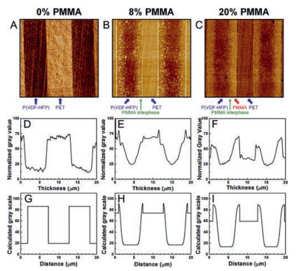
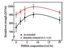
Fig. 16 shows the AFM phase images of PET/PMMA/P(VDF-HFP) multilayer films with different PMMA content. As shown in Fig. 16A, a sharp boundary between PET and P(VDF-HFP) could be detected. After introducing 8% PMMA into it, a diffused interphase region could be observed in Fig. 16B. Based on the experiment and simulation results from Fig. 16D-I, the multilayer films containing 8% PMMA have the best interphase, where PMMA is fully diffused in P(VDF-HFP). Furthermore, as shown in Fig. 17, PMMA could improve the dielectric strength of PET/P(VDF-HFP) multilayer films and the enhancing effect is the best when the PMMA content is 8%. For most commercial dielectric films, biaxial stretching is utilized to achieve thinner films and better energy storage properties. The biaxial orientation is used to further enhance the dielectric properties of multilayer films. These results could be ascribed to several reasons: 1) Biaxial orientation leads to the crystal of P(VDFHFP) oriented parallel to the layers, which restricts the dipole flipping along the chain axes, creating a barely αc relaxation, which in turn cut down the dielectric loss of αc; 2) Diffusion of PMMA in P (VDF-HFP) may suppress the immigration of impurity ions and injected charges; 3) The oriented PET crystal created by biaxial orientation may inhibit the chain movement of amorphous phase, which in turn enhances the breakdown strength of films [10, 86].

|
Download:
|
| Fig. 16. AFM phase images for PET/PMMA/P(VDF-HFP) multilayer films with (A) 0 vol%, (B) 8 vol%, and (C) 20 vol% PMMA tie layers. The images are 20 μm × 20 μm. (D-F) show experimentally measured gray values from the corresponding AFM images in A-C. (G-I) Calculated gray values for the films with 0, 8, and 20 vol% PMMA tie layers. Copied with permission [10]. Copyright 2016, American Chemical Society. | |

|
Download:
|
| Fig. 17. Dielectric breakdown strength (needle-plane geometry) as a function of PMMA tie layer composition for as-extruded PET/P(VDF-HFP) 33-layer films and biaxially oriented PET/PMMA/P(VDF-HFP) 65-layer films. Copied with permission [10]. Copyright 2016, American Chemical Society. | |
In general, dielectric polymeric films fabricated from PVDF based ferroelectric polymers show great advantages in high energy storage capabilities, which is highly desired in energy storage capacitors. However, the high energy loss induced by either the ferroelectric relaxation of ferroelectric domains or the leakage current is the major obstacle to overcome for the applications. So far, this is still an open question for the material scientists and more brilliant efforts are desperately requested to overcome the shortcoming of high loss.
5. ConclusionIn summary, high dielectric loss is the major treadstone of PVDF-based polymers for practical energy storage applications. In the past several decades, numerous researches have been conducted to achieving this goal while maintaining its high dielectric constant and breakdown strength. Relaxor ferroelectric polymer and multilayer films are good candidates for manufacturing high permittivity and low dielectric loss polymer films. For RFE polymer, DHL behavior is more favorable because of its lower dielectric loss comparing with SHL behavior. RFE behavior could be obtained by electron-irradiated, incorporating CFE or CTFE monomers onto P(VDF-TrFE), or grafting PS onto PVDF-based copolymer or terpolymer. However, the mechanisms of structureproperties are still not distinct. Several challenges, including high cost of grafting and large-scale production problem, restrict its practical application.
Another promising strategy for high energy density and low dielectric loss applications is multilayer PVDF-based polymers and linear polymer. By using multilayer coextrusion technology to designing the thickness and number of layer, several superior properties can be achieved. First, dielectric loss originating from dipoles reorientation in FE domains could be remarkably decreased because of the permittivity contrast between PVDFbased layer and linear polymer layer. In addition, dielectric loss from ion conduction is reduced by decreasing the thickness of PVDF layer. Moreover, breakdown strength could be improved due to the interfacial polarization in multilayer film. Furthermore, by designing the interface/interphase of PVDF-based multilayer films, their dielectric properties could be further improved.
In the future, more exploration is requested to be fulfilled to deeply disclose the mechanism of structure and property of PVDFbased polymers for high energy density and low loss application, especially for RFE polymers. Multilayer films show great potential for practical energy storage applications due to its feasibility of large-scale continuous production and great energy storage properties.
AcknowledgementsThe financial support from Special Fund of the National Priority Basic Research of China (No. 2014CB239503) and the National Natural Science Foundation of China (Nos. 51522703, 51477096) was acknowledged.
| [1] |
M. Yu, A. Wang, F. Tian, et al., Nanoscale 7(2015) 5292-5298. DOI:10.1039/C5NR00166H |
| [2] |
M. Yu, R. Li, Y. Tong, et al., J. Mater. Chem. A 3(2015) 9609-9615. DOI:10.1039/C5TA00651A |
| [3] |
X. Wang, G. Shi, Energy Environ. Sci. 8(2015) 790-823. DOI:10.1039/C4EE03685A |
| [4] |
Z. Zhao, M. Li, L. Zhang, L. Dai, Z. Xia, Adv. Mater. 27(2015) 6834-6840. DOI:10.1002/adma.201503211 |
| [5] |
S. Sengodan, S. Choi, A. Jun, et al., Nat. Mater. 14(2015) 205-209. DOI:10.1038/nmat4166 |
| [6] |
G. He, Z. Li, J. Zhao, et al., Adv. Mater. 27(2015) 5280-5295. DOI:10.1002/adma.201501406 |
| [7] |
V.V.T. Doan-Nguyen, S. Zhang, E.B. Trigg, et al., Acs Nano 9(2015) 8108-8115. DOI:10.1021/acsnano.5b02191 |
| [8] |
J. Ho, R. Ramprasad, S. Boggs, IEEE Trans. Dielectr. Electr. Insul. 14(2007) 1295-1301. DOI:10.1109/TDEI.2007.4339492 |
| [9] |
Q. Li, G. Zhang, F. Liu, et al., Energy Environ. Sci. 8(2015) 922-931. DOI:10.1039/C4EE02962C |
| [10] |
K. Yin, Z. Zhou, D.E. Schuele, et al., ACS Appl. Mater. Interfaces 8(2016) 13555-13566. DOI:10.1021/acsami.6b01287 |
| [11] |
X. Zhang, Y. Shen, B. Xu, et al., Adv. Mater. 28(2016) 2055-2061. DOI:10.1002/adma.201503881 |
| [12] |
Y. Xu, G. Shi, X. Duan, Acc. Chem. Res. 48(2015) 1066-1075. |
| [13] |
Q. Wu, Y. Xu, Z. Yao, A. Liu, G. Shi, Acs Nano 4(2010) 1963-1970. DOI:10.1021/nn1000035 |
| [14] |
K. Yuan, Y. Xu, J. Uihlein, et al., Adv. Mater. 27(2015) 6714-6721. DOI:10.1002/adma.201503390 |
| [15] |
H.W. Starkweather, P. Avakian, R.R. Matheson, J.J. Fontanella, M.C. Wintersgill, Macromolecules 25(1992) 6871-6875. DOI:10.1021/ma00051a023 |
| [16] |
T. Umemura, K. Akiyama, D. Couderc, IEEE Trans. Electr. Insul. EI-21(1986) 137-143. DOI:10.1109/TEI.1986.348936 |
| [17] |
Q. Wang, L. Zhu, J. Polym. Sci., Part B:Polym. Phys. 49(2011) 1421-1429. |
| [18] |
L. Zhu, Q. Wang, Macromolecules 45(2012) 2937-2954. DOI:10.1021/ma2024057 |
| [19] |
L. Zhu, J. Phys. Chem. Lett. 5(2014) 3677-3687. DOI:10.1021/jz501831q |
| [20] |
R. Gregorio, E.M. Ueno, J. Mater. Sci. 34(1999) 4489-4500. DOI:10.1023/A:1004689205706 |
| [21] |
J.Y. Lim, S.Y. Park, S. Kwak, H.J. Kim, Y. Seo, Polymer 97(2016) 465-471. DOI:10.1016/j.polymer.2016.05.055 |
| [22] |
Y.L.J. Claude, K. Li, Q. Wang, Chem. Mater. 20(2008) 2078-2080. DOI:10.1021/cm800160r |
| [23] |
F. Guan, J. Wang, J. Pan, Q. Wang, L. Zhu, Macromolecules 43(2010) 6739-6748. DOI:10.1021/ma101062j |
| [24] |
R. Han, J. Jin, P. Khanchaitit, J. Wang, Q. Wang, Polymer 53(2012) 1277-1281. DOI:10.1016/j.polymer.2012.02.004 |
| [25] |
M.R. Gadinski, K. Han, Q. Li, et al., ACS Appl. Mater. Interfaces 6(2014) 18981-18988. DOI:10.1021/am504874f |
| [26] |
M.R. Gadinski, C. Chanthad, K. Han, L. Dong, Q. Wang, Polym. Chem. 5(2014) 5957-5966. DOI:10.1039/C4PY00690A |
| [27] |
F. Guan, J. Pan, J. Wang, Q. Wang, L. Zhu, Macromolecules 43(2010) 384-392. DOI:10.1021/ma901921h |
| [28] |
X.Z. Chen, X. Li, X.S. Qian, et al., Polymer 54(2013) 2373-2381. DOI:10.1016/j.polymer.2013.02.041 |
| [29] |
M.R. Gadinski, Q. Li, G. Zhang, X. Zhang, Q. Wang, Macromolecules 48(2015) 2731-2739. DOI:10.1021/acs.macromol.5b00185 |
| [30] |
L. Yang, B.A. Tyburski, F.D. Dos Santos, et al., Macromolecules 47(2014) 8119-8125. DOI:10.1021/ma501852x |
| [31] |
B. Neese, S.G. Lu, B. Chu, Q.M. Zhang, Appl. Phys. Lett. 94(2009) 042910. DOI:10.1063/1.3077189 |
| [32] |
Q. Li, Q. Wang, Macromol. Chem. Phys. 227(2016) 1228-1244. |
| [33] |
A.J. Lovinger, Science 220(1983) 1115-1121. DOI:10.1126/science.220.4602.1115 |
| [34] |
F. Takeo, N. Kenji, K. Tomoyoshi, D. Munehiro, Jpn. J. Appl. Phys. 26(1987) 1039-1045. |
| [35] |
X. He, K. Yao, B.K. Gan, J. Appl. Phys. 97(2005) 084101. DOI:10.1063/1.1862323 |
| [36] |
Z. Cui, N.T. Hassankiadeh, Y. Zhuang, E. Drioli, Y.M. Lee, Prog. Polym. Sci. 51(2015) 94-126. DOI:10.1016/j.progpolymsci.2015.07.007 |
| [37] |
K. Nakagawa, Y. Ishida, J. Polym. Sci:Polym. Phys. Ed. 11(1973) 2153-2171. DOI:10.1002/pol.1973.170110908 |
| [38] |
R. Su, J.K. Tseng, M.S. Lu, et al., Polymer 53(2012) 728-739. DOI:10.1016/j.polymer.2012.01.001 |
| [39] |
T. Lu, A.J. Studer, D. Cortie, et al., ACS Appl. Mater. Interfaces 8(2016) 14313-14317. DOI:10.1021/acsami.6b02868 |
| [40] |
V.K. Prateek, R.K. Gupta Thakur, Chem. Rev. 116(2016) 4260-4317. DOI:10.1021/acs.chemrev.5b00495 |
| [41] |
Z.Y. Cheng, D. Olson, H. Xu, et al., Macromolecules 35(2002) 664-672. DOI:10.1021/ma0112265 |
| [42] |
X. Zhou, B. Chu, B. Neese, M. Lin, Q.M. Zhang, IEEE Trans. Dielectr. Electr. Insul. 14(2007) 1133-1138. DOI:10.1109/TDEI.2007.4339472 |
| [43] |
Y. Wang, X. Zhou, Q. Chen, B. Chu, Q. Zhang, IEEE Trans. Dielectr. Electr. Insul. 17(2010) 1036-1042. DOI:10.1109/TDEI.2010.5539672 |
| [44] |
Q.M. Zhang, V. Bharti, X. Zhao, Science 280(1998) 2101-2104. DOI:10.1126/science.280.5372.2101 |
| [45] |
F. Guan, J. Wang, L. Yang, et al., Macromolecules 44(2011) 2190-2199. DOI:10.1021/ma102910v |
| [46] |
F. Guan, L. Yang, J. Wang, et al., Adv. Funct. Mater. 21(2011) 3176-3188. DOI:10.1002/adfm.201002015 |
| [47] |
L. Yang, X. Li, E. Allahyarov, et al., Polymer 54(2013) 1709-1728. DOI:10.1016/j.polymer.2013.01.035 |
| [48] |
Q. Li, G. Zhang, X. Zhang, et al., Adv. Mater. 27(2015) 2236-2241. DOI:10.1002/adma.201405495 |
| [49] |
X. Qian, H.J. Ye, T. Yang, et al., Adv. Funct. Mater. 25(2015) 5134-5139. DOI:10.1002/adfm.v25.32 |
| [50] |
Q. Chen, Y. Shen, S. Zhang, Q.M. Zhang, Annu. Rev. Mater. Res. 45(2015) 433-458. DOI:10.1146/annurev-matsci-070214-021017 |
| [51] |
H.M. Bao, J.F. Song, J. Zhang, et al., Macromolecules 40(2007) 2371-2379. DOI:10.1021/ma062800l |
| [52] |
S. Zhang, B. Neese, K. Ren, B. Chu, Q.M. Zhang, J. Appl. Phys. 100(2006) 044113. DOI:10.1063/1.2335778 |
| [53] |
W. Li, Q. Meng, Y. Zheng, et al., Appl. Phys. Lett. 96(2010) 192905. DOI:10.1063/1.3428656 |
| [54] |
Y.Y. Lu, J. Claude, Q.M. Zhang, Q. Wang, Macromolecules 39(2006) 6962-6968. DOI:10.1021/ma061311i |
| [55] |
H. Xu, G. Shanthi, V. Bharti, Q.M. Zhang, T. Ramotowski, Macromolecules 33(2000) 4125-4131. DOI:10.1021/ma9919561 |
| [56] |
Y.Y. Lu, J. Claude, B. Neese, Q.M. Zhang, Q. Wang, J. Am. Chem. Soc. 126(2006) 8120-8121. |
| [57] |
X. Zhou, X. Zhao, Z. Suo, et al., Appl. Phys. Lett. 94(2009) 162901. DOI:10.1063/1.3123001 |
| [58] |
W. Xia, Z. Xu, F. Wen, W. Li, Z. Zhang, Appl. Phys. Lett. 97(2010) 222905. DOI:10.1063/1.3518921 |
| [59] |
Q. Li, K. Han, M.R. Gadinski, G. Zhang, Q. Wang, Adv. Mater. 26(2014) 6244-6249. DOI:10.1002/adma.201402106 |
| [60] |
K.J. Kim, G.B. Kim, C.L. Valencia, J.F. Rabolt, J. Polym. Sci. B Polym. Phys. 32(1994) 2435-2444. DOI:10.1002/polb.1994.090321501 |
| [61] |
B. Daudin, M. Dubus, J.F. Legrand, J. Appl. Phys. 62(1987) 994-997. DOI:10.1063/1.339685 |
| [62] |
A.J. Lovinger, Macromolecules 18(1985) 910-918. DOI:10.1021/ma00147a016 |
| [63] |
E. Baer, L. Zhu, Macromolecules 50(2017) 2239-2256. DOI:10.1021/acs.macromol.6b02669 |
| [64] |
S. Tan, X. Hu, S. Ding, et al., J. Mater. Chem. A 1(2013) 10353-10361. DOI:10.1039/c3ta11484h |
| [65] |
P. Khanchaitit, K. Han, M.R. Gadinski, Q. Li, Q. Wang, Nat. Commun. 4(2013) 2845. |
| [66] |
Z. Wang, Z. Zhang, T.C.M. Chung, Macromolecules 39(2006) 4268-4271. DOI:10.1021/ma060738m |
| [67] |
E. Liu, Z. Zhang, Acta Polymerica Sinica(2010), 1129-1135. |
| [68] |
Z. Zhang, Q. Meng, T.C.M. Chung, Polymer 50(2009) 707-715. DOI:10.1016/j.polymer.2008.11.005 |
| [69] |
W. Xia, Z. Xu, Q. Zhang, Z. Zhang, Y. Chen, J. Polym. Sci. B Polym. Phys. 50(2012) 1271-1276. DOI:10.1002/polb.23125 |
| [70] |
W. Xia, Q. Zhang, X. Wang, Z. Zhang, J. Appl. Polym. Sci. 131(2014) 40114. |
| [71] |
J. Wang, Z. Li, Y. Yan, et al., Chin. J. Polym. Sci. 34(2016) 649-658. DOI:10.1007/s10118-016-1782-8 |
| [72] |
S. Tan, E. Liu, Q. Zhang, Z. Zhang, Chem. Commun. 47(2011) 4544-4546. DOI:10.1039/c1cc00106j |
| [73] |
Z. Zhang, Z. Zhu, Xi'an Jiaotong University, China patent, ZL 201210086186. 8, 2012.
|
| [74] |
F. Guan, Z. Yuan, E.W. Shu, L. Zhu, Appl. Phys. Lett. 94(2009) 052907. DOI:10.1063/1.3079332 |
| [75] |
L. Yang, E. Allahyarov, F. Guan, L. Zhu, Macromolecules 46(2013) 9698-9711. DOI:10.1021/ma401660k |
| [76] |
C.T. Black, C. Farrell, T.J. Licata, Appl. Phys. Lett. 71(1997) 2041-2043. DOI:10.1063/1.119781 |
| [77] |
J. Li, X. Hu, G. Gao, et al., J. Mater. Chem. C 1(2013) 1111-1121. DOI:10.1039/C2TC00431C |
| [78] |
Q. Meng, W. Li, Y. Zheng, Z. Zhang, J. Appl. Polym. Sci. 116(2010) 2674-2684. |
| [79] |
J. Li, S. Tan, S. Ding, et al., J. Mater. Chem. 22(2012) 23468-23476. DOI:10.1039/c2jm35532a |
| [80] |
J. Li, H. Gong, Q. Yang, et al., Appl. Phys. Lett. 104(2014) 263901. DOI:10.1063/1.4886391 |
| [81] |
B. Miao, J. Liu, X. Zhang, et al., RSC Adv. 6(2016) 84426-84438. DOI:10.1039/C6RA17977K |
| [82] |
H. Gong, B. Miao, X. Zhang, J. Lu, Z. Zhang, RSC Adv. 6(2016) 1589-1599. DOI:10.1039/C5RA22617A |
| [83] |
M. Mackey, D.E. Schuele, L. Zhu, E. Baer, J. Appl. Phys. 111(2012) 113702. DOI:10.1063/1.4722348 |
| [84] |
M. Mackey, D.E. Schuele, L. Zhu, et al., Macromolecules 45(2012) 1954-1962. DOI:10.1021/ma202267r |
| [85] |
J.M. Carr, M. Mackey, L. Flandin, et al., J. Polym. Sci. Part B:Polym. Phys. 51(2013) 882-896. DOI:10.1002/polb.23277 |
| [86] |
Z. Zhou, J. Carr, M. Mackey, et al., J. Polym. Sci. Part B:Polym. Phys. 51(2013) 978-991. DOI:10.1002/polb.23296 |
| [87] |
M.A. Wolak, M.J. Pan, A. Wan, et al., Appl. Phys. Lett. 92(2008) 113301. DOI:10.1063/1.2897029 |
| [88] |
M. Mackey, A. Hiltner, E. Baer, et al., J. Phys. D Appl. Phys. 42(2009) 175304. DOI:10.1088/0022-3727/42/17/175304 |
| [89] |
Z. Zhou, M. Mackey, J. Carr, et al., J. Polym. Sci. Part B:Polym. Phys. 50(2012) 993-1003. DOI:10.1002/polb.v50.14 |
| [90] |
J.K. Tseng, S. Tang, Z. Zhou, et al., Polymer 55(2014) 8-14. DOI:10.1016/j.polymer.2013.11.042 |
| [91] |
G. Zhang, D. Brannum, D. Dong, et al., Chem. Mater. 28(2016) 4646-4660. DOI:10.1021/acs.chemmater.6b01383 |
| [92] |
M. Ponting, A. Hiltner, E. Baer, Macromol. Symp. 294(2010) 19-32. DOI:10.1002/masy.v294:1 |
| [93] |
M.H. Lean, M.A. Wolak, M. Mackey, E. Baer, IEEE Trans. Dielectr. Electr. Insul. 21(2014) 800-808. DOI:10.1109/TDEI.2013.004119 |