 2017, Vol. 28


In recent years, amounts of heavy metal wastewater have been produced in metallurgy, electroplating, chemical engineering, mining and metal machining industries, and threatened human health and ecosystem seriously [1]. For the purpose of removing heavy metal contaminant from aquatic system, pioneers carried out many beneficial explorations, including coagulation, flotation, biological treatment, chemical precipitation, membrane osmosis, evaporation and adsorption [2, 3]. Among these methods, adsorbent is a significant choice for its high efficiency, easy operating, renewability and favorable selectivity [4]. Srivastava and Majumder [5] found ion exchange resin adsorbent could remove toxic metal ions (Cu (Ⅱ), As (Ⅲ), Pb (Ⅱ)) out of wastewater efficiently. Shafaei et al. [6] adopted activated carbon prepared by eucalyptus bark to adsorb Cu (Ⅱ) and Pb (Ⅱ), whose maximum adsorbance could reach 0.45 mmol g-1 and 0.53 mmol g-1 respectively. Sangvanich et al. [7] discovered that modified regular mesoporous material had adsorption selectivity for Cu (Ⅱ), Cs (Ⅰ) and Tl (Ⅰ).
Chitosan is a unique natural alkalescent polysaccharide synthesized by chitin hydrolyzing and deacetylation at alkalescent condition [8]. There are plentiful amino functional groups which are able to chelate metal ions on molecular chain of chitosan with complicated double helix structure [9]. According to Gamage and Shahidi [10], the biopolymer chitosan presented an excellent capability of removing metal ion pollutant of Pb (Ⅱ), Cu (Ⅱ), Zn (Ⅱ) and so on. Chitosan, a natural macromolecule material regarded as a metal ion absorbent, has attracted much attention due to its extensive sources, nontoxicity, biocompatiblity and degradability [11, 12]. For the convenient recovery and separation, chitosan was prepared as microsphere or particle generally. Besides, chitosan in itself can carry out various reactions with other substances, which makes it an ideal material for graft modification so as to improve its adsorption performance. Zhou et al. [13] used ethylenediamine as modification agent, and prepared ethylenediamine-modified magnetic crosslinking chitosan microspheres for adsorption of Hg (Ⅱ). Fujiwara et al. [14] synthesized crosslinked chitosan which was chemically modified with L-lysine to investigate the adsorption of Pt (Ⅳ), Pd (Ⅱ) and Au (Ⅲ) from aqueous solutions. In addition, glutaraldehyde, thiourea, rubeanic acid and epichlorohydrin all could be employed for graft modification [15-17].
Microfluidic technology, a facile microsphere synthesis approach, points out a new direction in producing functional material of controllable size, morphology, component and structure [18]. Some researchers have developed various chitosan microspheres via microfluidic method. Xu et al. explored uniform and high monodispersed spherical particles which were applied in catalysis, biomedical sciences and medicine field [19-21]. Besides, they also prepared composite chitosan/silica microspheres used in adsorption [22]. Lu et al. [23] synthesized Pb (Ⅱ) imprinted chitosan (Pb (Ⅱ)-CS) bead with uniform size and porous morphology for selective adsorption of Pb (Ⅱ). However, there are few attempts to combine microfluidic technology with graft modification in preparing chitosan microspheres of high performance used in environment protection field. The situation does not permit any delay of exploring the potential benefits of utilizing microfluidic synthesized material in heavy metals treatment. The present work was aimed at exploiting a biosorbent of thiourea modified chitosan microspheres (TMCM) with high specific surface area as a model adsorption material for heavy metal. TMCM were prepared by a combination of facial microfluidic technology with nature adsorbent of chitosan. Through droplets forming, chemical crosslinking and pores creating, chitosan microspheres with high specific surface area were obtained. Then on this basis, amounts of amino functional group were grafted on chitosan through thiourea modification. In final, stoving was considered as a fast and efficient method to dry this biosorbent for the enhancement of mechanical property and peculiar surface structure. The adsorption behavior of TMCM toward copper (Ⅱ) had been investigated by batch experiments. TMCM exhibited higher adsorption capacity (qe=60.6 mg g-1) and faster adsorption rate than that nonmodified chitosan microsphere (NMCM). The adsorption kinetic was described well by the pseudo-second order kinetic model.
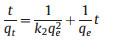
2. Results and discussion 2.1. Characteristic researches 2.1.1. SEM analysisDroplets solidifying 30 min appeared golden yellow, which was different from that solidifying 5 min remarkably under an optical microscope, as shown in Fig. 1(a and b). These droplets were uniform and high monodispersed, which profited from the distinct feature of microfluidic technology in product control. After organic solvent cleaning and washing by deionized water, great changes have taken place.

|
Download:
|
| Figure 1. Optical micrographs of droplets for (a) solidifying 5 min, (b) 30 min and (c) after cleaning and washing. | |
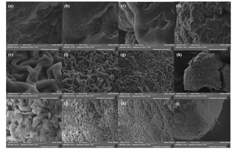
A more meticulous observation with SEM is shown in Fig. 2. Fig. 2(a-d) and (e-h) shows the surface of NMCM whose mass ratio between PEG and chitosan was 1:1 and 2:1, respectively. Through SEM images, we found that there was an obvious difference on the surface of NMCM when mass ratio between PEG and chitosan changed. When mass ratio between PEG and chitosan was 1:1, the surface of NMCM represented wrinkling, whose situation was as like as ravines and gullies criss-cross. In the valley bottom, there were pieces of fish scale. The morphology was so different from normal chitosan microspheres without PEG added in prepared by microfluidic technology, whose surface was highly smooth and spherical as seen in Fig. 3. When mass ratio between PEG and chitosan was 2:1, the situation on the surface of NMCM changed again. There were lots of curly strips which tangled together. Amounts of pores and spaces were produced on the surface, which increased the specific surface area greatly. Microspheres with high specific surface area would be beneficial for fast adsorption. Therefore, we adopted microspheres whose mass ratio between PEG and chitosan was 2:1 to make graft modification by thiourea. Fig. 2(i-l) shows the SEM images of TMCM. We found that the surface of TMCM was similar to that of NMCM. Besides, the curly strips on the surface seemed more compact. The pores and spaces became narrow and small. This phenomenon may be caused by the modification process. In the graft modification, reactions between microspheres and external agents occurred continuously. Reaction products and the state variation of microspheres would cause some differences with the comparison to NMCM. In order to verify the high specific surface area of TMCM, we adopted Brunauer-Emmett-Teller (BET) and Barrett-Joyner-Halenda (BJH) methods to analyze specific surface area and pore volume of TMCM and NMCM. The specific surface area and pore volume of TMCM were 69.2 m2 g-1 and 0.023 cm3 g-1, while that of NMCM (w (PEG):w (CS)=0:1) were 4.24 m2 g-1 and 0.0011 cm3 g-1. The specific surface area of TMCM increased greatly and it was beneficial for fast adsorption.

|
Download:
|
| Figure 2. SEM graphs of NMCM (a-d) when w (PEG):w (CS)=1:1 and (e-h) w (PEG):w (CS)=2:1, and (i-l) TMCM when w (PEG):w (CS)=2:1 at 30, 000×, 10, 000×, 5000×, 1000×, respectively. | |
2.1.2. Preparation process
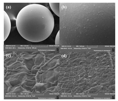
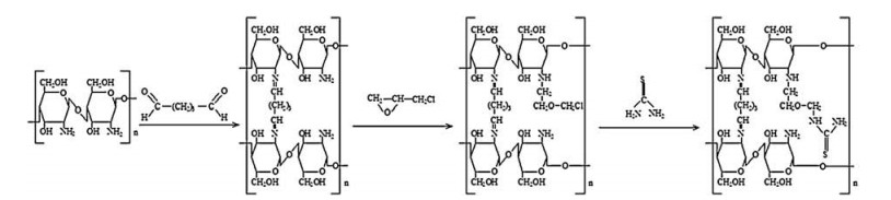
The peculiar surface structure of NMCM could be explained by the specific preparation process. PEG was added in chitosan solution as pore-foaming agent. In the microfluidic chip, uniform droplets with controllable component of PEG and chitosan were produced. Then, these droplets were led into a beaker filled with solidification bath for crosslinking. In the process of crosslinking, the chain structure of chitosan molecule previously turned into network structure on account of Schiff-base reaction as shown in Fig. 3. Unsolidified microspheres were fragile and easy to polymerizate together. After solidification, microspheres became compact and stable. When microspheres were taken out solidification bath, they would be cleaned by n-octane, acetone and ethanol in turn for the elimination of unreacted glutaraldehyde and maintaining the existence of PEG. Then, microspheres were washed by deionized water for several times. PEG, as a porefoaming agent, was easily dissolved in water. After organic solvents cleaning, PEG was preserved in microspheres. When washed by deionized water, PEG would dissolve in water quickly, but the network structure of chitosan still kept original state. Many pores could be left in microspheres. The absence of component resulted in the bone of microsphere instable.

|
Download:
|
| Figure 3. SEM graphs of (a, b) NMCM when w (PEG):w (CS)=0:1 at 400× and 1000×, and (c, d) the interior structure at 30, 000× and 10, 000×. | |
When drying, these pores would shrink, and the instable bone also had a tendency to frap. Finally, NMCM with peculiar surface structure were prepared. In the formation process, the mass ratio between PEG and chitosan played an important role. More PEG was added in chitosan solution, more pores would be left in microspheres, which caused the bone more instable. The surface of NMCM would have more possibilities when drying. But the droplets would fail to form microspheres after drying when too much PEG was added in chitosan solution. It was attributable to that the bone of microsphere would be no longer in existence after the disappearance of PEG. In conclusion, we considered that the mass ratio between PEG and chitosan being 2:1 was suitable for preparing microspheres with high specific surface area. Fig. 4 shows the formation process of microspheres with high specific surface area.

|
Download:
|
| Figure 4. The formation process of microspheres with high specific surface area. | |
2.1.3. FTIR analysis
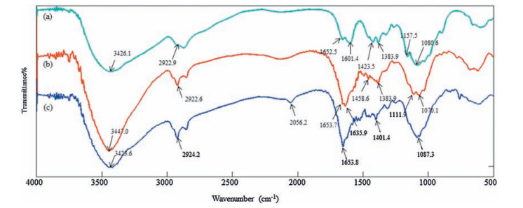
Fig. 5(a) shows the FTIR spectrum of chitosan powder. The absorption peak around 3426.1 cm-1 was due to the stretching vibrations of -OH, -NH and intermolecular hydrogen bonding [24]. The adsorption peak around 1080.6 cm-1 corresponded with the stretching vibration of C-O in primary and secondary hydroxyl group [25, 26]. 2920.6 cm-1 was the stretching vibration absorption peaks of C-H [27]. 1601.4 cm-1 was the characteristic adsorption peak of amides [28].

|
Download:
|
| Figure 5. FTIR spectrums of (a) chitosan powder, (b) NMCM and (c) TMCM. | |
Fig. 5(b) shows the FTIR spectrum of NMCM, whose integral position of absorption peaks altered little, with the exception of at 1635.9 cm-1 where a new peak appeared on account of shrinking vibration of C=N [29]. It suggested that crosslinking had occurred successfully based on Schiff-base reaction between -CHO of glutaraldehyde and -NH2 of chitosan. The Schiff-base reaction process between chitosan and glutaraldehyde is shown in Scheme 1. When solidification bath contacted with microspheres, glutaraldehyde would spread into microspheres from it and permeated from surface to interior gradually. Therefore, crosslinking action also took place on the surface first and then in the inside. Through solidification, microsphere became compact, stable and elastic.

|
Download:
|
| Scheme 1. Schematic depiction of the formation of TMCM. | |
Fig. 5(c) shows the FTIR spectrum of TMCM. In this FTIR spectrum, there were some differences when compared with the FTIR spectrum of NMCM. 1401.4 cm-1 was considered as the characteristic adsorption peak of -S=C-N < group. In addition, there was a small amount of~NH2 · HSCN groups at 2056.2 cm-1 [30]. Thus, successful modification was indicated by the appearances of -S=C-N < group and~NH2 · HSCN group. The schematic depiction of synthesis process was described in Scheme 1 [31].
2.1.4. EDS analysisFig. 6 shows EDS spectrums of NMCM and TMCM, where elements had changed greatly. In the EDS spectrum of NMCM, carbon, nitrogen and oxygen occupied subtotal proportion (96.41%), owing to the molecular structural composition of chitosan. But in the EDS spectrum of TMCM, the contents of sulfur and nitrogen increased largely, which could be caused by graft modification. Thiourea modification provided amounts of sulfur on TMCM. Besides, according to schematic deception of modification process, nitrogen in products would be three times more than that in materials theoretically. In consideration of uncomplete reaction, the EDS results indicated that most thiourea had been grafted on NMCM successfully. For the increase of chlorine, it may be attributable to the existence of reaction intermediates.

|
Download:
|
| Figure 6. EDS spectrums of (a) NMCM and (b) TMCM. | |
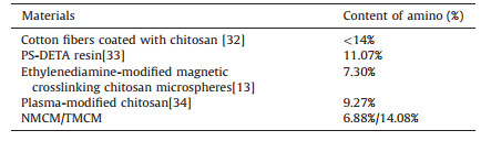
The content of amino of NMCM and TMCM was determined by linear titration method, whose results were 6.88% and 14.08%, respectively. Compared to NMCM, there were more amino existing on TMCM and the adsorption capacity of TMCM was improved largely. The contents of amino of other materials which had been reported were listed in Table 1. From the table, we found that TMCM was superior to others in terms of the content of amino. The graft modification was achieved successfully and the results were also consistent with EDS analysis.
|
|
Table 1 EDS spectrums of (a) NMCM and (b) TMCM. |
2.1.5. Mechanical strength
A successful absorbent also needs sufficient mechanical strength excepting for high adsorption capacity, fast adsorption rate and environmental friendliness, so as to protect absorbent form breaking when resisting various forces in the application process. Stoving is beneficial for the enhancement of mechanical properties and the formation of peculiar surface structure. The variations of average diameter and mechanical strength of microspheres as drying time increased were shown in Fig. 7. Microspheres contained so much water at the first stage of drying and liquid microspheres were unable to resist extruding. With the drying time increasing, water decreased gradually which made microspheres flexible and had ability to oppose deformation when suffering various external forces. Mechanical strength improved. This was the reason for high mechanical after drying for 2.5 h at this stage. Microspheres became smaller due to the dehydration. When water evaporated completely, extreme solid microsphere became so brittle to break straightly without plastic deformation at the moment of suffering force in a certain extent. Mechanical strength reduced to a low level again at the final stage, which was different form the first stage absolutely. Fig. 7(a) illustrated the schematic diagram of mechanical strength test, which showed different microspheres before and after fracture.

|
Download:
|
| Figure 7. (a) Schematic diagram of mechanical strength test and (b) mechanical strength with drying time. | |
2.2. Effect factors of microspheres forming
In process of droplets forming, we found viscosity and flow speed ratio between dispersed phase and continuous phase had influence on microsphere morphology and size. Dispersed phase could resist shear force for the viscosity of itself. Hence, higher weight percent of chitosan in dispersed phase resulted in lager viscosity and bigger resistance for a harder droplet forming, which asked us to adjust the viscosity and flow speed ratio of liquid. With the increased dispersed phase viscosity in the scope of shearing, droplet diameter and dried microsphere size also increased which contributed to that larger viscosity would lead to the time extension of dispersed phase necking, drawing and forming a bigger droplet after breaking. Flow speed ratio affected microspheres size apparently, and it was reasonable to consider that the decrease of microspheres size was relevant to the increase of flow speed ratio in a certain range. The times of continuous phase shearing dispersed phase in unit time would increase as continuous phase flow speed improved while dispersed phase flow speed remained invariable, which gave rise to the reduction of droplet size. Fig. 8 shows the influences of viscosity and flow speed ratio on microsphere diameter.

|
Download:
|
| Figure 8. The influence of (a) viscosity and (b) flow ratio on microsphere diameter. (c) The droplet forming process at cross aisle. | |
We also realized the position of sheering in microfluidic chip affected microspheres uniformity greatly. Shearing taking place in cross aisle could guarantee microsphere holistic uniformity due to the limitation of channel size at the moment of droplet forming, which was the most optimal result. Fig. 8(c) shows the forming process of droplet at cross aisle. If shearing takes place in intersection or flow channel, droplet size will act randomly when dispersed phase breaks into a droplet, which gets the probability of irregular microsphere increasing without the limitation of channel size. Channel size limited droplets to form regularly and flow speed ratio affected microsphere diameter, which ranged microsphere size broadly from 400 μm to 1500 μm. Microfluidic technology exhibited its advantages in preparing microsphere of controllable, stable and variable size.
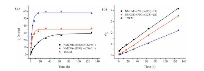
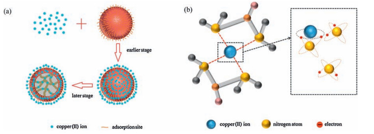
2.3. Adsorption experimentsFig. 9(a) exhibited the typical adsorption kinetics of three different chitosan microspheres. They showed different adsorption capacity and equilibrium time though they had the same trend in adsorption process. In their adsorption processes, adsorption action developed fast at the earlier stage according to the slope of curve and then became flat gradually, which could be explained that adsorption acted on the surface of microspheres at first, and the process of copper ions arrived at surface from solution was quick. Adsorption sites on the surface provided place for copper (Ⅱ) ions to land on. Then, copper (Ⅱ) ions infiltrated into the interior of microspheres from the surface to go on chelating with functional groups, which was slower than the previous stage. The number of adsorption sites on the surface of microspheres decided the adsorption rate mostly, so microspheres with high specific surface area could reach equilibrium more quickly. Even though three different chitosan microspheres showed the same trend in adsorption process, their adsorption capacity had large difference. TMCM exhibited larger adsorption capacity than others, which profited from the increase of amino functional groups through graft modification. Fig. 10(a) shows the process of copper (Ⅱ) ions adsorption.
|
(1) |
|
(2) |

|
Download:
|
| Figure 9. (a) The typical adsorption kinetic curves and (b) the fitting curves of pseudo-second order model. (C0=100 mg L-1, pH=5.5, T=303 K) Pseudo-first and pseudo-second order model as following were employed to fit with the adsorption kinetic curve. | |

|
Download:
|
| Figure 10. (a) The process of copper (Ⅱ) ions adsorption and (b) the situation of chelating copper (Ⅱ) ion. | |
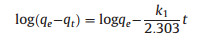
where qe and qt are the adsorption capacity at equilibrium and at time t. K1 is the rate constant of pseudo-first order model and k2 is the rate constant of pseudo-second order model. The value of calculated adsorption capacity, rate constant and correlation coefficient (R2) are determined from slope and intercept of plots log (qe -qt) versus t and t/qt versus t.
The fitting parameters of different chitosan microspheres for two kinetic models were summarized in table 2. all chitosan microspheres were suitable for pseudo-second order model. fig. 9(b) shows fitting curves of pseudo-second order model. their adsorption equation correlation coefficients (r2) were larger than that of pseudo-first order model. their fitting degrees of pseudosecond order model were far better than that of pseudo-first order model since their adsorption equation correlation coefficient (r2) were much larger than that of pseudo-first order model. besides, the calculated adsorption capacities of pseudo-second order model were so close to the experimental adsorption capacities.
|
|
Table 2 The fitting parameters of pseudo-first and pseudo-second order model. |

pseudo-second order model assumes that adsorption rate is decided by the square value of unoccupied adsorption sites on the surface of sorbent and adsorption process is controlled by chemical adsorption mechanism. Therefore, chemical adsorption occupied a leading position in adsorption process. These factors suggested that our copper (Ⅱ) adsorption was more aligned with the second order adsorption kinetic and absorbing copper (Ⅱ) on chitosan microspheres was chemical adsorption due to the influence of chemical bond along with electrons transferring in a significant degree. Lone pairs of electrons provided by nitrogen atoms of amino were thrown into empty track of copper (Ⅱ) ions to achieve adsorption through forming coordination bonding. Fig. 10(b) shows the situation of chelating copper (Ⅱ) ion. It was also believed that physical adsorption on account of Van der Waals force and electrostatic force was less relative to our adsorption rate. Microspheres with high specific surface area and more functional groups would provide more adsorption sites and have stronger capacity. This could be explained for fast adsorption rate and high adsorption capacity of TMCM. Table 3 lists some adsorbents derived from chitosan for copper (Ⅱ), in which we find that TMCM has large advantages to adsorb copper (Ⅱ). Although the adsorption mechanism is bound to be different for each adsorbent, it is our hope that a basic understanding will lead to a further exploration of chitosan microspheres in the adsorption process of heavy metal.
|
|
Table 3 The adsorption capacity of different sorbents for copper (Ⅱ). |

3. Conclusion
For the purpose of removing heavy metal out wastewater, chitosan microspheres with high specific surface area and adsorption capacity were prepared as a model sorbent through microfluidic technology. Thiourea was chosen as suitable modification agent for the increase of amino functional groups. PEG played an important role in the formation of different surface structures. For the enhancement of mechanical property, stoving was used as a fast and efficient method to dry them. The SEM, FTIR and EDS results indicated that thiourea had been grafted on chitosan microspheres successfully. Copper (Ⅱ) was employed to test the adsorption performance of TMCM. The experimental results showed that TMCM had higher adsorption capacity (qe=60.6 mg g-1) and faster adsorption rate than NMCM. The adsorption kinetic was described well by the pseudo-second order kinetic model. The adsorption mechanism toward copper (Ⅱ) also had been clarified, which suggested that chemical adsorption along with electrons transferring was dominant in adsorption process. All these researches provide a brand new direction for preparing high performance sorbent used in heavy metals treatment via microfluidic technology.
4. Experimental 4.1. MaterialsDeacetylated chitosan (85%) (Aladdin Industrial Co., Ltd., Shanghai, China) was dissolved in acetic acid glacial (Tianlian Chemical Technology Co., Ltd., Shanghai, China) to form an aqueous solution with polyethylene glycol (Reagent Co., Ltd., Shanghai, China) added in, which served as dispersed phase. The solution was stirred in thermostat water bath (HWCL-3, GreatWall, China) until it became clarified and non-sparkling. A surfactant, Span 80 (Reagent Co., Ltd., Shanghai, China) was added into continuous phase to protect chitosan droplets from polymerizing. The continuous phase was n-octane (Lingfeng Chemical Co., Ltd., Shanghai, China) with Span 80 added in. Glutaraldehyde (Lingfeng Chemical Co., Ltd., Shanghai, China) was utilized as crosslinking reagent for solidification. Thiourea was considered as an excellent choice for graft modification. Epichlorohydrin, acetone, ethanol, CuCl2·2H2O and other reagents utilized in this work were all A.R. grade reagents and used as received. Deionized water was used throughout the experiments.
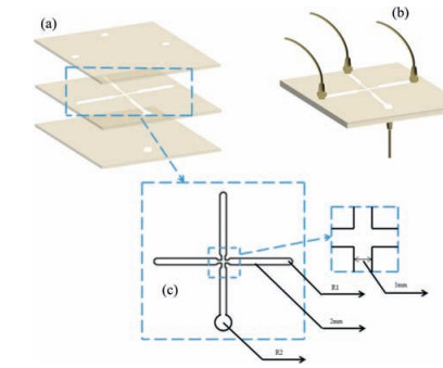
4.2. Microfluidic system design and fabricationAs shown in Fig. 11(a and b), the microfluidic chip was fabricated by three pieces of polymethyl methacrylate (PMMA) plates from top to bottom. The top plate (50 × 50 × 1) mm3 had three same holes of 2 mm in diameter. Two holes were continuous phase inlets and the other hole was dispersed phase inlet. The middle plate (50 × 50 × 1) mm3 was carved with two orthogonal and absolute penetrable channels which were 40 mm in length and 2 mm in width by laser engraving machine (VLS2.30, Universal, America). At the cross aisle, channels shrank to 1 mm in width and 3 mm in length because of fluid shear condition and the necessity of microsphere diameter limitation. The channels of middle plate are shown in Fig. 11(c). The bottom plate (50 × 50 × 1) mm3 contained a hole of 3 mm in diameter which was larger than inlet holes in order to be beneficial for formed droplets outflowing. Three PMMA plates were sealed via hot compression molding. Teflon tubes' orifices were stuck to inlet holes and outlet hole. The other orifices were connected with injected pump. Dispersed phase was pumped into the microfluidic chip through a singlechannel injected pump (Longer, LSP02-1A, China). Meanwhile, continuous phase was pumped to shear dispersed phase through a double-channel injected pump (Longer, LSP02-1B, China) at the cross aisle. When droplets formed, they flowed out of chip and were led into a beaker which contained solidification bath for crosslinking.

|
Download:
|
| Figure 11. Schematic drawing of the microfluidic chip (a) the chip in expanded view, (b) the chip in assembly view and (c) the middle plate channels view. | |
4.3. Preparation of TMCM
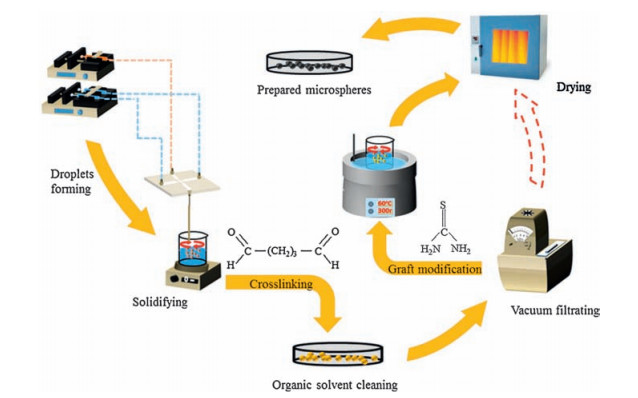
An aqueous solution which contained 4.0 wt% chitosan dissolved by 2.0 wt% acetic acid and a certain amount of polyethylene glycol (PEG) was used as dispersed phase. 2.0 wt% Span 80 which was used as surfactant and viscosity modifier was mixed with 98 wt% n-octane to prepare continuous phase. The solidification bath was n-octane solution with 0.5 wt% glutaraldehyde and 2 wt% Span80 added in. Continuous phase was pumped into microfluidic chip to sheer dispersed phase at the cross aisle. Dispersed phase necked first under extrusion and shear force, and then it drew and broke into a spherical microsphere finally for its own surface tension. The microsphere flowed through outlet steadily and uniformly into a beaker filled with solidification bath for crosslinking on magnetic stirrer (Yuezhong, ZNCL-S-10D, China). Microspheres received a standard solidification treatment, comprising a two-step solidification process, first getting droplets for 5 min and second stirring for a period, both along with crosslinking. Crosslinked microspheres were cleaned by n-octane, acetone and ethanol in turn. Then, microspheres were washed by deionized water through vacuum filtrating for several times. After above steps, 10.0 wt% microspheres were put into acetone solution containing 2.0 wt% thiourea and 1.0 wt% epichlorohydrin, which was stirred in a thermostat water bath at 60 ℃ for 5 h. Finally, after drying at 50 ℃ in an oven (Heyi, DHG-9023A, China), TMCM were prepared. Non-modified chitosan microspheres (NMCM) were also prepared without graft modification of thiourea. The flow chart of preparing TMCM is shown in Fig. 12.

|
Download:
|
| Figure 12. The flow chart of preparing TMCM. | |
4.4. Characteristics of TMCM
The droplets which were solidified and washed by deionized water were observed through an optical microscope (AZ100, Nikon, Japan) and the formation process in microfluidic chip was recorded by an on-line CCD (C-FLED2, Nikon, Japan). The surface and morphology of TMCM and NMCM were observed particularly through a scanning electron microscope (SEM) (S3400N, HITACHI, Japan). Fourier transformed infrared (FTIR) (Nicolet 6700, Thermo Fisher, America) was employed to detect functional group transition. Energy dispersive spectrometer (EDS) was also used to measure the variation of elements between TMCM and NMCM. For mechanical strength test, we adopted a self-made method of using strength test machine (HPA, Handpi, China) to measure twelve microspheres' strength values at the moment microsphere fractured. After removing the maximum and minimum values, the average value was taken as the mechanical strength.
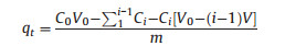
4.5. Adsorption experimentWhen CuCl2·2H2O crystal dissolved into deionized water, there formed a certain concentration CuCl2 aqueous solution. A certain amount of microspheres were added into CuCl2 aqueous solution, which were kept stirring at 300r min-1 speed on a shaking table (SPH-304, Shiping, China) at constant temperature. A pipette was used to extract quantitative supernatant liquid of phials each time at certain interval which was determined according to empirical data in pilot experiments. The concentration of supernatant liquid was detected through an inductively coupled plasma optical emission spectrometer (Agilent ICP-725ES, Agilent Techologies, America). Absorbance at certain interval was calculated with the equation as following:
|
(3) |
where C0 is the initial concentration of copper and Ci is the concentration of copper at time ti. V0 is the initial volume of solution and V is the volume of extracted supernatant liquid. M is the weight of adsorbents used in experiment.
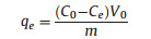
Adsorption capacity was determined with the equation as following.
|
(4) |
where C0 is the initial concentration of copper and Ce is the equilibrium concentration of copper. V0 is the initial volume of solution. M is the weight of adsorbents used in experiment.
AcknowledgmentsWe acknowledge the support by National Basic Research Program of China (No. 2014CB748500) and National Natural Science Foundation of China (Nos. 51578239, 51322805).
| [1] | J.J. Cheng, G.R. Shan, P.J. Pan, Temperature and pH-dependent swelling and copper (Ⅱ) adsorption of poly (N-isopropylacrylamide) copolymer hydrogel. RSC Adv. 5 (2015) 62091–62100. DOI:10.1039/C5RA09965J |
| [2] | S.Y. Zhu, H.Y. Guo, F.F. Yang, Z.S. Wang, Thiacalix[4] arene 1, 2, 3-triazole-polyethylene glycol polymers:synthesis and dye adsorption properties. Chin. Chem. Lett. 26 (2015) 1091–1095. DOI:10.1016/j.cclet.2015.03.031 |
| [3] | Z. Al-Qodah, Biosorption of heavy metal ions from aqueous solutions by activated sludge. Desalination 196 (2006) 164–176. DOI:10.1016/j.desal.2005.12.012 |
| [4] | S. Noor, M. Waseem, U. Rashid, Fabrication of NiO coated SiO2 and SiO2 coated NiO for the removal of Pb2+ ions. Chin. Chem. Lett. 25 (2014) 819–822. DOI:10.1016/j.cclet.2014.01.040 |
| [5] | N.K. Srivastava, C.B. Majumder, Novel biofiltration methods for the treatment of heavy metals from industrial wastewater. J. Hazard. Mater. 151 (2008) 1–8. DOI:10.1016/j.jhazmat.2007.09.101 |
| [6] | A. Shafaei, M. Rezayee, M. Arami, M. Nikazar, Removal of Mn2+ ions from synthetic wastewater by electrocoagulation process. Desalination 260 (2010) 23–28. DOI:10.1016/j.desal.2010.05.006 |
| [7] | T. Sangvanich, V. Sukwarotwat, R.J. Wiacek, Selective capture of cesium and thallium from natural waters and simulated wastes with copper ferrocyanide functionalized mesoporous silica. J. Hazard. Mater. 182 (2010) 225–231. DOI:10.1016/j.jhazmat.2010.06.019 |
| [8] | F.Y. Ding, H.B. Deng, Y.M. Du, X.W. Shi, Q. Wang, Emerging chitin and chitosan nano fibrous materials for biomedical applications. Nanoscale 6 (2014) 9477–9493. DOI:10.1039/C4NR02814G |
| [9] | I.M.N. Vold, K.M. Vårum, E. Guibal, O. Smidsrød, Binding of ions to chitosanselectivity studies. Carbohydr. Polym. 54 (2003) 471–477. DOI:10.1016/j.carbpol.2003.07.001 |
| [10] | A. Gamage, F. Shahidi, Use of chitosan for the removal of metal ion contaminants and proteins from water. Food Chem. 104 (2007) 989–996. DOI:10.1016/j.foodchem.2007.01.004 |
| [11] | G. Ke, W.C. Guan, C.Y. Tang, Covalent modification of multiwalled carbon nanotubes with a low molecular weight chitosan. Chin. Chem. Lett. 18 (2007) 361–364. DOI:10.1016/j.cclet.2007.01.010 |
| [12] | Y.M. Yang, W.J. Zhao, J.H. He, Nerve conduits based on immobilization of nerve growth factor onto modified chitosan by using genipin as a crosslinking agent. Eur. J. Pharm. Biopharm. 79 (2011) 519–525. DOI:10.1016/j.ejpb.2011.06.008 |
| [13] | L.M. Zhou, Z.R. Liu, J.H. Liu, Q.Q. Huang, Adsorption of Hg (Ⅱ) from aqueous solution by ethylenediamine-modified magnetic crosslinking chitosan microspheres. Desalination 258 (2010) 41–47. DOI:10.1016/j.desal.2010.03.051 |
| [14] | K. Fujiwara, A. Ramesh, T. Maki, H. Hasegawa, K. Ueda, Adsorption of platinum (Ⅳ), palladium (Ⅱ) and gold (Ⅲ) from aqueous solutions onto L-lysine modified crosslinked chitosan resin. J.Hazard. Mater. 146 (2007) 39–50. DOI:10.1016/j.jhazmat.2006.11.049 |
| [15] | E. Guibal, N.V.O. Sweeney, M.C. Zikan, T. Vincent, J.M. Tobin, Competitive sorption of platinum and palladium on chitosan derivatives. Int. J. Biol. Macromol. 28 (2001) 401–408. DOI:10.1016/S0141-8130(01)00130-1 |
| [16] | A.M. Donia, A.A. Atia, K.Z. Elwakeel, Selective separation of mercury (Ⅱ) using magnetic chitosan resin modified with Schiff's base derived from thiourea and glutaraldehyde. J. Hazard. Mater. 151 (2008) 372–379. DOI:10.1016/j.jhazmat.2007.05.083 |
| [17] | L.M. Zhou, J.P. Xu, X.Z. Liang, Z.R. Liu, Adsorption of platinum (Ⅳ) and palladium (Ⅱ) from aqueous solution by magnetic cross-linking chitosan nanoparticles modified with ethylenediamine. J. Hazard. Mater. 182 (2010) 518–524. DOI:10.1016/j.jhazmat.2010.06.062 |
| [18] | J.H. Kim, T.Y. Jeon, T.M. Choi, Droplet microfluidics for producing functional microparticles. Langmuir 30 (2014) 1473–1488. DOI:10.1021/la403220p |
| [19] | H. Zhao, J.H. Xu, T. Wang, G.S. Luo, A novel microfluidic approach for preparing chitosan-silica core-shell hybrid microspheres with controlled structures and their catalytic performance. Lab Chip 14 (2014) 1901–1906. DOI:10.1039/C4LC00079J |
| [20] | J.H. Xu, H. Zhao, W.J. Lan, G.S. Luo, A novel microfluidic approach for monodispersed chitosan microspheres with controllable structures. Adv. Healthc. Mater. 1 (2012) 106–111. DOI:10.1002/adhm.201100014 |
| [21] | H. Zhao, J.H. Xu, P.F. Dong, G.S. Luo, A novel microfluidic approach for monodispersed chitosan microspheres with enhanced autofluorescence. Chem. Eng. J. 215-216 (2013) 784–790. DOI:10.1016/j.cej.2012.10.063 |
| [22] | H. Zhao, J.H. Xu, W.J. Lan, T. Wang, G.S. Luo, Microfluidic production of porous chitosan/silica hybrid microspheres and its Cu (Ⅱ) adsorption performance. Chem. Eng. J. 229 (2013) 82–89. DOI:10.1016/j.cej.2013.05.093 |
| [23] | Y.C. Lu, J. He, G.S. Luo, An improved synthesis of chitosan bead for Pb (Ⅱ) adsorption. Chem. Eng. J. 226 (2013) 271–278. DOI:10.1016/j.cej.2013.04.078 |
| [24] | C.X. Li, J.M. Pan, J. Gao, Y.S. Yan, G.Q. Zhao, An ion-imprinted polymer supported by attapulgite with a chitosan incorporated sol-gel process for selective separation of Ce (Ⅲ). Chin. Chem. Lett. 20 (2009) 985–989. DOI:10.1016/j.cclet.2009.03.020 |
| [25] | R. Molina, P. Jovancic, S. Vilchez, T. Tzanov, C. Solans, In situ chitosan gelation initiated by atmospheric plasma treatment. Carbohydr. Polym. 103 (2014) 472–479. DOI:10.1016/j.carbpol.2013.12.084 |
| [26] | E. Guibal, C. Milot, O. Eterradossi, C. Gauffier, A. Domard, Study of molybdate ion sorption on chitosan gel beads by different spectrometric analyses. Int. J. Biol. Macromol. 24 (1999) 49–59. DOI:10.1016/S0141-8130(98)00067-1 |
| [27] | Y.M. Ren, X.Z. Wei, M.L. Zhang, Adsorption character for removal Cu (Ⅱ) by magnetic Cu (Ⅱ) ion imprinted composite adsorbent. J. Hazard. Mater. 158 (2008) 14–22. DOI:10.1016/j.jhazmat.2008.01.044 |
| [28] | H.T. Deng, J.J. Wang, M. Ma, Z.Y. Liu, F. Zheng, Hydrophobic surface modification of chitosan gels by stearyl for improving the activity of immobilized lipase. Chin. Chem. Lett. 20 (2009) 995–999. DOI:10.1016/j.cclet.2009.03.037 |
| [29] | Z.K. Wang, Q.L. Hu, Y.X. Wang, Preparation of chitosan rods with excellent mechanical properties:one candidate for bone fracture internal fixation. Sci. China Chem. 54 (2011) 380–384. |
| [30] | K.C. Gavilan, A.V. Pestov, H.M. Garcia, Mercury sorption on a thiocarbamoyl derivative of chitosan. J. Hazard. Mater. 165 (2009) 415–426. DOI:10.1016/j.jhazmat.2008.10.005 |
| [31] | L. Wang, R.E. Xing, S. Liu, Recovery of silver (Ⅰ) using a thiourea-modified chitosan resin. J. Hazard. Mater. 180 (2010) 577–582. DOI:10.1016/j.jhazmat.2010.04.072 |
| [32] | L.F. Zemljič, S. Strnad, O. Šauperl, K. Stana-Kleinschek, Characterization of amino groups for cotton fibers coated with chitosan. Text. Res. J. 79 (2009) 219–226. DOI:10.1177/0040517508093592 |
| [33] | L.Q. Yang, Y.F. Li, X.L. Jin, Synthesis and characterization of a series of chelating resins containing amino/imino-carboxyl groups and their adsorption behavior for lead in aqueous phase. Chem. Eng. J. 168 (2011) 115–124. DOI:10.1016/j.cej.2010.12.048 |
| [34] | A. Uygun, M. Kiristi, L. Oksuz, S. Manolache, S. Ulusoy, RF hydrazine plasma modification of chitosan for antibacterial activity and nanofiber applications. Carbohydr. Res. 346 (2011) 259–265. DOI:10.1016/j.carres.2010.11.020 |
| [35] | Y.C. Chang, D.H. Chen, Preparation and adsorption properties of monodisperse chitosan-bound Fe3O4 magnetic nanoparticles for removal of Cu (Ⅱ) ions. J. Colloid Interface Sci. 283 (2005) 446–451. DOI:10.1016/j.jcis.2004.09.010 |
| [36] | N. Li, R.B. Bai, Copper adsorption on chitosan-cellulose hydrogel beads:behaviors and mechanisms. Sep. Purif. Technol. 42 (2005) 237–247. DOI:10.1016/j.seppur.2004.08.002 |
| [37] | Y.M. Ren, M.L. Zhang, D. Zhao, Synthesis and properties of magnetic Cu (Ⅱ) ion imprinted composite adsorbent for selective removal of copper. Desalination 228 (2008) 135–149. DOI:10.1016/j.desal.2007.08.013 |