 2015, Vol.26


b Department of Chemistry, Shanghai Key Laboratory of Molecular Catalysis and Innovative Materials, Laboratory of Advanced Materials and Collaborative Innovation Center of Chemistry for Energy Materials, Fudan University, Shanghai 200433, China;
c Sinopec, China Petroleum & Chemical Corporation, Beijing 100027, China
Microporous zeolite and mesoporous materials are two families of inorganic porous matrix [1, 2, 3]. As we all known,mesoporous material refers to a particular kind of material with pore diameters between 2 nm and 50 nm [4]. Because of its large surface,low diffusion limit,excellent surface condensation ability [5, 6, 7, 8, 9, 10],the mesoporous material has great potential in adsorption processes, shape separation,high efficient catalysis and nano-equipment applications etc. [11, 12, 13, 14, 15, 16]. Compared to the simple mechanical mixture between micro- and meso-porous materials,the micro@- meso composite obtained from the chemical means could make their combination truly at nano-scale level [17]. In 2005,Yoon’s research group synthesized a silicalite-1@mesoporous core-shell structure with the help of n-octadecyltrimethoxysilane (C18-TMS) for the first time [18]. Although the outside mesoporous layer is not so uniformly dispersed,it was considered to be a new type of material with hierarchical pores distributed at the nano-scale. Since then,Ying et al. applied cetyltrimethylammonium bromide (CTAB) to fabricate the zeolite@mesoporous core-shell structures. They skillfully took advantage of the solubility of zeolite in alkaline solutions to release the silicon species as the growing source for the formation of outer mesopores [19]. Xu et al. also used CTAB as a template to produceTS-1@mesoporous after the modification of zeolite with poly(diallyldimethylammonium chloride) (PDDA). Following the adsorption of gold nano particles,this composite could perform well in the selective epoxidation reaction of propylene [20]. Recently,professor Zhao has developed a convenient way to led to a micro-meso-product of ZSM-5@SBA-15 with the P123 (PEO-PPO-PEO) as a template under acidic conditions [21] and explored it in menthol to propylene (MTP) reaction with fine catalytic performance. It could be concluded that the micro@meso core-shell structure has attracted more and more researchers due to its specific characters and structures. Another member in the mesoporous family is the porous carbon [22] with mesopores (2- 50 nm) inside. Owing to its peculiar features such as the resistance to the acid or the alkalinity,the flexibility of the pore size and the large surface area [23, 24, 25, 26],the mesoporous carbon has been widely used as an excellent support for the catalytic processes and electronic applications [27, 28, 29, 30].
As an inorganic core-shell structure,the zeolite microcapsule is synthesized through assembling strategies of nano-seeds via layer-by-layer fabrication methods [31]. It has been demonstrated that the zeolite microcapsule could be used as an effective catalyst both in tandem reactions of fine chemical syntheses and kinetic dynamic reactions in biochemistry owing to its shape selectivity, screening and isolation effects [[3TD$DIF]32,33]. The precise construction of zeolite microcapsules could not only provide the high-uniformity of dispersed Pt nanoparticles,the improved connectivity of mesoand micro-pores and the enlarged flexibility of the functionalization for its better performance in catalysis but also realize the integration of catalytic reactors in one composite. Our work mainly focused on the distinct modification of silicalite-1 microcapsule (denoted as S1) with interior meso-carbon and exterior mesopore, respectively,which enabled the possibility for second or even third modification of S1. Each functionalized S1 has been characterized in detail.
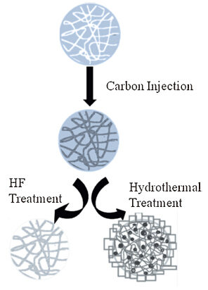
2. Experimental 2.1. The interior modification of S1 with meso-carbonThe mesoporous silica spheres (MSSs) were fabricated according to our previous work [32]. Then,0.5 g of MSSs was impregnated in sugar solutions with different concentrations and stirred at room temperature for 12 h. After heated to 100 ℃,this solution was kept stirring for 12 h and at 150 ℃ for 6 h. Finally,the solid products were collected by filtration and fully carbonized at 900 ℃ for 6 h under argon to obtain the MSSs with carbon inside (C-MSS). The samples of C-MSS-1,C-MSS-2 and C-MSS-3 were prepared with the sugar concentration at 20 wt%,40 wt% and 60 wt%, respectively. The above products were then added into an HF solution to remove the carbon template. After washing and drying, the samples of C-HSM-1,C-HSM-2 and C-HSM-3 were obtained respectively. We used C-MSS-2 as a representative for the hydrothermal treatment and modified its surface with the zeolite seeds as the literature indicated [32]. This seeded C-MSS-2 was then dropped into the precursor solution with a molar ratio ofTPABr:H2O:NaOH = 18:2000:0.2 and heated to 90 ℃ for 8 h. After cooling down to room temperature,the solids were collected by filtration and the interior carbonized S1 (C-HSM-4) was obtained by further washing with demineralized water and drying at the 80 ℃. The process for the carbonization was illustrated in Fig. 1.

|
Download:
|
| Fig.1. Schematic illustration of the formation of C-HSMs | |
0.5 g of MSSs was modified with an amine-group [32] and then dropped into the precursor containing both sugar (40 wt%) and HPtCl4 (3 wt%). The solution was heated to 100 ℃ and stirred for 12 h,and then to 150 ℃ for 6 h. The carbonization was conducted at 900 ℃ under argon and the MSSs with Pt and carbon inside (Pt- C-MSS) were obtained. After assembling the silicalite-1 seeds via the layer-by-layer method on the Pt-C-MSS,the seeded samples were added to the precursor solution as the procedure described in Section 2.1 and heated to 90 ℃ for 8 h. The hollow solids (Pt-CHSM) were collected by filtration and then washed and dried for further characterizations.
2.3. The outside modification of S1 with mesoporeUsing P123 as the template: To prepare the precursor for mesopore modification: 0.039 g of P123 was first dissolved in 20 mL of HCl,followed by the addition of 0.116 g of MgSO4 and 0.1 g of S1. After 30 min of ultrasonic treatment,0.05 g of TEOS was added slowly to the above solution and kept stirring for 24 h at room temperature. Then the solution was treated at 90 ℃ for 8 h and the modified zeolite microcapsules (S1@meso-1) were finally calcinated at 550 ℃ for 6 h to remove the organic template.
Using CTAB as the template: 0.1 g of the prepared S1 was added to a PDDA solution (0.3 wt%) and stirred for 30 min. After centrifugation,the solids were washed and dried,then dropped into a CTAB solution. Afterwards,0.3 g of ammonium hydroxide (28 wt%) was injected to adjust the acidity of the CTAB solution. Certain amount of TEOS was added drop wise to the solution with vigorous stirring,and the agitation was kept for 6 h after the addition. After treated at 90 ℃ for 8 h,the white solids were collected by filtration and the final S1@meso was obtained by washing,drying and calcinating at 550 ℃ for 6 h. The samples of S1@meso-2 and S1@meso-3 were prepared with the corresponding TEOS content at 5 wt% and 10 wt%,respectively.
2.4. CharacterizationThe solid products were characterized by powder X-ray diffraction (XRD) on an Rigaku D/max-IIA equipment with Cu Ka radiation for the determination of phase purity and crystallinity of the samples. It worked at the condition of 40 kV,40 mA with a scanning rate of 0.02°/min (2θ). Scanning Electron Microscopy (SEM) images were taken from anXL30E equipment of FEI Company. Transition electron microscopy (TEM) and energy dispersive spectrometer (EDS) were taken from a JEOL JEM-2010 equipment. Nitrogen adsorption and desorption data were obtained from a Micromeritics ASAP-2000.
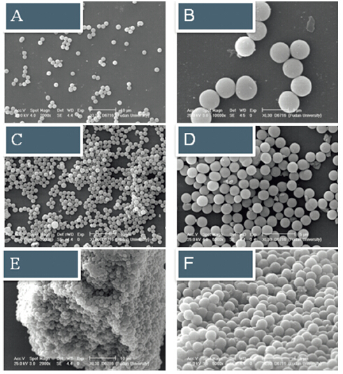
3. Results and discussion 3.1. The interior carbonization of S1The MSSs were carbonized with different concentrations of sugar as shown in the SEM images shown in Fig. 2. It can be seen that the original sphere morphology of MSSs was reserved with its diameter at around 1.5 mm (Fig. 2A-D). At a high concentration of sugar at 60 wt%,the spheres were connected with each other and formed a bulky solid easily (Fig. 2E and F).

|
Download:
|
| Fig.2. SEM images of (A and B) C-MSS-1, (C and D) C-MSS-2 and (E and F) C-MSS-3 with concentrations of sugar at 20 wt%, 40 wt% and 60 wt%, respectively. | |
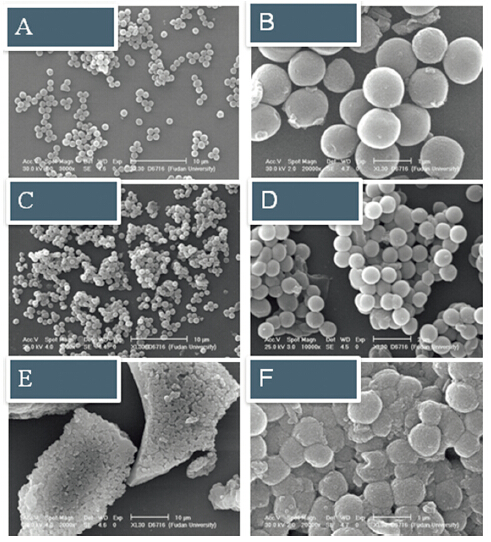
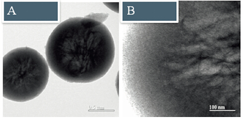
The C-MSSs were treated with an HF solution to remove the silica sphere and the corresponding samples of C-HSM-1,C-HSM-2 and C-HSM-3 were obtained. As shown in Fig. 3,the spheres were kept at 1.5 mm without the destruction of its framework after the HF treatment. The same trend with high concentrations of sugar could also be observed with bulky product obtained. The TEM images of C-HSM-2 at different magnifications showed that an interconnected carbon network was successfully formed inside the spheres (Fig. 4A and B). The EDS results indicated that the molar content of carbon was above 99% and the sphere was composed of carbon with the silica template totally dissolved,which further proved that the carbon network was generated as expected. In order to prepare the individual spheres instead of the bulky ones, the sugar concentration at 40 wt% was chosen for the following experiments.

|
Download:
|
| Fig.3. 3. SEM images of (A and B) C-HSM-1, (C and D) C-HSM-2 and (E and F) C-HSM-3 with concentrations of sugar at 20 wt%, 40 wt% and 60 wt%, respectively. | |

|
Download:
|
| Fig.4. TEM images of C-HSM-2 at (A) low and (B) high magnifications. | |
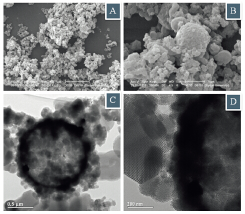
For the carbon modification of S1 with Pt encapsulated,the HF solution was replaced by the precursor of the hydrothermal treatment (Fig. 5A). The dissolved silica would serve as the silica source for the growing of the outside seeds of silicalite-1 and the Pt-C-HSM with both the encapsulated Pt and carbon being formed. The SEM picture (Fig. 5B) showed that the samples were with crude surface at the spheres and the nano-particles were tightly connected. The typical core-shell structure of S1 was presented in the TEM image (Fig. 5C) with the thickness of silicalite-1 shell at 150 nm and the diameter of carbon core at 1 mm. The ordered network in the interior carbon could be clearly seen from the highresolution TEM images (Fig. 5D) and the Pt nano-particles were uniformly dispersed with a small size of 4-6 nm. The EDS tests further confirmed that the S1 was successfully modified with a thin zeolite shell and a thick carbon core. The molar content of Pt in the modified S1 was 0.09%.

|
Download:
|
| Fig.5. (A) Schematic illustration, (B) SEM and (C and D) TEM images of Pt-C-HSM. | |
Fig. 6 presents the SEM and TEM images of S1@meso-1 obtained under acid conditions with P123 as the template. The microcapsular structure was crashed with a strong acid (HCl) and the disordered nanoparticles as well as a tiny amount of the reserved microcapsules were observed in the SEM picture (Fig. 6A and B). The micro-particles with irregular morphologies were formed at the surface of the S1 (Fig. 6B). The TEM characterization displayed that the hollow zeolite microcapsule was surrounded by numerous nano-particles and the highly ordered mesopore was fabricated at its surface. However,such mesopore did not disperse well and there were still some gaps remained between the S1 and the mesopore (Fig. 6C and D).

|
Download:
|
| Fig.6. (A and B) SEM and (C and D) TEM images of S1@meso-1. | |
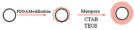
The S1 was first modified with polyelectrolyte PDDA to positively charge the outside shell [20],which would have a much better connection with the TEOS and the CTAB to obtain a closely connected mesoporous layer. As the applying of template P123 usually required acidic conditions that would destroy the zeolite framework and led to the collapse of the microcapsule easily,the template of CTAB that could function under neutral conditions became an excellent candidate for the mesoporous modification of S1 (Scheme 1).

|
Download:
|
| Scheme 1. The formation of uniform S1@meso using PDDA modification. | |
Fig. 7 displays the SEM and TEM images of S1@meso-2. As expected,the sphere structure of zeolite microcapsules could maintain well in the neutral system and the nano-particles were tightly dispersed around its surface (Fig. 7A-C). The TEM picture showed that there was a thin layer of disordered mesopore outside the hollow capsules (Fig. 7D-F). When the amount of TEOS was increased,sufficient silica source for the formation of S1@meso-3 was supplied and the edges of the distinct nanoparticles gradually disappeared with a thick silica layer being formed outside (Fig. 8A-C). The TEM characterization suggested that a uniform mesoporous structure was successfully generated. The typical wormlike mesopore layer with the thickness at 200 nm could be observed from the HRTEM (Fig. 8D-F). Besides, the most important point for S1@meso-3 is its real nano-scale combinationwithout gaps between the outsidemesopore and the shell of S1.

|
Download:
|
| Fig.7. (A)–(C) SEM and (D)–(F) TEM images of S1@meso-2 at different locations and magnifications. | |

|
Download:
|
| Fig.8. (A)–(C) SEM and (D)–(F) TEM images of S1@meso-3 at different locations and magnifications. | |
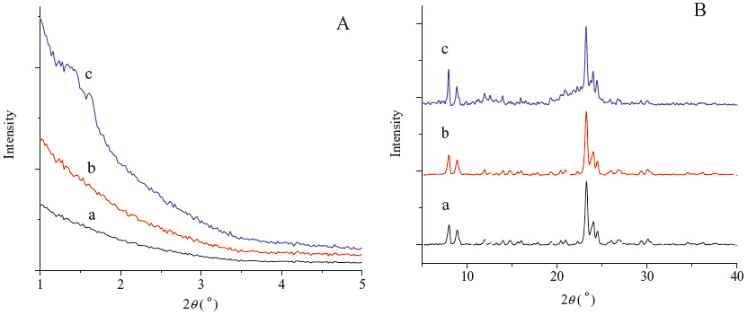
The mesoporous modification of S1 could be further proven by XRD tests at small and wide angles (Fig. 9). The S1 itself was tested as are reference. Since the zeolite microcapsule was composed of the well crystallized nano-particles,there was no signal appeared at 2θ = 1°-5° in the XRD patterns (Fig. 9A-a). After the modification of mesopores for S1@meso-2 with a very thin meso-layer,no big difference was observed at small angles of XRD (Fig. 9A-b). While for S1@meso-3 with a thick meso-layer,the peaks belonged to mesopores clearly appeared at 2θ = 1°-2° (Fig. 9A-c). The XRD patterns for S1@meso-2 at wide angles clearly showed that a different diffraction spectrum was observed compared with S1 and the typical peaks of the MFI structure at 2θ = 20°-25° were influenced by the thick disordered meso-layer with sufficient amount of TEOS and a broad peak was presented (Fig. 9B-c).

|
Download:
|
| Fig.9. (A) Small and (B) wide angles of XRD patterns for (a) S1, (b) S1@meso-2 and (c) S1@meso-3. | |
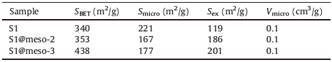
The nitrogen adsorption and desorption plot of different samples are shown in Fig. 10. The surface area and micropore volume were calculated by the BET and t-plot methods and listed in Table 1. As can be seen from the results,the hysteresis loop gradually became obvious with the successful modification of mesopores. The SBET was increased from 340 m2/g of S1 to 438 m2/g of S1@meso-3. At the same time,the value of Vmicro for the samples was kept at 0.1 cm3/g,which further confirmed the good crystallinity and the opened structure of the zeolitic shell.

|
Download:
|
| Fig.10. Representative N2 adsorption–desorption isotherms of (A) S1, (B) S1@meso-2 and (C) S1@meso-3. | |
| Table 1 Textural property of different samples. |
This paper mainly introduced a deep modification process of zeolite microcapsules. At the external shell,the S1 was successfully modified with a mesoporous layer. While inside the S1,a mesoporous carbon network could be successfully formed through the injection of proper concentrations of sugar into the mesoporous silica spheres (MSSs). Each modified S1 was extensively characterized. It was found that the uniformity of the microcapsule was dependent on the sugar concentrations. The nano-particles of the encapsulated Pt species inside the MSSs could be dispersed well at the carbon network within the capsule. On the other side, appropriate acidity of the system was crucial for the morphology control of S1 during the fabrication of the mesoporous layer outside the microcapsule. The PDDA modification on the S1 would be beneficial for the combination of the meso-layer and the shell of S1 at nano-scale level. Besides,the thickness of the mesoporous layer could be controlled by modulating the content of silica. These functionalized microcapsules could be potential candidates as multifunctional catalysts.
AcknowledgmentsThis work was also supported by National Key Basic Research Program of China (Nos. 2013CB934101 and 2009CB623500), Science and Technology Commission of Shanghai Municipality (No. 11JC1400400),National Plan for Science and Technology (No. 14-PET827-02) and Shanghai Postdoctoral Scientific Program (No. 13R21422000).
| [1] | A. Corma, From microporous to mesoporous molecular sieve materials and their use in catalysis, Chem. Rev. 97 (1997) 2373-2420. |
| [2] | M.E. Davis, Ordered porous materials for emerging applications, Nature 417 (2002) 813-821. |
| [3] | D. Trong On, S. Kaliaguine, Zeolite-coated mesostructured cellular silica foams, J. Am. Chem. Soc. 125 (2003) 618-619. |
| [4] | G.J. de, A.A. Soler-illia, C. Sanchez, B. Lebeau, J. Patarin, Chemical strategies to design textured materials: from microporous and mesoporous oxides to nano net works and hierarchical structures, Chem. Rev. 102 (2002) 4093-4138. |
| [5] | T.O. Do, A. Nossov, M.A. Springuel-Huet, et al., Zeolite nanoclusters coated onto the mesopore walls of SBA-15, J. Am. Chem. Soc. 126 (2004) 14324-14325. |
| [6] | C. Galeano, R. Guttel, M. Paul, et al., Yolk-shell gold nanoparticles as model materials for support-effect studies in heterogeneous catalysis: Au, @C and Au, @ZrO2for CO oxidation as an example, Chem. Eur. J. 17 (2011) 8434-8439. |
| [7] | W.R. Zhao, J.L. Gu, L.X. Zhang, H.R. Chen, J.L. Shi, Fabrication of uniform magnetic nanocomposite spheres with a magnetic core/mesoporous silica shell structure, J. Am. Chem. Soc. 127 (2005) 8916-8917. |
| [8] | J. Kim, J.E. Lee, J. Lee, et al., Magnetic fluorescent delivery vehicle using uniform mesoporous silica spheres embedded with monodisperse magnetic and semiconductor nanocrystals, J. Am. Chem. Soc. 128 (2006) 688-689. |
| [9] | S.H. Joo, J.Y. Park, C.K. Tsung, et al., Thermally stable Pt/mesoporous silica core- shell nanocatalysts for high-temperature reactions, Nat. Mater. 8 (2009) 126-131. |
| [10] | Y.H. Deng, Y. Cai, Z.K. Sun, et al., Multifunctional mesoporous composite microspheres with well-designed nanostructure: a highly integrated catalyst system, J. Am. Chem. Soc. 132 (2010) 8466-8473. |
| [11] | F. Schuth, W. Schmidt, Microporous and mesoporous materials, Adv. Mater. 14 (2002) 629-638. |
| [12] | Y. Wan, D.Y. Zhao, Controllable soft-templating approach to mesoporous silicates, Chem. Rev. 107 (2007) 2821-2860. |
| [13] | A. Vinu, V. Murugesan, W. Bohlmann, M. Hartmann, An optimized procedure for the synthesis of AlSBA-15 with large pore diameter and high aluminum content, J. Phys. Chem. B 108 (2004) 11496-11505. |
| [14] | A. Vinu, J. Justus, C. Anand, et al., Hexagonally ordered mesoporous highly acidic AlSBA-15 with different morphology: an efficient catalyst for acetylation of aromatics, Microporous Mesoporous Mater. 116 (2008) 108-115. |
| [15] | Y.H. Deng, D.W. Qi, C.H. Deng, X.M. Zhang, D.Y. Zhao, Superparamagnetic highmagnetization microspheres with an Fe3O4@SiO2 core and perpendicularly aligned mesoporous SiO2 shell for removal of microcystins, J. Am. Chem. Soc. 130 (2008) 28-29. |
| [16] | Z.M. Wang, W.D. Wang, N. Coombs, N. Soheilnia, G.A. Ozin, Graphene oxideperiodic mesoporous silica sandwich nano composites with vertically oriented channels, ACS Nano 4 (2010) 7437-7450. |
| [17] | X.F. Qian, B. Li, Y.Y. Hu, et al., Exploring meso-/microporous composite molecular sieves with core-shell structures, Chem. Eur. J. 18 (2012) 931-939. |
| [18] | J.S. Yu, S.B. Yoon, Y.J. Lee, K.B. Yoon, Fabrication of bimodal porous silicate with silicalite-1 core mesoporous shell structures and synthesis of nonspherical carbon and silica nano cases with hollow core/mesoporous shell structures, J. Phys. Chem. B 109 (2005) 7040-7045. |
| [19] | Y. Han, P. Pitukmanorom, L. Zhao, J.Y. Ying, Generalized synthesis of mesoporous shells on zeolite crystals, Small 7 (2011) 326-332. |
| [20] | L. Xu, Y.J. Ren, H.H. Wu, et al., Core/shell-structured TS-1@mesoporous silicasupported Au nanoparticles for selective epoxidation of propylene with H2 and O2, J. Mater. Chem. 21 (2011) 10852-10858. |
| [21] | X.F. Qian, J.M. Du, B. Li, et al., Controllable fabrication of uniform core-shell structured zeolite@SBA-15 composites, Chem. Sci. 2 (2011) 2006-2016. |
| [22] | Y. Seo, K. Kim, Y. Jung, R. Ryoo, Synthesis of mesoporous carbons using silica templates impregnated with mineral acids, Microporous Mesoporous Mater. 207 (2015) 156-162. |
| [23] | B. Sakintuna, Y. Yü rüm, Templated porous carbons: a review article, Ind. Eng. Chem. Res. 44 (2005) 2893-2902. |
| [24] | Y.R. Liu, J. Zhang, Influence of pore symmetries on the super capacitive performance of mesoporous carbons co-templated by F127 and PDMS-PEO, Microporous Mesoporous Mater. 206 (2015) 81-85. |
| [25] | X. Feng, G.E. Fryxell, L.Q. Wang, et al., Functionalized mono layers on ordered mesoporous supports, Science 276 (1997) 923-926. |
| [26] | S.H. Joo, S.J. Choi, I. Oh, et al., Ordered nanoporous arrays of carbon supporting high dispersions of platinum nanoparticles, Nature 412 (2001) 169-172. |
| [27] | X.C. Xu, C.S. Song, J.M. André sen, B.G. Miller, A.W. Scaroni, Preparation and characterization of novel CO2 "molecular basket" adsorbents based on polymer- modified mesoporous molecular sieve MCM-41, Microporous Mesoporous Mater. 62 (2003) 29-45. |
| [28] | H.S. Zhou, S.M. Zhu, I. Honma, K. Seki, Methane gas storage in self-ordered mesoporous carbon (CMK-3), Chem. Phys. Lett. 396 (2004) 252-255. |
| [29] | S.R. Chen, Y.P. Zhai, G.L. Xu, et al., Ordered mesoporous carbon/sulfur nanocomposite of high performances as cathode for lithium-sulfur battery, Electrochim. Acta 56 (2011) 9549-9555. |
| [30] | M.H. Zhang, A.X. Sun, Y.L. Meng, et al., High activity ordered mesoporous carbonbased solid acid catalyst for the esterification of free fatty acids, Microporous Mesoporous Mater. 204 (2015) 210-217. |
| [31] | J. Shi, N. Ren, Y.H. Zhang, Y. Tang, Studies on formation of hollow silicalite-1 microcapsules, Microporous Mesoporous Mater. 132 (2010) 181-187. |
| [32] | J. Shi, X. Li, Q.R. Wang, Y.H. Zhang, Y. Tang, Platinum-encapsulated zeolitically microcapsular catalyst for one-pot dynamic kinetic resolution of phenylethylamine, J. Catal. 291 (2012) 87-94. |
| [33] | J. Shi, L.F. Chen, N. Ren, Y.H. Zhang, Y. Tang, Zeolitic microcapsule with encapsulated platinum nanoparticles for one-pot tandem reaction of alcohol to hydrazone, Chem. Commun. 48 (2012) 8583-8585. |