 2015, Vol.26


The best afterglow phosphor known till now is SrAl2O4:Eu2+, Dy3+ which is a commercial phosphor and may have afterglow for more than 20 h. Unfortunately, exposition to water may impair the luminescence properties of these materials which limits their use e.g. in the paints as a pigment. a new kind of long lasting phosphors, Eu2+, Dy3+ co-doped silicates M2MgSi2O7 (M = Ca, Sr) with afterglow time longer than 20 h has been developed that shown better afterglow in even liquids [1]. Eu2+ ion acts as the luminescent center, and it is known that some rare earth (R3+) co-dopants enhance the persistent luminescence obtained with Eu2+ doping alone. The exact role of the co-dopants and that of other lattice defects is uncertain, but the R3+ ions have been suggested to trap holes or electrons or just to create/modify defects due to charge compensation [2, 3]. The Eu2+-doped dibarium magnesium disilicates with luminescence spectrum (λmax = 505 nm) are ideal for the human eye making the materials very suitable to practical applications [4, 5]. In this paper, Ba2MgSi2O7:Eu2+, Dy3+ phosphors with the different concentrations of co-dopant were prepared using high temperature the solid state reaction. The photoluminescence (PL) studies were done to identify the phosphor with optimum PL intensity. The PL decay of prepared samples was also carried out to recognize the concentration of co-dopant for superior afterglow properties.
2. ExperimentalThe phosphor of Ba2MgSi2O7:Eu2+, Dy3+ powder of different concentrations (0.1, 0.2, 0.5, 1.0, 1.5, 2.0 mol%) of Dy3+ were prepared by solid state reaction keeping Eu2+ concentration constant. The starting materials SiO2, BaCO3, MgO, Dy2O3 and Eu2O3 were thoroughly ground for approximately 1 h in a mortar, pre-sintered at 900 ℃, then fired at 1300 ℃ for approximately 2 h, with H3BO3 (1.6 mol%) used as flux. The phosphor was irradiated with a 365-nm UV source then heated at 6.7 ℃/s for thermoluminescence (TL) measurements. Thermally stimulated luminescence glow curves were recorded at room temperature by use of a Nucleonix (Hyderabad, India) I1009 TLD reader. SEM instrument used was SU 6600-FESEM from Hitachi having standard tungsten filament.
3. Results and discussionFig. 1 shows the comparison between observed, calculated and standard (matched) XRD pattern of Ba2MgSi2O7:Eu, Dy. Matching of the pattern is done using match! version 2.3.1. Experimental XRD pattern was matched convincingly with crystallographic open database (COD) card No. 96-810-0590 with Figure of Merit (FoM) of 0.8600. This is already reported XRD pattern of Ba2ZnSi2O7. It indicates that phases formed are very similar in case of Ba2ZnSi2O7 and Ba2MgSi2O7:Eu2+, Dy3+.

|
Download:
|
| Fig. 1.Comparison of observed, calculated and standard (batched) XRD pattern of Ba2MgSi2O7:Eu, Dy. | |
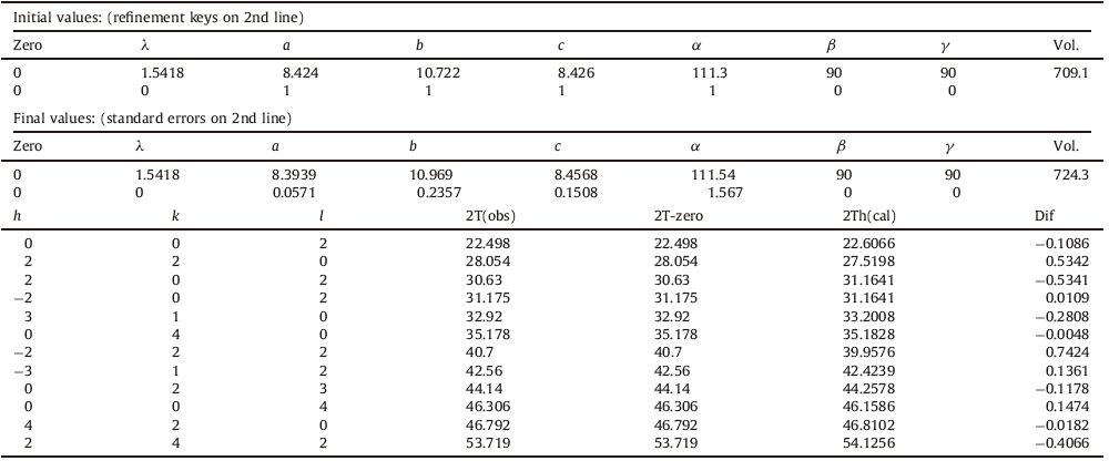
The datasheet provided by match version 2.3.1 expressed that prepared sample is monoclinic with C12/c1 (15) space group. Table 1 presents refined lattice parameters of the phosphor Ba2MgSi2O7 with Eu, Dy (0.5:1.5 mol%). The values of lattice parameters of the phosphor available in COD card No. 96-810- 0590. Refinement is done using Celref version 3 (Collaborative Computational Project No. 14 [CCP14] for Single Crystal and Powder Diffraction Birkbeck University of London and Daresbury Laboratory, London, UK). The calculated spectra confirmed the presence of monoclinic Ba2MgSi2O7. The calculated lattice parameters are shown in Table 1 and are slightly greater than values obtained in case of standard COD card. This may be due to the presence of Eu2+ (dopant) and Dy3+ (co-dopant) ions having greater ionic radii than Ba2+ ions. There are a few extra peaks in observed XRD pattern, which could be due a great number of stacking faults induced by the presence of the doping ions and also due to secondary phases and impurities formed during the elaboration process [4].
|
|
Table 1 Refined lattice parameters. |
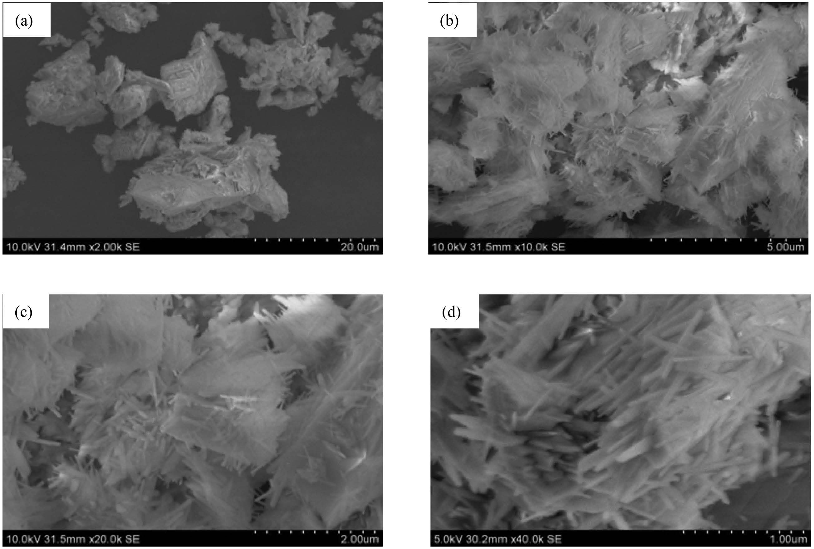
The grain size and morphological investigations of prepared phosphor in the process were carried out with a scanning electron microscope (SEM). The morphologies were taken at 2000×, 10, 000×, 20, 000×, and 40, 000× magnification.
As we know that scanning electron microscope (SEM) can investigate microstructures of samples, such as surface morphology, composition, and other properties. The surface morphology of prepare sample, phosphor is shown in Fig. 2. From the SEM images, it is clear that the particles have some agglomerations. But these agglomerated particles have uniform surfaces and similar particle size distribution. It seems that secondary particles are also attached to each other this is why the average particle size is about few micrometers and the morphology can be described as grass-like.

|
Download:
|
| Fig. 2.SEM images of Ba2MgSi2O7:Eu, Dy. (a) 2000×, (b) 10,000×, (c) 20,000× and (d) 40,000×. | |
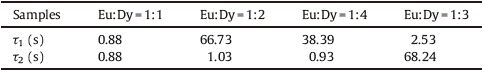
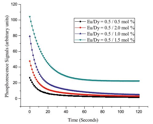
The comparison of decay curves of all the samples are shown in Fig. 3. All the samples were excited under Ultraviolet radiations for 2 min at room temperature. It is clear that all the phosphors show a rapid decay with subsequent persistence luminescence. Intensity of emission at wavelength 505 nm [4] and decay rate of the phosphors are different for different Eu/Dy ratios. The emission intensity and afterglow increases with increasing content of Dy, and it is maximum for Eu/Dy ratio of 1:3 after which emission intensity and afterglow time decreases which may be ascribed to concentration quenching of Dy3+ ions.

|
Download:
|
| Fig. 3.Phosphorescence decay curve of Ba2MgSi2O7:Eu2+, Dy3+ for different samples. | |
Since the decay curve includes rapid and slow decaying process, the decay curves are evaluated by fitting into double exponential equation which expresses the pattern of decay. The equation of fitting is as follows:

The result expressed in Table 2 indicates that afterglow property of the samples is increasing with increasing content of Dy3+. When the co-dopant (Dy3+) is 1.5 mol% its intensity as well as afterglow is maximum but when concentration goes beyond this (2 mol%) intensity and afterglow decreases suddenly.
|
|
Table 2 PL decay constant for different samples. |
From the decay curves as shown in Fig. 3, it is clear that the decay rate of the afterglow of phosphors changed with the amount of Dy3+ concentration. The co-doped Dy3+ acts as trap centers [8, 9] that trap the electrons generated during the exposure of phosphor to excitation source. To investigate the variation of phosphorescence intensity according to Dy concentration, we kept the doped amount of Eu at 0.5 mol% and changed the co-doped concentration of Dy. On increasing Dy concentrations, the phosphorescence signals increased as shown in Fig. 3. When the co-doped amount of Dy was 1.5 mol%, the phosphor showed the longest persistency. But as the concentration of Dy was above 1.5 mol%, the intensity of luminescence signals and persistency decreased sharply. It may be predicted that small amount of Dy is not sufficient to form enough trap defects in the Ba2MgSi2O7 matrix to trap sufficient electrons. However, if the amount of doped Dy is greater than 1.5 mol%, it may cause the concentration quenching and reduce the emission intensity. The mechanism of phosphorescence in silicate phosphor has been explained by many researchers[6, 9, 10, 11, 12] and may be elaborated as: on receiving exposure to excitation source, an electron of Eu2+ (4f7) is promoted to the 4f65d1 band followed by either direct or phonon assisted escape of the electron from Eu2+ to the host conduction band. The lattice defects close to the bottom of the host conduction band traps the electrons. Huge numbers of electrons are trapped by the traps assisted by Dy3+ at various depths [8] making an important role of Dy3+ during the long afterglow. After the removal of excitation source, the captured electrons near the host conduction band released to the conduction band with thermal energy and consequent recombination of them with the emitting Eu2+/Eu3+ centers lead the persistent afterglow. Thus, the major cause for the persistent afterglow is the number of electrons captured in the traps and its depths from the bottom of the conduction band of host material [7].
In support of statement that, suitable trap are responsible for long lasting properties, thermoluminescence (TL) of the said phosphor with optimum long lasting properties (Eu/Dy = 0.5/1.5 mol%) has been done.
We used the following relationship between the frequency factor ‘s’ and the depth of the trap ‘E’ to calculated trap depths:

The sample was given 20 min of UV exposure and then TL glow curves were recorded for different delay times; starting immediately till 75 min. It was found that, the trap depths were in the range of 0.62-0.84 eV [4]. This range is one of the characteristics of good long lasting material and it is an indication of formation of appropriate traps responsible for elongating the time of afterglow. The value of trap depth increased with increasing delay time till 25 min then it changes randomly; this may be the reason why; the thermoluminescence decay rate is higher initially as compared to later. It may be concluded that the traps formed were getting deeper with increasing delay time which is responsible for decrease in decay rates [12, 13].
4. Conclusion (1) The emission is due to transitions of Eu2+ arising from sublevels of 4f65d1 configuration to 8S7/2 level of the 4f7 configuration.(2) Best afterglow was found when Eu/Dy ratio is 1/3.
(3) The afterglow intensity of the persistent phosphor depends on the densities of the traps electrons, while the duration of afterglow depends on the depth of the trapped electrons. The number of trapped charge carrier, in turn, depends on the concentration of oxygen vacancies/Dy3+ and the trap depth of it. For a suitable trap depth, the trap concentration is directly depends on the Dy ions or the concentration. Hence, optimum Dy concentration produces the longer afterglow duration with higher intensity.
(4) In support to the statement that formations of suitable traps are responsible for long afterglow, trap depth was calculated. The value of trap depth ranges between of 0.62-0.84 eV that indicated that traps are neither too shallower nor too deep. There are possibilities of re-trapping before the recombination. This elongates the afterglow.
| [1] | C.S. Shi, Y.B. Fu, B. Liu, et al., The roles of Eu2+ and Dy3+ in the blue long-lasting phosphor Sr2MgSi2O7:Eu2+, Dy3+, J. Lumin. 122-123(2007) 11-13. |
| [2] | S. Carlson, J. Hölsä, T. Laamanen, et al., X-ray absorption study of rare earth ions in Sr2MgSi2O7:Eu2+, R3+ persistent luminescence materials, Opt. Mater. 31(2009) 1877-1879. |
| [3] | H.Y. Wu, Y.H. Hu, X.J. Wang, Investigation of the trap state of Sr2MgSi2O7:Eu2+, Dy3+ phosphor and decay process, Radiat. Meas. 46(2011) 591-594. |
| [4] | R. Shrivastava, J. Kaur, V. Dubey, B. Jaykumar, S. Loreti, Photoluminescence and thermoluminescence investigation of europium- and dysprosium-doped dibarium magnesium silicate phosphor, Spectrosc. Lett. 48(2014) 179-183. |
| [5] | T. Aitasalo, D. Hreniak, J. Holsa, et al., Persistent luminescence of Ba2MgSi2O7:Eu2+, J. Lumin. 122-123(2007) 110-112. |
| [6] | T. Aitasalo, J. Hölsä, H. Jungner, M. Lastusaari, J. Niittykoski, Thermoluminescence study of persistentluminescence materials:Eu2+- and R3+-doped calcium aluminates, CaAl2O4:Eu2+, R3+, J. Phys. Chem. B 110(2006) 4589-4598. |
| [7] | P. Dorenbos, Mechanism of persistent luminescence in Eu2+and Dy3+codoped aluminate and silicate compounds, J. Electrochem. Soc. 152(2005) H107-H110. |
| [8] | H.N. Luitel, T. Watari, R. Chand, T. Torikai, M. Yada, Giant improvement on the afterglow of Sr4Al14O25:Eu2+, Dy3+ phosphor by systematic investigation on various parameters, J. Mater. 2013(2013) 613090. |
| [9] | T. Matsuzawa, Y. Aoki, N. Takeuchi, Y. Murayama, A new long phosphorescent phosphor with high brightness, SrAl2O4:Eu2+, Dy3+, J. Electrochem. Soc. 143(1996) 2670-2673. |
| [10] | F. Clabau, X. Rocquefelte, S. Jobic, et al., On the phosphorescence mechanism in SrAl2O4:Eu2+ and its codoped derivatives, Solid State Sci. 9(2007) 608-612. |
| [11] | P. Dorenbos, Mechanism of persistent luminescence in Sr2MgSi2O7:Eu2+; Dy3+, Phys. Status Solidi (B) 242(2005) R7-R9. |
| [12] | P. Dorenbos, Systematic behaviour in trivalent lanthanide charge transfer energies, J. Phys.:Condens. Matter 15(2003) 8417-8434. |
| [13] | R. Chen, Thermally stimulated current curves with non-constant recombination lifetime, J. Phys. D:Appl. Phys. 2(1969) 371-375. |