|
收稿日期: 2019-01-06
基金项目: 中国科学院B类先导科技专项培育项目(编号:XDPB11);国家自然科学基金(编号:41671458,41771488)
第一作者简介: 邸凯昌,1967年生,男,研究员。研究方向为行星遥感制图与导航定位。E-mail:
dikc@radi.ac.cn
通信作者简介: 刘召芹,1973年生,男,博士,副研究员,研究方向为行星遥感制图与导航定位。E-main:
liuzq@radi.ac.cn
|
摘要
嫦娥四号着陆点的精确定位对于工程任务安全高效实施至关重要。本文基于嫦娥二号正射影像、LROC NAC正射影像、嫦娥四号降落相机影像、嫦娥四号监视相机影像等多源数据,利用影像特征匹配定位和单像视觉测量定位技术,确定了嫦娥四号着陆点的精确位置为(177.588°E,45.457°S)。本研究结果对综合利用多源数据深入开展着陆区科学研究具有重要意义。
关键词
嫦娥四号, 着陆点定位, 降落相机影像, 监视相机影像, 多源数据
Abstract
High precision localization of Chang’e-4 lander is critical to support safe and efficient mission operations. This paper presents the lander localization techniques, including image feature matching and monoscopic image measurement, using digital orthophoto maps of Chang’e-2 and LROC NAC images, descent camera images and monitoring camera image of Chang’e-4 lander. The lander location is precisely determined to be (177.588°E, 45.457°S) using these techniques. Localization of the lander in multiple datasets is valuable for synergistic scientific investigation of the landing site.
Key words
Chang’e-4, lander localization, descent camera image, monitoring camera image, multi-source data
Chang’e-4 (CE-4) is one of the key missions in the Chinese Lunar Exploration Program (Jia et al., 2018). With the support of the Queqiao (Magpie Bridge) relay satellite, CE-4 lunar probe has successfully landed on the far side of the moon in Von Kármán crater inside the South Pole-Aitken (SPA) basin at 10:26 am on January 3, 2019. The rover was successfully released from the lander and touched on the lunar surface on the same day. The success of this task marked the first soft landing of human spacecraft on the far side of the moon, which opened a new era of lunar exploration.
CE-4 lander localization is a fundamental work to support mission operations and science applications. High precision lander localization is of great significance for mission planning and safe and efficient implementation of the plans (Jia et al., 2014; Wan et al., 2014; Liu et al., 2015). In addition, determination of lander location in multiple datasets is particularly important for synergistic use of these datasets in scientific investigation of the landing site.
In the CE-4 mission operations, the Planetary Remote Sensing team of State Key Laboratory of Remote Sensing Science has been participating in the teleoperation tasks in Beijing Aerospace Control Center. Based on digital orthophoto maps (DOMs) generated from multiple orbital images, descending images from the lander’s descent camera, and the ground image from the lander’s monitoring camera, we have determined the lander location with high precision, using techniques of image feature matching, monoscopic image measurement, etc. The lander localization result has been used to support mission operations. In this short article, we briefly present the lander localization techniques and the results.
1 DATA
The high-resolution DOMs generated from orbital images are used as the reference maps for CE-4 lander localization. At present, Chang’e-2 (CE-2) orbital image data is the highest-resolution stereo image data that covers the entire moon surface (Ye et al., 2013). The 7 m resolution DOM and 20 m resolution digital elevation model (DEM) products of the entire moon have been produced and released (Li et al., 2018). The Lunar Reconnaissance Orbiter Camera (LROC) Narrow Angle Camera (NAC) has acquired high resolution (up to 0.5 m) images of nearly the entire moon. Because the LROC NAC is not a stereo imaging camera, it only acquired stereo images by side swing in a very limited number of regions (Robinson et al., 2010). The SLDEM2015 (Barker et al., 2016), generated by integration of a DEM generated by the Japanese Selenological and Engineering Explorer (SELENE) terrain camera and product of Lunar Reconnaissance Orbiter Laser Altimeter (LOLA), was also utilized for terrain analysis and sky visibility analysis.
A downward-looking descent camera identical to that on Chang’e-3 is mounted in the bottom of CE-4. The field of view (FOV) is 45.4° with the image size of 1024×1024 pixels (Liu et al., 2015; Wan et al., 2014; Liu et al., 2014). The camera took a series of images during the descending process. However, because of the limitation of the communication bandwidth, the strategies of selective sampling and image compression with a ratio of 1∶64 were used when transferring the descent images for quick view.
Three monitoring cameras, which have the image size of 1024×1024 pixels and 60° FOV, are mounted on the lander of CE-4. Monitoring cameras A and B are on the top of the lander, and monitor camera C is on the front panel of the lander with pitch angle of 15° and height of 1.42 m. Monitoring camera C can surveille the front view of the lander, which provides important information for safe separation of the rover from the lander.
2 LANDER LOCALIZATION TECHNIQUES AND RESULTS
A rough location of the lander is first determined by matching a medium resolution (similar to that of the orbital DOM) descent camera image to the orbital DOM. Next, the lander location is transferred to other descent images by sequential image matching. Finally, the lander location is refined by combining the monoscopic measurements from the monitoring camera image (Wan et al., 2014; Liu et al., 2015).
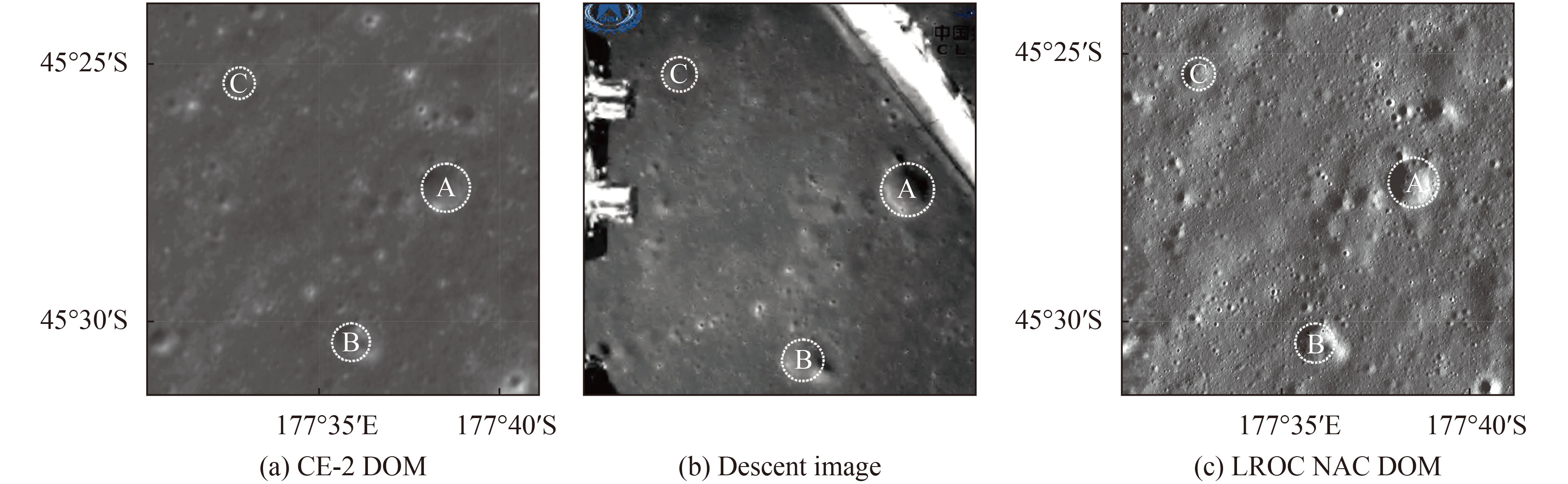
Because the descent images have been heavily compressed and even have some mosaic effects, these images have been pre-processed with the parabolic model to enhance the image quality and consequently to improve the image matching accuracy. For comparison purpose, the descent images are matched to both CE-2 and LROC NAC DOMs. Fig. 1 shows the image matching results, the middle image is a descent image taken at about 4 km altitude, the left and right images are the CE-2 and LROC NAC DOMs respectively. The labels A, B and C are the matched corresponding craters for lander localization.

During the mission, monoscopic measurement technique was applied to monitoring camera C (referred as the monitoring camera) in order to accomplish a series of tasks, including distance measurement from the lander, obstacle size measurement, and calculations of the illumination and communication occlusion envelopes. These measurements supported the decision making for rover-lander separation and high precision lander localization. More specifically, under the assumption that the front of the landing point is a horizontal plane, with monitoring camera image coordinates, its object space coordinates in the lander local coordinate system can be calculated according to the lander position and orientation and the camera installation matrix. Then the sizes of the rocks and impact craters as well as their distances to the lander can be calculated (Zhao et al., 2014). Based on the same method, the illumination and communication occlusion envelopes can be calculated according to the azimuth and elevation angles of the sun and the relay satellite, in order to avoid that the rover enters the lander-induced shadow or blind zone of communication when the rover is separated from the lander. Fig. 2 shows the monoscopic measurement results, in which the white lines indicate the distances to the front panel of the lander, and the diameter of the front crater is about 29 m.

Finally, the lander location was refined by combing the measurement results from the monitoring camera image and high resolution descent images. The lander location was precisely determined to be (177.588°E, 45.457°S) on the LROC NAC DOM. Meanwhile, the lander location was also determined on CE-2 DOM and SLDEM2015. Fig. 3 shows the CE-4 lander localization maps based on LROC NAC DOM, in which the right map is the zoom-in view of the rectangle in the left map.

3 CONCLUSION
This paper presented the techniques of CE-4 lander localization using orbital basemaps, descent images and monitoring camera image. The lander location was determined to be (177.588°E, 45.457°S) on the LROC NAC DOM. Meanwhile, the lander location was also determined on CE-2 DOM and SLDEM2015. High precision lander localization in multi-source data is valuable to support mission operations and synergistic scientific investigation of the landing site.
Acknowledgements: The authors gratefully acknowledge Beijing Aerospace Control Center for their support to this study. The authors also thank the institutions/organizations for making the data used in this paper available. The original images of Fig. 1(b) and Fig. 2 were downloaded from the website of China’s Lunar and Deep Space Exploration (http://www.clep.org.cn), thank you all here.
嫦娥四号(CE-4)是中国月球探测工程的一项重要任务(贾瑛卓 等,2018)。在“鹊桥”中继星的支持下,嫦娥四号探测器已于2019-01-03 10:26在月球背面预选着陆区南极-艾特肯盆地(South Pole-Aitken basin)内的冯·卡门撞击坑成功软着陆,并于当日成功实现两器分离,这是人类探测器首次在月球背面软着陆,开启了人类月球探测新篇章。
CE-4着陆点定位是支持工程任务实施和科学应用研究的基础性工作。着陆点的高精度定位对于后续巡视探测工程任务的规划和安全高效实施至关重要(贾阳 等,2014;万文辉 等,2014;Liu 等,2015)。目前,国内外多个探测任务已经获取了着陆区的多种遥感数据,在这些多源月球遥感数据中同时确定着陆点位置,不仅可实现着陆点的高精度定位,而且有利于综合利用多源数据对着陆区开展深入的科学研究。
在CE-4工程任务中,遥感科学国家重点实验室行星遥感团队在北京航天飞行控制中心参加了遥操作任务,基于多源轨道器影像底图、CE-4着陆器降落相机序列影像、着陆器监视影像等,利用影像特征匹配定位、单像视觉测量定位等技术,确定了着陆点的精确位置,支持了工程任务。本文简要介绍着陆点定位技术和CE-4着陆点定位结果。
1 数 据
月球表面大范围、高分辨率的轨道器影像产品是着陆器定位的基准底图,目前覆盖全月的最高分辨率立体影像数据为嫦娥二号(CE-2)轨道器影像(叶培建 等,2013),现已制成并发布了全月的7 m分辨率正射影像(DOM)及20 m分辨率的数字高程模型(DEM)产品(李春来 等,2018)。月球勘测轨道器相机LROC(Lunar Reconnaissance Orbiter Camera)的窄角相机NAC(Narrow Angle Camera)获取了几乎全月表高分辨率影像,其最高分辨率可达0.5 m,LROC NAC不是立体成像相机,所以只在少数区域通过相机侧摆获取立体像对(Robinson 等,2010)。本文以CE-2 制作的DOM和LROC NAC 影像制作的高分辨率DOM作为基准底图,同时还利用了由“月亮女神”(SELENE)搭载的地形测绘相机与月球激光高度计(LOLA)融合生成的SLDEM2015(Barker 等, 2016)进行了地形分析、天际线计算等。
CE-4着陆器底部以向下垂直视角安置了同嫦娥三号相同的降落相机。降落相机像幅为1024像素×1024像素,视场角为45.4°(Liu 等,2015;万文辉 等,2014;刘斌 等,2014),在着陆过程中获取了分辨率由低到高的序列降落影像。由于“鹊桥”中继星数据链路带宽有限,因而降落时以抽帧方式下传多张1∶64压缩的降落影像,这些数据用于与轨道器基准底图的匹配定位。
CE-4着陆器上安置了3台监视相机,像幅为1024像素×1024像素,视场角为60°。其中,监视相机A、B安装于着陆器顶部,监视相机C 以15°俯仰角安装于着陆器前面板1.42 m高处,用于监视着陆器正前方视场,为两器分离决策提供支持(赵强 等,2014)。
2 定位方法与结果
着陆点的定位首先通过中分辨率降落相机影像(与轨道器影像分辨率相当)与轨道器DOM的特征匹配,获得初始定位结果,进一步通过序列降落影像的匹配,实现着陆点位置的传递。最后通过监视相机影像的量测结果,精化着陆点的定位结果(万文辉 等,2014;Liu 等,2015)。
由于着陆过程中实时下传的高压缩比降落图像马赛克效应严重,因而匹配定位处理之前引入抛物线模型进行影像预处理,提升降落影像质量,进而提升降落影像与轨道器DOM的匹配精度。为了对比验证,将降落相机影像同时匹配到CE-2和LROC NAC影像底图。图1是匹配定位结果,其中图1(b)是4 km高度拍摄的降落影像,图1(a)和图1(c)分别是CE-2和LROC NAC DOM,标识A、B、C为识别出的用于定位的同名撞击坑。

工程中基于单像量测技术,利用监视相机C(下称监视相机)完成了着陆器前方距离和障碍物量测、光照及通信遮挡包络计算等任务,有效支持了两器分离决策及着陆点精确定位。监视相机单像量测技术是假设着陆点前方为一水平面,从监视相机像平面坐标,根据着陆器姿态及相机安装位置计算该点对应的着陆器月面局部坐标系下的物方坐标,进而确定两器分离任务区域内石块和撞击坑大小及与着陆器的相对距离(赵强 等,2014)。利用同样方法根据太阳及中继星的方位角和高度角计算光照和通信遮挡,避免在两器分离时巡视器停留在阴影或通信盲区。图2展示了监视相机单像量测结果,白色横线表示到着陆器前面板的距离,前方撞击坑直径约为29 m。

最后,基于监视相机影像量测结果,结合降落相机高分辨率影像对着陆点位置进行精化,得到着陆点在LROC NAC基准底图上的精确位置为(177.588°E, 45.457°S)。同时,在嫦娥二号DOM和SLDEM2015中也确定了着陆点的精确位置。图3为以LROC NAC底图为基准的嫦娥四号着陆点定位图,其中图3(b)是图3(a)方框中的局部放大图。

3 结 论
本文简要介绍了CE-4着陆点定位方法和结果,利用轨道器影像底图、着陆器降落相机影像、着陆器监视相机影像,通过影像匹配和视觉测量定位技术,确定了着陆点的位置,着陆点在LROC NAC基准底图上的精确位置为(177.588°E, 45.457°S)。同时,着陆点位置也精确地定位到CE-2 DOM及SLDEM2015中。CE-4着陆点的精确定位,支持了工程任务的实施,也有助于综合利用多源数据开展着陆区科学研究。
志 谢 衷心感谢北京航天飞行控制中心对本研究的支持,并感谢本研究中所用数据的生产和发布单位!文中图1(b)和图2原始图像来源于中国探月与深空探测网(http://www.clep.org.cn),在此一并感谢!
参考文献(References)
-
( Barker M K, Mazarico E, Neumann G A, Zuber M T, Haruyama J, Smith D E. 2016. A new lunar digital elevation model from the Lunar Orbiter Laser Altimeter and SELENE Terrain Camera. Icarus, 273 : 346–355. [DOI: 10.1016/j.icarus.2015.07.039] )
-
( Jia Y, Liu S, Li M, Li Q, Peng S, Wen B, Ma Y and Zhang S. 2014. Chang’E-3 system pinpoint landing localization based on descent image sequence. Chinese Science Bulletin, 59 (19): 1838–1843. [DOI: 10.1360/N972014-00020] )
-
( Jia Y, Zou Y, Xue C, Ping J, Yan J and Ning Y. 2018. Scientific objectives and payloads of Chang’E-4 mission. Chinese Journal of Space Science, 38 (1): 118–130. [DOI: 10.11728/cjss2018.01.118] )
-
( Li C, Liu J, Ren X, Yan W, Zuo W, Lingli M, Zhang H, Yan S, Wen W, Tan X, Xiaoxia Z, Wenrui W, Qiang F, Liang G, Guangliang Z, Baochang Z, Jianfeng Y and Ouyang Z. 2018. Lunar Global High-precision Terrain Reconstruction Based on Chang’e-2 Stereo Images. Geomatics and Information Science of Wuhan University, 43 (4): 485–495. [DOI: 10.13203/j.whugis20170400] )
-
( Liu Z, Di K, Peng M, Wan W, Liu B, Li L, Yu T, Wang B, Zhou J, Chen H. 2015. High precision landing site mapping and rover localization for Chang’e-3 mission. Science China-physics Mechanics & Astronomy, 58 (1): 1–11. )
-
( Robinson M S, Brylow S M, Tschimmel M, Humm D C, Lawrence S J, Thomas P C, Denevi B W, Bowmancisneros E, Zerr J, Ravine M A. 2010. Lunar Reconnaissance Orbiter Camera (LROC) Instrument Overview. Space Science Reviews, 150 : 81–124. [DOI: 10.1007/s11214-010-9634-2] )
-
( Wan W , Liu Z, Liu Y, Liu B, Di K, Zhou J, Wang B, Liu C and Wang J. 2014. Descent Image Matching Based Position Evaluation for Chang’e-3 Landing Point. Spacecraft Engineering, 23 (4): 5–12. )
-
( Ye P, Huang J, Zhang Y and Meng L. 2013. Technological achievements of Chang’E-2 probe and prospect of deep space exploration in China. Science China: Technical Science, 7 : 467–477. [DOI: 10.1360/092013-229] )
-
( Zhao Q, liu Z, Wan W, Li W, Sun Y, Di K, Zhou J, Xi L and Tie W. 2014. Decision support for seperation of Chang’e-3 rover and lander based on monoscopic measurement using monitoring camera image. Journal of Remote Sensing, 18 (5): 981–987. [DOI: 10.11834/jrs.20144070] )
-
Barker M K, Mazarico E, Neumann G A, Zuber M T, Haruyama J, Smith D E. 2016. A new lunar digital elevation model from the Lunar Orbiter Laser Altimeter and SELENE Terrain Camera. Icarus, 273 : 346–355. [DOI: 10.1016/j.icarus.2015.07.039]
-
Jia Y, Liu S, Li M, Li Q, Peng S, Wen B, Ma Y and Zhang S. 2014. Chang’E-3 system pinpoint landing localization based on descent image sequence. Chinese Science Bulletin, 59 (19): 1838–1843. [DOI: 10.1360/N972014-00020] ( 贾阳, 刘少创, 李明磊, 李群智, 彭松, 温博, 马友青, 张烁. 2014. 利用降落影像序列实现嫦娥三号系统着陆点高精度定位. 科学通报, 59 (19): 1838–1843. [DOI: 10.1360/N972014-00020] )
-
Jia Y, Zou Y, Xue C, Ping J, Yan J and Ning Y. 2018. Scientific objectives and payloads of Chang’E-4 mission. Chinese Journal of Space Science, 38 (1): 118–130. [DOI: 10.11728/cjss2018.01.118] ( 贾瑛卓, 邹永廖, 薛长斌, 平劲松, 严俊, 宁远明. 2018. 嫦娥四号任务科学目标和有效载荷配置. 空间科学学报, 38 (1): 118–130. [DOI: 10.11728/cjss2018.01.118] )
-
Li C, Liu J, Ren X, Yan W, Zuo W, Lingli M, Zhang H, Yan S, Wen W, Tan X, Xiaoxia Z, Wenrui W, Qiang F, Liang G, Guangliang Z, Baochang Z, Jianfeng Y and Ouyang Z. 2018. Lunar Global High-precision Terrain Reconstruction Based on Chang’e-2 Stereo Images. Geomatics and Information Science of Wuhan University, 43 (4): 485–495. [DOI: 10.13203/j.whugis20170400] ( 李春来, 刘建军, 任鑫, 严韦, 左维, 牟伶俐, 张洪波, 苏彦, 温卫斌, 谭旭, 张晓霞, 王文睿, 付强, 耿良, 张广良, 赵葆常, 杨建峰, 欧阳自远. 2018. 基于嫦娥二号立体影像的全月高精度地形重建. 武汉大学学报•信息科学版, 43 (4): 485–495. [DOI: 10.13203/j.whugis20170400] )
-
Liu Z, Di K, Peng M, Wan W, Liu B, Li L, Yu T, Wang B, Zhou J, Chen H. 2015. High precision landing site mapping and rover localization for Chang’e-3 mission. Science China-physics Mechanics & Astronomy, 58 (1): 1–11.
-
Robinson M S, Brylow S M, Tschimmel M, Humm D C, Lawrence S J, Thomas P C, Denevi B W, Bowmancisneros E, Zerr J, Ravine M A. 2010. Lunar Reconnaissance Orbiter Camera (LROC) Instrument Overview. Space Science Reviews, 150 : 81–124. [DOI: 10.1007/s11214-010-9634-2]
-
Wan W , Liu Z, Liu Y, Liu B, Di K, Zhou J, Wang B, Liu C and Wang J. 2014. Descent Image Matching Based Position Evaluation for Chang’e-3 Landing Point. Spacecraft Engineering, 23 (4): 5–12. [DOI: 10.3969/j.issn.1673-8748.2014.04.002] ( 万文辉, 刘召芹, 刘一良, 刘斌, 邸凯昌, 周建亮, 王保丰, 刘传凯, 王镓. 2014. 基于降落图像匹配的嫦娥三号着陆点位置评估. 航天器工程, 23 (4): 5–12. [DOI: 10.3969/j.issn.1673-8748.2014.04.002] )
-
Ye P, Huang J, Zhang Y and Meng L. 2013. Technological achievements of Chang’E-2 probe and prospect of deep space exploration in China. Science China: Technical Science, 7 : 467–477. [DOI: 10.1360/092013-229] ( 叶培建, 黄江川, 张廷新, 孟林智. 2013. 嫦娥二号卫星技术成就与中国深空探测展望. 中国科学: 技术科学, 7 : 467–477. [DOI: 10.1360/092013-229] )
-
Zhao Q, liu Z, Wan W, Li W, Sun Y, Di K, Zhou J, Xi L and Tie W. 2014. Decision support for seperation of Chang’e-3 rover and lander based on monoscopic measurement using monitoring camera image. Journal of Remote Sensing, 18 (5): 981–987. [DOI: 10.11834/jrs.20144070] ( 赵强, 刘召芹, 万文辉, 李巍, 孙义威, 邸凯昌, 周建亮, 席露华, 铁伟涛. 2014. 基于监视相机单像量测的嫦娥三号巡视器与着陆器分离决策支持. 遥感学报, 18 (5): 981–987. [DOI: 10.11834/jrs.20144070] )