Formation control of unmanned aerial vehicles (UAVs) can accomplish a task better than a single UAV and has been studied using various methods. UAVs are widely adopted in various situations[1-2]. However, the requirements nowadays have already overtaken the current abilities of a single UAV. In order to satisfy the requirements, different plans for the cooperation of many UAVs have been proposed by Chaumette[3] and Rasche[4], and the design of a method for multi-UAV formation is important[5]. Different methods have been proposed such as the leader-follower approach[6], artificial potential field[7], and sliding mode control[8].
Among these approaches, consensus is an effective and easy method for distributed control[9]. Using several simple consensus equations, UAVs can fly along complex trajectories. Consensus originates from the natural behavior of animals such as fish and birds. A single bird or fish is small and weak, but a population can hold a complicated formation. It is consensus that plays an essential role in this phenomenon. Vicsek[10] and Ren[9, 11-12] have achieved many results in this field. This paper adopts this method to design a controller for a multi-UAV formation.
There are two main parts of the consensus algorithm[13-14]. First, the formation is treated as a virtual rigid body, every UAV has a desired position and this acts as a point on the body. Using consensus, the UAVs' desired positions concentrate together and create the desired formation. However, a distance error always exists between the desired position and the real position for each UAV, and the second part of the algorithm deals with this problem by considering this error as a variable in consensus. By devising a useful algorithm, the error closes to zero as time tends to infinity. The real position for each UAV is the sum of the desired position and the error. In this way, UAVs with random initial locations always concentrate and fly along their predesigned routes. These two parts of the algorithm added to the communication networks of the individual vehicles comprise the whole UAV system[13-14]. However, consensus can only ensure that all the variables are close to the given state and does not know whether the values of variables at each moment are optimal. It is a good idea to improve consensus with optimal algorithms.
Pigeon-inspired optimization (PIO) is a novel swarm intelligence optimizer proposed by Duan and Qiao in 2014[15]. The method imitates pigeons' behavior when seeking a way back to their loft. It is believed that pigeons adopt different tools at different stages when returning home. In the beginning, compass and map factors are adopted[16], each pigeon's velocity is updated by the linear combination of its neighbors' (including itself) best locations and its former velocity. When pigeons approach home, some smart ones with good memories can recognize familiar landmarks which guide them[17], the others just need to follow these leaders. The second part of PIO is designed to concentrate the average location of all the pigeons. It is widely known that each optimizer fits one or several problems, and PIO was first proposed for air robot path planning[15, 18], image processing[17, 19], and orbit formations[20]. When it comes to the optimization of consensus mentioned above, disadvantages appear such as the trajectory closes to the desired trace with oscillation to an unsatisfactory degree[21]. This means that PIO needs to be modified and a pigeon-inspired optimization with slow diving strategy (SD-PIO) is proposed.
The remainder of this paper is organized as follows. In Section 2, details of the application of consensus in a multi-UAV formation are given. The construction of SD-PIO and the convergence analysis is considered in Section 3. In Section 4, the SD-PIO-based consensus algorithm is proposed for a multi-UAV formation, followed by numerical simulation and results analysis in Section 5. Finally, several conclusions concerning the use of optimal algorithms in consensus theory are drawn.
1 Controller design based on consensus 1.1 Multi-UAV formation controller designIt is supposed that each UAV possesses a moving coordinate system with three axes (x, y, and z). The shape of the UAV is ignored and a mass point model is used instead. This is because the time delay of an aircraft control loop is much shorter than that of the navigation and guidance loops. Therefore, when dealing with formation control, the UAV model can be simplified as a point, which means there is no need to consider each UAV's attitude. Under this assumption, all the UAV's x, y, and z axes are parallel.
Consensus means that multiple UAVs reach an agreement on a common state, e.g., the UAV's position. In detail, every UAV has its initial 3-dimensional position (x, y, z) in an inertial coordinate system, namely the ground coordinate system. The velocity of the original UAVi's moving coordinate system converges to the standard state of the virtual leader UAV10 by consensus. The UAV10's state consists of a time-varying position and predesigned velocity. In this way, all the UAVs' coordinates become one common moving coordinate system. After adding the relative position of each UAV in the moving coordinate system, the desired time-varying position is achieved for each UAV. When viewed as a mass of moving points, all these UAVs constitute a virtual body.
The formation method consists of both single-and double-integrator consensus algorithms. The latter aims to concentrate the UAVs with random initial positions and ensure that the desired positions of all the UAVs converge to points on the predesigned trajectory. The former ensures the distance error between the desired and the real position converges to 0 [14]. The real position of each UAV can be easily acquired and the UAV's trajectory is drawn.

|
Figure 1 Frame of consensus controller in multi-UAV formation |
For the formation problem in a multi-UAV system, the UAVs' states should include both position and velocity, and the control inputs are the accelerations [14]. This model is always described by second-order differentiation equations, and as a result, a consensus algorithm for double-integrator dynamics is required. The dynamic math model of the multi-UAV system is given below,
| $ \left\{ \begin{array}{l} {{\mathit{\boldsymbol{\dot \xi }}}_i} = {\mathit{\boldsymbol{\zeta }}_i}\\ {{\mathit{\boldsymbol{\dot \zeta }}}_i} = {\mu _i}\\ {\mathit{\boldsymbol{\xi }}_i} = {\left[ {{x_i}{y_i}{z_i}} \right]^{\rm{T}}} \end{array} \right. $ | (1) |
where ξi, ζi, μi∈R3 represent the position, the velocity and the acceleration of UAVi, respectively and xi, yi, zi are the 3-dimensional positions, i∈{1, 2, …, 10}. The consensus algorithm can be described as in Ref [14].
| $ \begin{array}{*{20}{c}} {{\mu _i} = \frac{1}{{{k_i}}}\sum\limits_{j = 1}^9 {{a_{ij}}\left[ {{{\dot \zeta }_j} - {\mathit{\boldsymbol{K}}_{ri}}\left( {{\xi _i} - {\xi _j}} \right) - {\mathit{\boldsymbol{K}}_{vi}}\left( {{\zeta _i} - {\zeta _j}} \right)} \right]} + }\\ {\frac{1}{{{k_i}}}{a_{i10}}\left[ {{{\dot \zeta }^r} - {\mathit{\boldsymbol{K}}_{ri}}\left( {{\xi _i} - {\xi ^r}} \right) - {\mathit{\boldsymbol{K}}_{vi}}\left( {{\zeta _i} - {\zeta ^r}} \right)} \right]} \end{array} $ | (2) |
Where aij is element (i, j)in the adjacency matrix
To attain the desired position for one single UAV in the moving coordinate system, the error between the desired and the real position should be treated as an extra variable, this can be described by single-integrator dynamics for simplicity. The math model can be described as
| $ {\rm{\dot e}}{{\rm{r}}_i} = {u_i} $ | (3) |
and the consensus algorithm is in Ref [9].
| $ {u_i} = - \sum\limits_{j = 1}^9 {{a_{ij}}\left( {{\rm{e}}{{\rm{r}}_i} - {\rm{e}}{{\rm{r}}_j}} \right)} $ | (4) |
| $ {{\tilde r}_i} = r{p_i} + {\rm{e}}{{\rm{r}}_i} $ | (5) |
Where

|
Figure 2 Formation structure for UAVs |
| $ \left\{ \begin{array}{l} \left( {\mathit{\boldsymbol{L}} \otimes {\mathit{\boldsymbol{I}}_3}} \right)\ddot \xi + \left( {b \otimes {\mathit{\boldsymbol{I}}_3}} \right){{\ddot \xi }^r} = - {\mathit{\boldsymbol{K}}_r}\left[ {\left( {\mathit{\boldsymbol{L}} \otimes {\mathit{\boldsymbol{I}}_3}} \right)\xi + \left( {b \otimes {\mathit{\boldsymbol{I}}_3}} \right){\xi ^r}} \right] - \\ {\mathit{\boldsymbol{K}}_v}\left[ {\left( {\mathit{\boldsymbol{L}} \otimes {\mathit{\boldsymbol{I}}_3}} \right)\xi + \left( {b \otimes {\mathit{\boldsymbol{I}}_3}} \right){\xi ^r}} \right]\\ \dot e = - \left( {\mathit{\boldsymbol{L}} \otimes {\mathit{\boldsymbol{I}}_3}} \right)e\\ r = \tilde r + \xi = {\rm{rp}} + {\rm{er}} + \xi \end{array} \right. $ | (6) |
where L9×9 is the Laplace matrix of the communication topology graph,
Equation (6) is the core of the multi-UAV controller, and r provides the necessary positional information for all the UAVs for use in the next step. After acquiring the target instructions, the UAVs fly toward their destinations.
1.2 Multi-UAV formation taskThe desired formation shape is designed as follows:
There are nine UAVs flying at two different heights, they are divided into three groups, each group containing three UAVs. In every small group, the UAVs form a triangle and these are the same size, so the UAVs fly symmetrically. The side length of the triangle and the distance between different triangles is much larger than the size of an UAV, so they can fly safely without danger of collision. The desired heights in Table 1 are relative values and the height of the origin of the moving coordinate system is their reference height, so when a UAV flies at zero or even a negative height, it is still acceptable. The blue star in Fig. 2 represents the center of the formation. x/m means distance along the x-axis in meters.
|
|
Table 1 Positions of 9 UAVs under the desired formation structure |
When designing the communication plan, the UAVs were numbered from 1 to 9. To clarify the plan, some background knowledge on topology and graph theory is required.
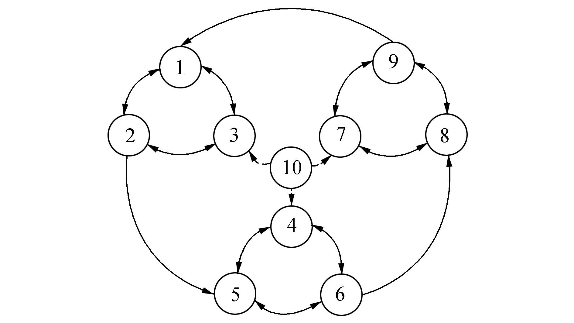
A graph with only vertices and arrows can be adopted to show the communication relationship among all the UAVs. Each UAV acts as a vertex, and an arrow from UAV1 to UAV2 means that UAV2 can receive information from UAV1. There is also a virtual leader named UAV10, which can emit an arrow to another UAV so that the latter knows the predesigned trajectory.
The communication topology among UAVs is described as a directed graph in Fig. 3. A graph with n vertices can be denoted by
|
Figure 3 Communication topology for multiple UAVs |
For consensus, the adjacency matrix and the Laplace matrix were acquired. The Laplace matrix
According to the sufficient and necessary condition of multi-UAV consensus, there is a directed spanning tree with its root UAV10, in the communication topology graph, and all the state variables converge to the state of the root as time tends to infinity[11].
2 Pigeon-inspired optimization with slow diving strategy 2.1 Basic pigeon-inspired optimization algorithmQiao [15] studied pigeon behavior when seeking their way home and proposed the two-stage algorithm. The first stage of PIO is the map and compass part.
| $ \begin{array}{*{20}{c}} {\left\{ \begin{array}{l} {v_i}\left( {t + 1} \right) = {v_i}\left( t \right) \cdot \exp \left( { - Rt} \right) + {\rm{rand}} \cdot \left( {{x_{{\rm{lbest}}}} - {x_i}} \right)\\ {x_i}\left( {t + 1} \right) = {x_i}\left( t \right) + {v_i}\left( {t + 1} \right) \end{array} \right.}\\ {{\rm{if}}\;t < {T_{{\rm{label}}}}} \end{array} $ | (7) |
In the formula above, the best local position
| $ {\rm{fitness}}\left( {{x_i}\left( t \right)} \right) = \left| {{x_i}\left( t \right) - {x_{i{\rm{standard}}}}\left( t \right)} \right| $ | (8) |
After calculating the distance between the desired and the present positions of all the pigeons, only half of the pigeons with lower fitness are selected for the iteration. This ensures that the positions of these pigeons converge to the desired position as fast as possible.
In the second part, the landmark operator is employed. Its update formula is:
| $ \begin{array}{*{20}{c}} {\left\{ \begin{array}{l} {N_p}\left( {t + 1} \right) = \frac{{{N_p}\left( t \right)}}{2}\\ {x_{iC}}\left( {t + 1} \right) = \frac{{\sum {{x_i}\left( t \right) \cdot f\left( {{x_i}\left( t \right)} \right)} }}{{\sum {f\left( {{x_i}\left( t \right)} \right)} }}\\ {x_i}\left( {t + 1} \right) = {x_i}\left( t \right) + {\rm{rand}} \cdot \left( {{x_{iC}}\left( {t + 1} \right) - {x_i}\left( t \right)} \right) \end{array} \right.}\\ {{\rm{if}}\;t \ge {T_{{\rm{label}}}}} \end{array} $ | (9) |
Apparently,
The problem in the former algorithm occurs mainly in the altitude part, the height of the UAV decreases too fast and it dives sharply. To slow the process, the update formula should be changed, not only to consider the best local position but also the slowest diving velocity. In the first part of PIO, the formula is not changed, but the method of acquiring the best local position is modified. The criterion is a linear combination of the distance error between the desired and the real positions and the diving speed. An UAV that dives very slowly is imitated by the others. This is the so-called "slow diving strategy". The update formula is:
| $ \begin{array}{*{20}{c}} {\left\{ \begin{array}{l} {v_i}\left( {t + 1} \right) = {v_i}t \cdot \exp \left( { - Rt} \right) + \\ \;\;\;\;\;\;\;\;\;\;\;\;\;\;\;r \cdot \left[ {\varphi \cdot \left( {{x_{{\rm{lbest}}}} - {x_i}} \right) + \left( {1 - \varphi } \right) \cdot {v_{{\rm{slow}}}}} \right]\\ {x_i}\left( {t + 1} \right) = {x_i}\left( t \right) + {v_i}\left( {t + 1} \right) \end{array} \right.}\\ {{\rm{if}}\;t < {T_{{\rm{label}}}}} \end{array} $ | (10) |
where
The second part of PIO should be modified in the following way: all the UAVs converge to the center of the flock, which is calculated by a combination of the UAV positions and the slowest diving speed. The update equation can be described as:
| $ \begin{array}{*{20}{c}} {\left\{ \begin{array}{l} {N_p}\left( {t + 1} \right) = \frac{{{N_p}\left( t \right)}}{2}\\ {x_{iC}}\left( {t + 1} \right) = \frac{{\sum {{x_i}\left( t \right) \cdot f\left( {{x_i}\left( t \right)} \right)} + 10 \cdot {x_{{\rm{slow}}}} \cdot f\left( {{x_{{\rm{slow}}}}} \right)}}{{\sum {f\left( {{x_i}\left( t \right)} \right) + 10 \cdot {x_{{\rm{slow}}}} \cdot f\left( {{x_{{\rm{slow}}}}} \right)} }}\\ {x_i}\left( {t + 1} \right) = {x_i}\left( t \right) + {\rm{rand}} \cdot \left( {{x_{iC}}\left( {t + 1} \right) - {x_i}\left( t \right)} \right) \end{array} \right.}\\ {{\rm{if}}\;t \ge {T_{{\rm{label}}}}} \end{array} $ | (11) |
where
Fitness function Eq. (10) remains. Each UAV has its own fitness value.
2.3 Convergence analysis of SD-PIO based on Banach fixed-point theoremIn this section, convergence analysis of SD-PIO is performed and a sufficient condition is proposed for the first part of SD-PIO (SD-PIO-I). The main method adopted to prove the stability of iteration is the Banach fixed-point theorem, as stated below:
A map T from a normed space
In the first part of SD-PIO, each pigeon updates its speed and location according to Eq. (10), which can be transformed as
| $ \begin{array}{*{20}{c}} {\left[ {\begin{array}{*{20}{c}} {{x_i}\left( {t + 1} \right)}\\ {{v_i}\left( {t + 1} \right)} \end{array}} \right] = \left[ {\begin{array}{*{20}{c}} {1 - r\varphi }&{\exp \left( { - Rt} \right)}\\ { - r\varphi }&{\exp \left( { - Rt} \right)} \end{array}} \right]\left[ {\begin{array}{*{20}{c}} {{x_i}\left( t \right)}\\ {{v_i}\left( t \right)} \end{array}} \right] + }\\ {r\left[ {\begin{array}{*{20}{c}} \varphi &{1 - \varphi }\\ \varphi &{1 - \varphi } \end{array}} \right]\left[ {\begin{array}{*{20}{c}} {{x_{{\rm{lbest}}}}}\\ {{v_{{\rm{slow}}}}} \end{array}} \right]} \end{array} $ | (12) |
when it considers all the pigeons,
where
| $ \begin{array}{*{20}{c}} {\mathit{\boldsymbol{F = }}\left[ {\begin{array}{*{20}{c}} {1 - r\varphi }&{}&{}&{\exp \left( { - Rt} \right)}&{}&{}\\ {}& \ddots &{}&{}& \ddots &{}\\ {}&{}&{1 - r\varphi }&{}&{}&{\exp \left( { - Rt} \right)}\\ {1 - r\varphi }&{}&{}&{\exp \left( { - Rt} \right)}&{}&{}\\ {}& \ddots &{}&{}& \ddots &{}\\ {}&{}&{ - r\varphi }&{}&{}&{\exp \left( { - Rt} \right)} \end{array}} \right]}\\ {\mathit{\boldsymbol{B}} = r\left[ {\begin{array}{*{20}{c}} \varphi &{}&{}&{1 - \varphi }&{}&{}\\ {}& \ddots &{}&{}& \ddots &{}\\ {}&{}&\varphi &{}&{}&{1 - \varphi }\\ \varphi &{}&{}&{1 - \varphi }&{}&{}\\ {}& \ddots &{}&{}& \ddots &{}\\ {}&{}&\varphi &{}&{}&{1 - \varphi } \end{array}} \right]}\\ {\mathit{\boldsymbol{u}}\left( {\mathit{\boldsymbol{z}}\left( t \right)} \right) = {{\left[ {{x_{{\rm{lbest1}}}}\left( t \right) \cdots {x_{{\rm{lbest}}n}}\left( t \right)\;\;{v_{{\rm{slow1}}}}\left( t \right) \cdots {x_{{\rm{slow}}n}}\left( t \right)} \right]}^{\rm{T}}}.} \end{array} $ |
If iteration
Denoting
Because the best local location and the slowest speed are among all the pigeons' locations and velocities,
| $ \begin{array}{*{20}{c}} {d\left( {T\left( {{z_1}} \right),T\left( {{z_2}} \right)} \right) = \mathop {\max }\limits_{1 \le i \le 2n} \left| {T\left( {{z_1}} \right),T\left( {{z_2}} \right)} \right| = }\\ {\mathop {\max }\limits_{1 \le i \le 2n} \left| {\mathit{\boldsymbol{F}}{z_1} + \mathit{\boldsymbol{B}}u\left( {{z_1}} \right) - \mathit{\boldsymbol{F}}{z_2} - \mathit{\boldsymbol{B}}u\left( {{z_2}} \right)} \right| = }\\ {{{\left\| {\mathit{\boldsymbol{F}}{z_1} + \mathit{\boldsymbol{B}}{K_1}{z_1} - \mathit{\boldsymbol{F}}{z_2} - \mathit{\boldsymbol{B}}{K_2}{z_2}} \right\|}_\infty }} \end{array} $ | (13) |
There is
| $ {L_j} = {F_{j \cdot }}\left( {{z_1} - {z_2}} \right) + {B_{j \cdot }}{\left[ {0 \cdots {x_{1a}} - {x_{2b}}\;0 \cdots {v_{1a}} - {v_{2b}}\;0 \cdots 0} \right]^{\rm{T}}} $ | (14) |
s.t.
| $ \begin{array}{*{20}{c}} {\left| {{L_j}} \right| = \left| {{F_{j \cdot }}\left( {{z_1} - {z_2}} \right) + {B_{j \cdot }}{{\left[ {0 \cdots {k_1}\Delta z\;0 \cdots {k_2}\Delta z\;0 \cdots 0} \right]}^{\rm{T}}}} \right| = }\\ {\left| {{F_{j \cdot }}\left( {{z_1} - {z_2}} \right) + {B_{j \cdot }}{{\left[ {0 \cdots {k_1} \cdots {k_2} \cdots 0} \right]}^{\rm{T}}}\Delta z} \right| \le }\\ {{{\left\| {\mathit{\boldsymbol{F}}\left( {{z_1} - {z_2}} \right) + \mathit{\boldsymbol{BK}}\left( {{z_1} - {z_2}} \right)} \right\|}_\infty } \le }\\ {{{\left\| {\mathit{\boldsymbol{F}} + \mathit{\boldsymbol{BK}}} \right\|}_\infty }{{\left\| {{z_1} - {z_2}} \right\|}_\infty } = {{\left\| {\mathit{\boldsymbol{F}} + \mathit{\boldsymbol{BK}}} \right\|}_\infty }d\left( {{z_1},{z_2}} \right)} \end{array} $ | (15) |
Where
The equation holds if and only if
The Banach fixed-point theorem requires
| $ \begin{array}{l} \Leftrightarrow \max \left\{ {\left| {1 - \varphi r + \exp \left( { - Rt} \right) + r{k_1}\varphi + r{k_2}\left( {1 - \varphi } \right)} \right|,} \right.\\ \;\;\;\;\;\left. {\left| { - \varphi r + \exp \left( { - Rt} \right) + r{k_1}\varphi + r{k_2}\left( {1 - \varphi } \right)} \right|} \right\} < 1\\ \Leftrightarrow \left\{ \begin{array}{l} - 1 < - \varphi r + \exp \left( { - Rt} \right) + r{k_1}\varphi + r{k_2}\left( {1 - \varphi } \right) < 0\\ 1 - \le {k_1},{k_2} \le 1,{k_1}{k_2} \ne 0 \end{array} \right. \end{array} $ | (16) |
Equation (16) is a sufficient condition for the convergence of SD-PIO-I, once it is satisfied, we have
| $ \left\{ \begin{array}{l} {x^ * } = {v^ * } + {x^ * }\\ {x^ * } = {x^ * } + \exp \left( { - Rt} \right){v^ * } + r\left[ {\varphi \left( {x_{{\rm{lbest}}}^ * - {x^c}} \right) + \left( {1 - \varphi } \right)v_{{\rm{slow}}}^ * } \right] \end{array} \right. $ | (17) |
Equation (17)
For the second part of SD-PIO, all the pigeons converge to the flock's center. Their trajectories can only contract and approach each other. In formation processes this part serves only as a transition, and as the traces do not diverge this second part satisfies the demands.
3 Multi-UAV formations with a SD-PIO-based consensus algorithmThe first three sections introduced consensus and SD-PIO, now this section uses them to optimize the trajectory of an UAV. When consensus is only applied to the planned routes of all the UAVs, there is unavoidable overshoot because of the distributed control plan itself. Every UAV has its own limited communication relationship, which means it cannot always receive the desired trajectory. For example,
UAV1 can never acquire the planned trajectory directly, it relies on UAV3 to pass on the information. If UAV3's initial altitude is much too high, it must dive to meet the desired trajectory. Because of inertia and a lack of forecasting, UAV3 can only produce positive additions to its height when it goes below the desired trajectory and this is the reason for overshoot. However, as for UAV1, only when its leader UAV3 flies below the proposed height does it begin to recognize that it should fly a bit higher, then its velocity is changed by Eq. (7), followed by its position. This process is much slower than a change in the desired route. As a result, the UAVs' trajectories dive sharply and appear to overshoot, then they converge to the desired trajectory. SD-PIO provides a gentle and slowly changing trajectory for each UAV at the start, then, as soon as the UAVs fly down and meet the desired trajectory, consensus starts to operate.
The formula of the combination of these two algorithms can be described as:
| $ \left\{ \begin{array}{l} x\left( {t + 1} \right) = x\left( t \right) + T \cdot \left( {v\left( {t + 1} \right) + {v_2}\left( {t + 1} \right)} \right)\\ v\left( {t + 1} \right) = v\left( t \right) + T \cdot a\left( {t + 1} \right)\\ a\left( {t + 1} \right) = - \left( {\left( {\mathit{\boldsymbol{L}} \otimes {\mathit{\boldsymbol{I}}_3}} \right) \cdot x\left( {t + 1} \right) + } \right.\\ \left. {\gamma \cdot \left( {\mathit{\boldsymbol{L}} \otimes {\mathit{\boldsymbol{I}}_3}} \right) \cdot v\left( {t + 1} \right)} \right) \cdot \\ \left( {\frac{1}{{\rm{ \mathsf{ π} }}} \times \arctan \left( {R \times \left( {t - {T_{{\rm{chg}}}}} \right)} \right) + 0.5} \right)\\ {v_2}\left( {t + 1} \right) = f\left( {x\left( t \right),v\left( t \right)} \right) \cdot \\ \left( { - \frac{1}{{\rm{ \mathsf{ π} }}} \times \arctan \left( {R \times \left( {t - {T_{{\rm{chg}}}}} \right)} \right) + 0.5} \right) \end{array} \right. $ | (18) |
where
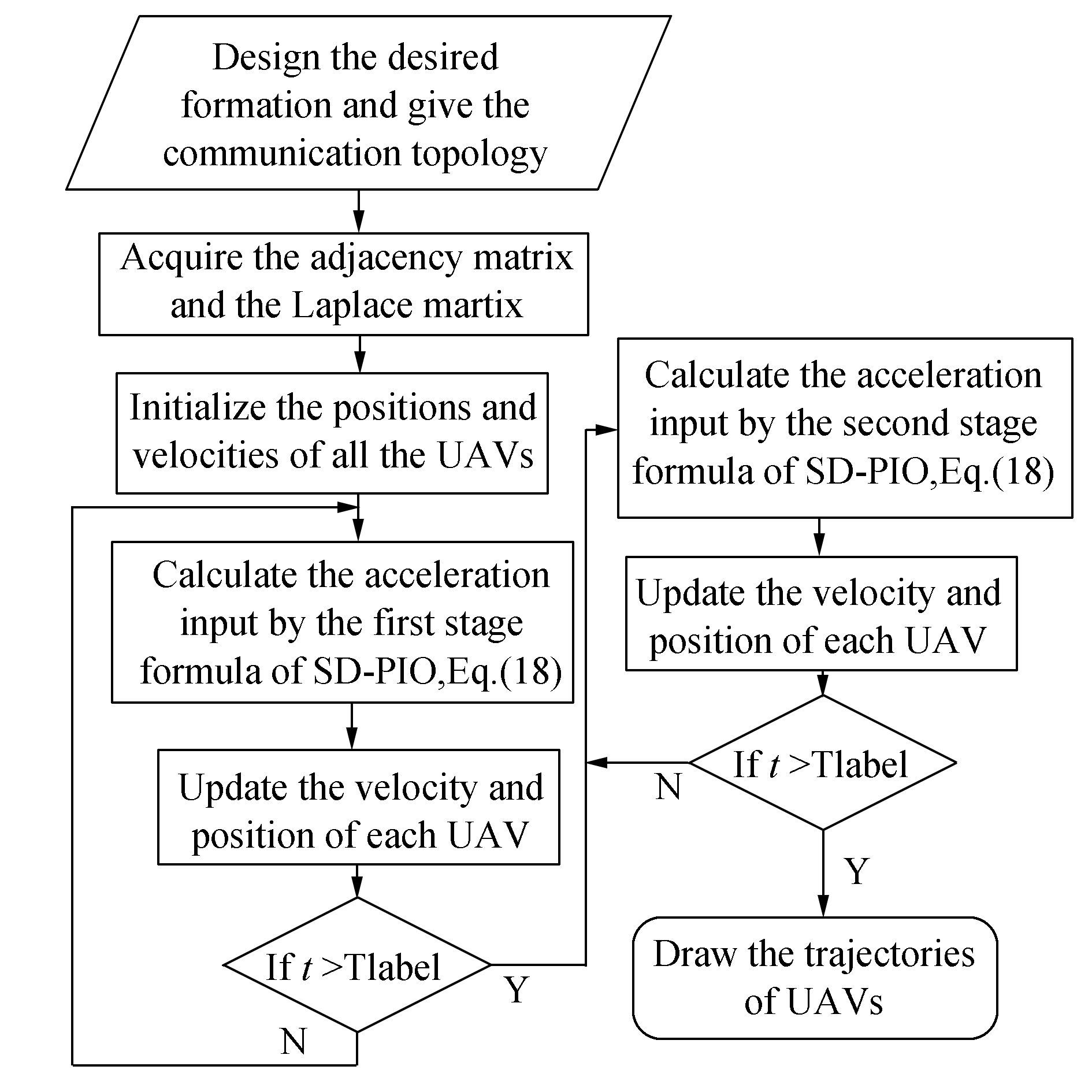
1) Input the number of UAVs in the formation task, give the expectation formation and consider the communication restriction.
2) Design a suitable communication network topology and acquire its adjacency matrix and the Laplace matrix.
3) Randomly initialize the positions and velocities of all the UAVs along with the parameters involved in the equations used in Eq. (18).
4) Calculate the acceleration input, consensus, and the velocity input using Eq. (18)
5) Update each UAV's position and velocity using Eq. (18)
6) Draw the UAV's trajectory according to its position in each iteration.
The process is summarized in the following process flow chart:
|
Figure 4 The process of the SD-PIO based consensus algorithm for a multi-UAV formation |
To validate the SD-PIO-based consensus, numerical simulations were conducted using MATLAB 2012a on a PC with an i5-480 m, 2.67 GHz CPU and Windows 10 operating system. SD-PIO was compared with consensus itself and consensus with two other optimizations, particle swarm optimization (PSO) and PIO. The results prove the effectiveness of SD-PIO.
The main parameters in Eqs. (7), (9), and (18) are listed in Table 2 below. The time step for the simulation is T=0.05 s.
|
|
Table 2 Simulation parameters |
Nine UAVs were initialized with random positions in a 3-dimensional environment as shown in Table 3.
|
|
Table 3 Initial positions of 9 UAVs |
These heights, the numbers on the z-axis, are relative positions corresponding to the height of origin of the common moving coordinate system in Fig. 2. Each UAV had the same initial position in the four simulations, i.e., consensus, PSO-based consensus, PIO-based consensus, and SD-PIO-based consensus.
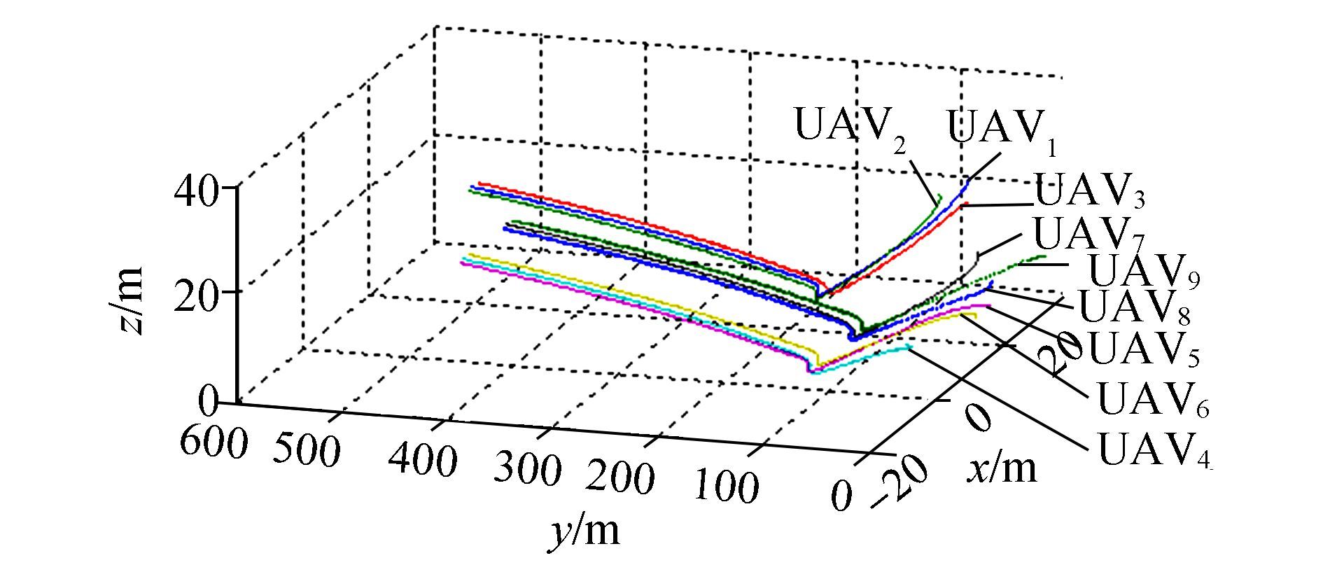
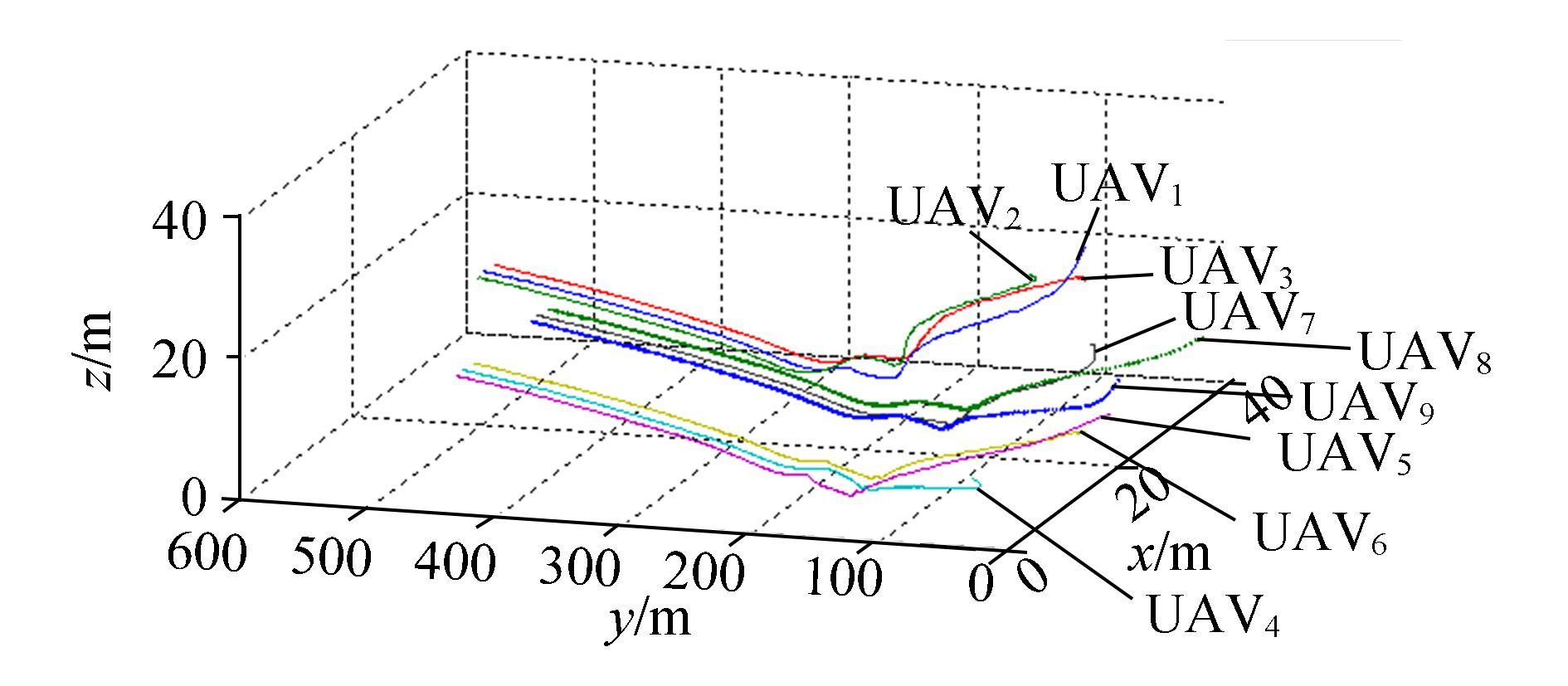
As known from Sections 2 and 3, the performance of consensus cannot satisfy the requirements, which is clearly displayed in Fig. 5. Because of communication restrictions and lack of forecasting, all the UAVs tend to dive sharply and climb quickly. This causes great overload at the turning point, which may damage the UAV's structure and result in difficulties for flight control. Their routes seem to tie a knot when viewed from this perspective, however, it is important to clarify the fact that the trajectories do not cross and the UAVs do not crash in the sky.
|
Figure 5 Trajectories of 9 UAVs by consensus |
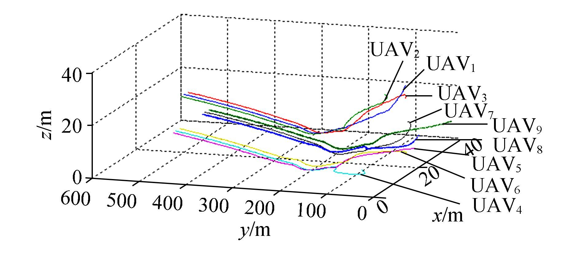
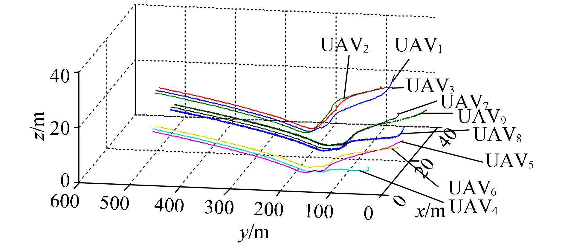
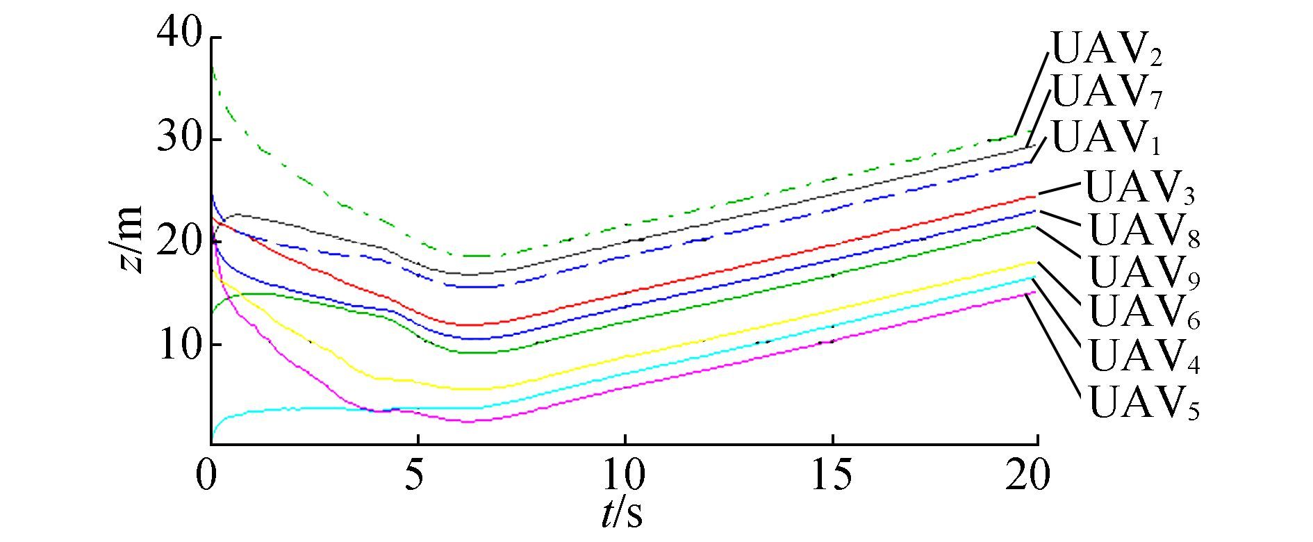
To demonstrate the advantage of SD-PIO-based consensus, PSO-and PIO-based consensus algorithms were adopted to compare their performances with that of the modified algorithm. In Fig. 6, most trajectories are apparently better than those in Fig. 5, as the trajectories are gentle at the beginning and turn without diving sharply. UAV3, UAV5, andUAV9 serve as a set of convincing simulations that support the conclusions above. In Figs. 7 and 8, PIO and SD-PIO work and further improve the performance. In Fig. 7, the overshoot almost disappears, but there is still fluctuation in the trajectories from this perspective, especially for UAV3, UAV4, and UAV5. In Fig. 8, the trajectories become much smoother and the overshoot can be ignored compared with Figs. 5 to 7. This is reflected in the lowest parts of the trajectories of UAV3, UAV4, and UAV5.
|
Figure 6 Trajectories of 9 UAVs by PSO-based consensus |
|
Figure 7 Trajectories of 9 UAVs by PIO-based consensus |
|
Figure 8 Trajectories of 9 UAVs by SD-PIO-based consensus |
The effect of the SD-PIO-based consensus can be analyzed according to the x and z trajectories, but the y trajectory by consensus is smooth enough and does not need improvement. In Figs. 9 and 10, oscillation is more obvious than the counterparts in Figs. 11 and 12. The undesirable trajectories in Fig. 11 partly explain the shortcomings of PIO.
|
Figure 9 X trajectory of 9 UAVs by consensus |

|
Figure 10 X trajectories of 9 UAVs by PSO-based consensus |
|
Figure 11 X trajectories of 9 UAVs by PIO-based consensus |
|
Figure 12 X trajectories of 9 UAVs by SD-PIO-based consensus |
The performance of the x trajectories can be evaluated using change of direction as the criterion. After starting, if a UAV flies along a smooth trajectory towards the desired one without turning, it must have chosen the best and straightest trajectory. An undesirable trajectory leads the UAV into making frequent turns, which costs too much energy and increases the probability of collision.
The X trajectories in Figs. 9 and 10 belong to the undesirable type. In Fig. 9, the trajectories of UAV2, UAV4, and UAV7 curve during flight and each of them turns twice or even three times. UAV2 flies in the direction in which x becomes larger, however at nearly t=1 s, x begins to decrease, then at nearly t=3.5 s, x increases again and meets the desired value at t=5 s. This conflict process can be explained by its topology. In Fig. 3, UAV2 is deeply influenced by UAV1 and UAV3. Unfortunately, all its neighbors start at positions further along the x-axis, which means that UAV2 has to catch up with its neighbor by consensus without reaching its desired positions. Only when its leader realizes they have deviated from the right position, do they begin to correct it. This is a result of a lack of forecasting. However, if UAV2 can directly receive information from UAV10, perhaps it can perform better. This is the limit of communication. These two shortcomings illustrate the necessity for improvement.
In Fig. 10, the situation is not any better. UAV3, UAV4, UAV5, and UAV8 have the same problem. For example, UAV8 starts at x=24.806 m at t=0, then x=21.5 m at nearly t=2 s, then x=25.1 m at nearly t=6 s and decreases to x=18.3 m at t=8 s; the real trajectory goes up and down frequently. This implies PSO cannot satisfy the demand of performance improvement.
In Figs. 11 and 12, fluctuation weakens and the trajectories become much smoother. Most UAVs can fly directly towards their destinations at t=7 s. In Fig. 11, the x position of UAV5 decreases quickly from the beginning to t=5 s, this fast slide slip spoils the performance as it causes a sliding movement of a flying UAV and makes it harder to control.
In Fig. 12, most trajectories are pleasant and suitable as commands for multi-UAV formations.
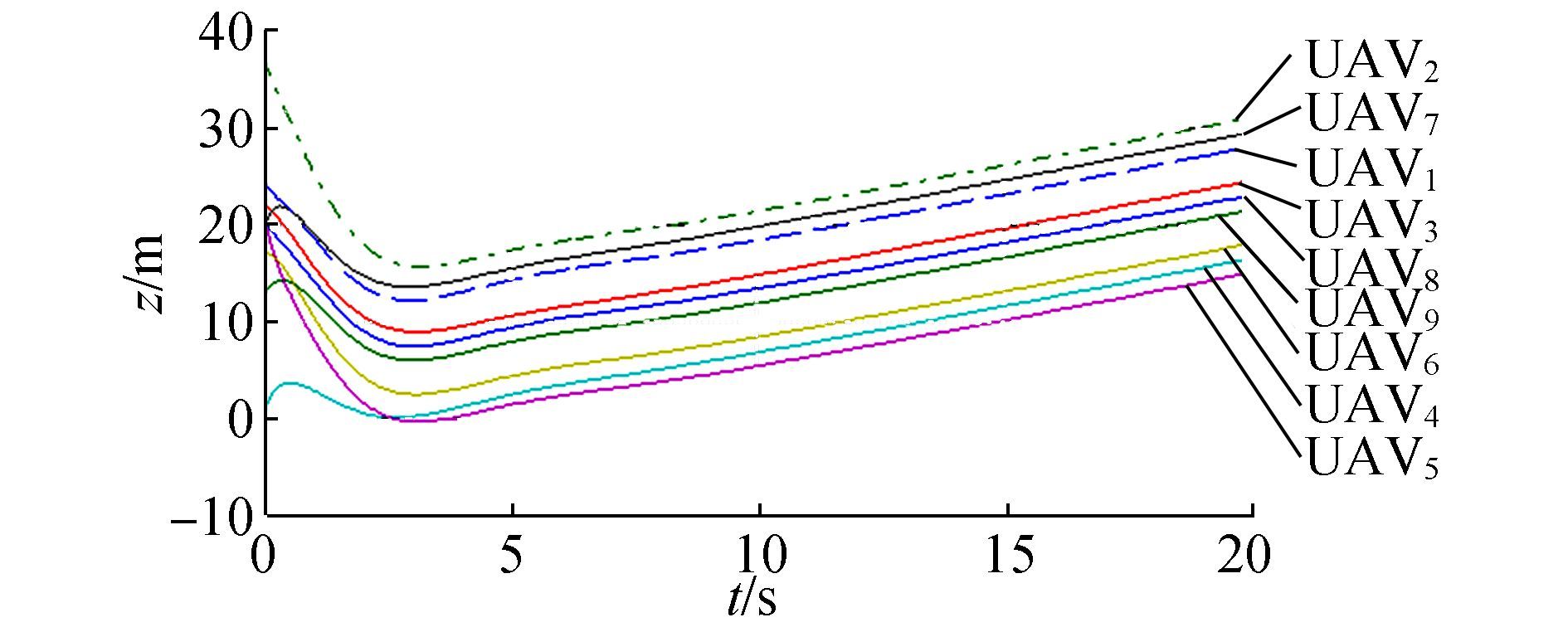
Performance of the z trajectories can be evaluated by the following criterion: diving slowly and never flying up and down. In Fig. 13, all the trajectories quickly go down before t=4 s, this means that the UAVs dive sharply in the beginning, as shown in Fig. 5. The aim of this work is to overcome this shortcoming.

|
Figure 13 Z trajectories of 9 UAVs by consensus |
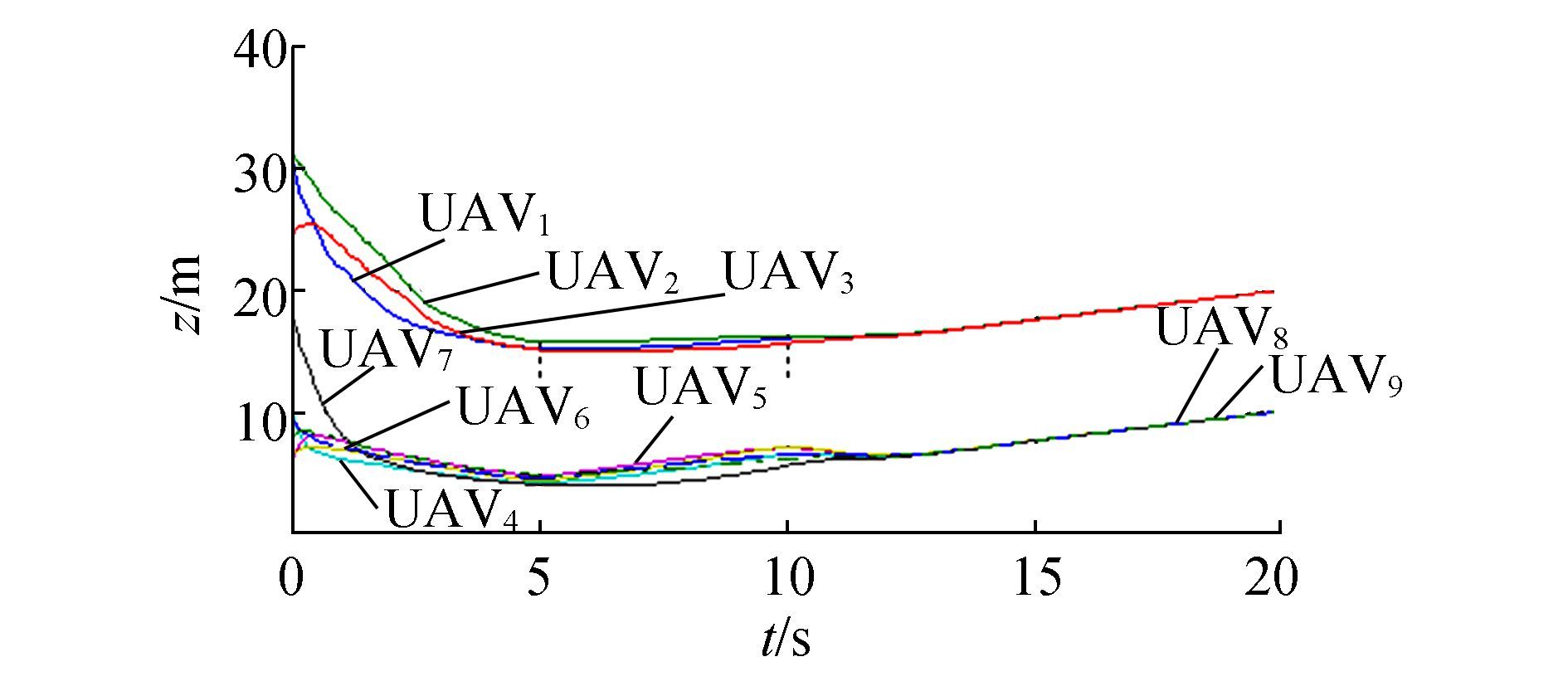
The trajectories in Fig. 14 clarify the advantage of PSO-based consensus because the modified algorithm can effectively reduce oscillation. UAV2 and UAV8 clarify UAV8 this view as they both slowly decrease their height following the desired trajectory instead of diving down swiftly.
|
Figure 14 Z trajectories of 9 UAVs by PSO-based consensus |
However, reduplicative climb and dive still exist, which may induce oscillation. The dangerous trajectories of UAV3 and UAV5 at UAV5 t∈[0, 10]s in Fig. 14 reveal that they are not the desired ones that descend slowly at the beginning, then converge to the desired trajectory. This is why there is great demand for another optimizer.
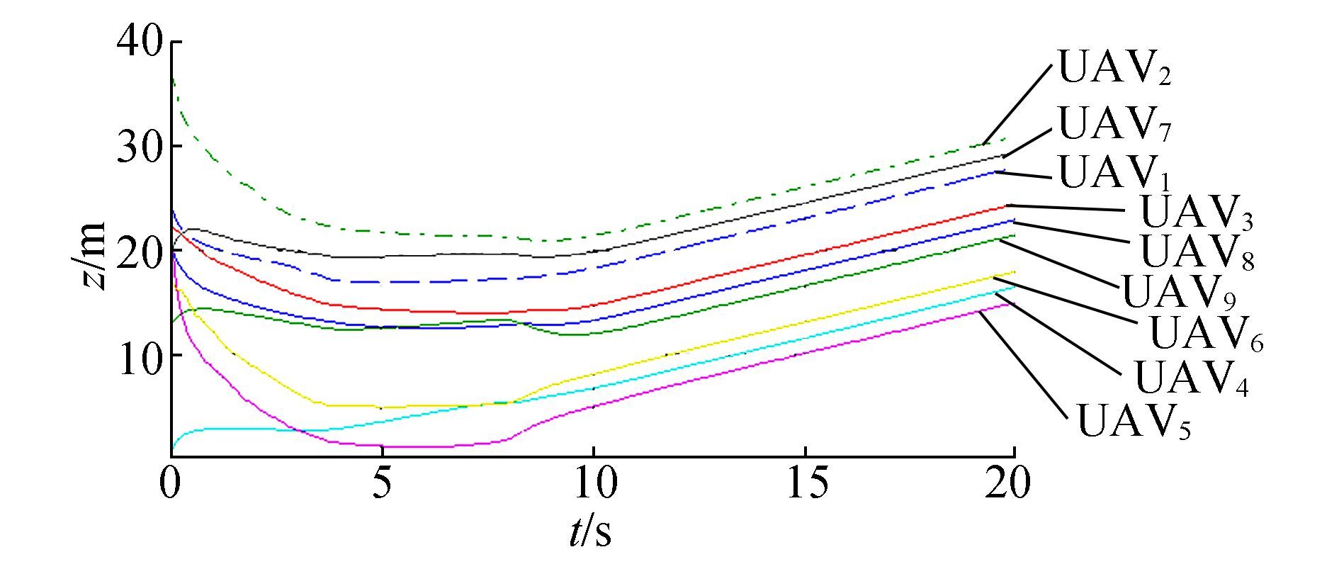
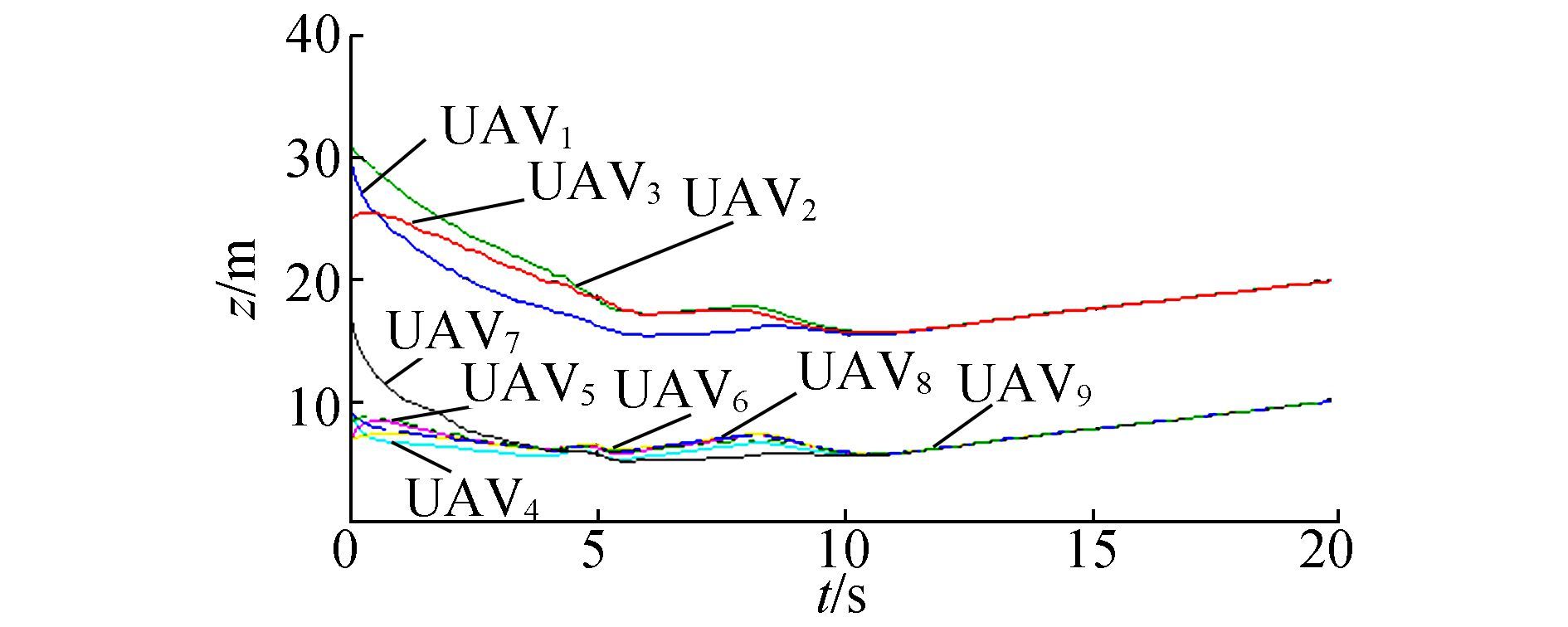
In Fig. 15, PIO is used to apply a gliding procedure. Before 4s, the map and compass operator takes effect and all the UAVs fly towards the best local position. In the time range, 4 to 6 s, the landmark operator drives the UAVs nearby to the same height. When all of them fly to the standard height, the PIO part stops working and consensus continues concentrating the UAVs and guiding them to fly along the designed trajectory.
|
Figure 15 Z trajectories of 9 UAVs by PIO-based consensus |
|
Figure 16 Z trajectories of 9 UAVs by SD-PIO-based consensus |
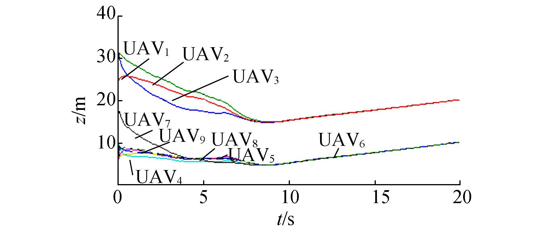
The SD-PIO-based consensus algorithm also follows the steps above, but the difference occurs in the first 8 s as the UAVs descend more slowly and smoothly. UAV1, UAV2 and UAV3 can support this opinion, as they at the same respective height, but at t=5 s, UAV2 and UAV3 by SD-PIO are above 20 m while their counterparts are clearly lower. At t=7 s, the height of UAV1 by SD-PIO is 16.04 m and the outcome by PIO is only 15.47 m.
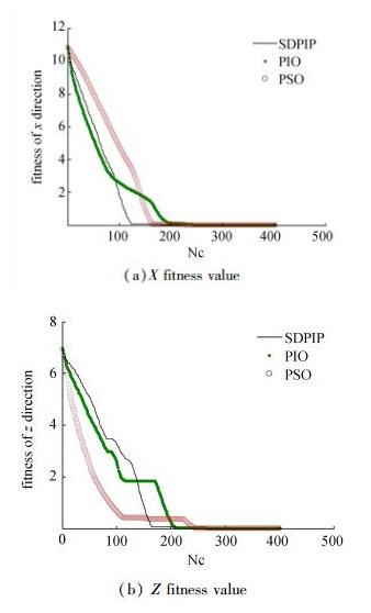
From the fitness function Eq. (8), the closer the UAViapproaches its desired location, the smaller the fitness value. In Fig. 17, as iteration Nc increases, average fitness values decrease and finally approach zero, and different optimizers possess different convergence rates. In Fig. 17(a), PIO shows the fastest speed in the beginning, SD-PIO is a bit slower and PSO shows the weakest performance of the three. However, after Nc= 80, PIO becomes slow and is finally overtaken by SD-PIO at Nc= 93. The poor efficiency of PIO is due to the inadequate local optimum.
|
Figure 17 Fitness value in SD-PIO-based consensus |
In Fig. 17(b), all the fitness values show a tendency to decrease and SD-PIO is the slowest at the beginning. This problem is attributed to the effect of the slow diving strategy itself.
In order to avoid diving sharply, each UAV learns from its neighbor with the smallest velocity on the z-axis in Eq. (11), so the distance error between the desired position and the real one decreases at a slower rate. The UAVs performance and the efficiency of the algorithm have to be a compromise. But SD-PIO successfully eliminates the wrong local optimum and reaches a small value at Nc=167. This clearly reflects the advantage of our improvement as PSO and PIO are trapped at Nc=118. The two platforms in Fig. 17(b) demonstrate the local optimum and the algorithms temporarily stop evolution. However, all three optimizers manage to find the global minimum after Nc=270.
5 Conclusions and future worksIn this paper, consensus for multi-UAV formations is improved with a modified SD-PIO formula. PIO and PSO are adopted to optimize consensus for better performance of the initial flight trajectory. The method effectively reduces oscillation and smooths the curves. Consensus takes into effect subsequent responses and ensures that all the UAVs converge to the standard path. The combination of the two algorithms is proved to be useful for the multi-UAV formation problem.
Our future work will focus on the optimization of consensus. The method introduced is perhaps not the best choice and there is still room to explore better optimizations. However, the outstanding advantage of consensus is its distributed features, as most optimization methods demand global information. How to combine them while retaining their individual advantages remains a challenge.
| [1] |
RYAN A, ZENNARO M, HOWELL A, et al. An overview of emerging results in cooperative UAV control[C]//The proceedings of 43rd IEEE Conference on Decision and Control. atlantis, Paradise Island, Bahamas, 2004: 602-607
(  0) 0)
|
| [2] |
ZHA W, CHEN J, PENG Z. Dynamic multi-team antagonistic games model with incomplete information and its application to multi-UAV[J]. IEEE/CAA Journal of automatica sinica, 2015, 2(1): 74-84. DOI:10.1109/JAS.2015.7032908 (  0) 0)
|
| [3] |
CHAUMETTE S, LAPLACE R, MAZEL C. CARUS, an operational retasking application for a swarm of autonomous UAVs: first return on experience[C]//The proceedings of 2011 Military Communications Conference Track 5 Communications and Network Systems. Baltimore, Maryland, USA, 2011: 2003-2010.
(  0) 0)
|
| [4] |
RASCHE C, STERN C, KLEINJOHANN L, et al. A distributed multi-UAV path planning approach for 3D environments[C]//The proceedings of the 5th International Conference on Automation, Robotics and Applications. Wellington, New Zealand, 2011: 7-12.
(  0) 0)
|
| [5] |
GIULIETTI F, INNOCENTI M, NAPOLITANO M, et al. Dynamic and control issues of formation flight[J]. Aerospace science and technology, 2005, 9(1): 65-71. DOI:10.1016/j.ast.2004.06.011 (  0) 0)
|
| [6] |
CRUZ J. Leader-follower strategies for multilevel systems[J]. IEEE transactions on automatic control, 1978, 23(2): 244-255. DOI:10.1109/TAC.1978.1101716 (  0) 0)
|
| [7] |
PAUL T, KROGSTAD T, GRAVDAHL J. Modelling of UAV formation flight using 3D potential fields[J]. Simulation modelling practice and theory, 2008, 16(9): 1240-1254. (  0) 0)
|
| [8] |
RAO V, SINHA N. A sliding mode controller for aircraft simulated entry into spin[J]. Aerospace science and technology, 2013, 8(1): 154-163. (  0) 0)
|
| [9] |
REN W, BEARD R, ATKINS E. Information consensus in multivehicle cooperative control:collective group behavior through local interaction[J]. IEEE control systems, 2007, 27(2): 71-82. DOI:10.1109/MCS.2007.338264 (  0) 0)
|
| [10] |
VICSEK T. Universal patterns of collective motion from minimal models of flocking[C]//The proceedings of the 2nd IEEE International Conference on Self-Adaptive and Self-Organizing Systems. Venice, Italy, 2008: 3-11.
(  0) 0)
|
| [11] |
REN W, BEARD R W, MCLAIN T W. Coordination variables and consensus building in multiple vehicle systems[J]. Lecture notes in control and information sciences, 2005, 309: 439-442. (  0) 0)
|
| [12] |
REN W, BEARD R W. Consensus seeking in multiagent systems under dynamically changing interaction topologies[J]. IEEE transactions on automatic control, 2005, 50(5): 655-661. DOI:10.1109/TAC.2005.846556 (  0) 0)
|
| [13] |
SORENSEN N, REN W. A unified formation control scheme with a single or multiple leaders[C]//The proceedings of American Control Conference. New York City, USA, 2007: 5412-5418.
(  0) 0)
|
| [14] |
REN W, SORENSEN N. Distributed coordination architecture fo r multi-robot formation control[J]. Robotics and autonomous systems, 2008, 56(4): 324-333. DOI:10.1016/j.robot.2007.08.005 (  0) 0)
|
| [15] |
DUAN H, QIAO P. Pigeon-inspired optimization:a new swarm intelligence optimizer for air robot path planning[J]. International journal of intelligence computation and cybernetics, 2014, 7(1): 24-37. DOI:10.1108/IJICC-02-2014-0005 (  0) 0)
|
| [16] |
GUILFORD T, ROBERTS S, BIRO D, et al. Positional entropy during pigeon homing Ⅱ:navigational interpretation of Bayesian latent state models[J]. Journal of theoretical biology, 2004, 227(1): 25-38. DOI:10.1016/j.jtbi.2003.07.003 (  0) 0)
|
| [17] |
LI C, DUAN H. Target detection approach for UAVs via improved pigeon-inspired optimization and edge potential function[J]. Aerospace science and technology, 2014, 39: 352-360. DOI:10.1016/j.ast.2014.10.007 (  0) 0)
|
| [18] |
ZHANG B, DUAN H. Three-dimensional path planning for uninhabited combat aerial vehicle based on predator-prey pigeon-inspired optimization in dynamic environment[J]. IEEE/ACM transactions on computation and biology bioinformaion, 2017, 14(1): 97-107. DOI:10.1109/TCBB.2015.2443789 (  0) 0)
|
| [19] |
DUAN H, WANG X. Echo state networks with orthogonal pigeon-inspired optimization for image restoration[J]. IEEE transactions on neural networks and learning Systems, 2016, 27(11): 2413-2425. DOI:10.1109/TNNLS.2015.2479117 (  0) 0)
|
| [20] |
ZHANG S, DUAN H. Gaussian Pigeon-inspired optimization approach to orbital spacecraft formation reconfiguration[J]. Chinese journal of aeronautics, 2015, 28(1): 200-205. DOI:10.1016/j.cja.2014.12.008 (  0) 0)
|
| [21] |
ZHAO J, ZHOU R. Pigeon-inspired optimization applied to constrained gliding trajectories[J]. Nonlinear dynamics, 2015, 82(4): 1781-1795. DOI:10.1007/s11071-015-2277-9 (  0) 0)
|
 2017, Vol. 12


