2. 贵州高峰石油机械股份有限公司;
3. 青岛金江源工业装备有限公司;
4. 中国石油集团川庆钻探工程有限公司长庆钻井总公司
2. Guizhou Gaofeng Petroleum Machinery Co., Ltd.;
3. Qingdao Jinjiangyuan Industrial Equipment Co., Ltd.;
4. Changqing Drilling Company, CNPC Chuanqing Drilling Engineering Company Limited
0 引言
CD-GF型钻井球阀是一种位于顶部驱动钻井系统下端的重要构件,其作用是对钻井液实施导通、节流和阻闭。CD-GF型钻井球阀的载荷工况十分恶劣,承受石油钻井过程中拉、扭、内压等3大重型载荷[1-3]。其中,拉力载荷为整体钻柱的重力,扭矩载荷为顶驱系统的输出扭矩,内压载荷为钻井泵的额定工作压力。阀体是上述3大载荷的交汇作用点,且其几何结构最为薄弱,其外壳的开孔部位时常出现开裂破坏现象,影响钻井作业的正常进行。因此,有必要对钻井球阀阀体的受力特性进行详细的分析计算和试验研究。
本文针对CD-GF型钻井球阀阀体,建立了有限元静动力学计算模型,运用ANSYS Workbench软件求解,得到不同结构阀体在复杂载荷工况下的最大应力和总变形量,并对其进行比较分析,在保证阀体强度和刚度的前提下,尽可能减小其局部应力集中与总变形量,使其结构更为合理[3]。本文重点研究阀体单边开孔、双边对称开孔和内部尺寸微调等多种方案条件下,阀体的最大应力和最大变形量的变化情况,以期为钻井球阀阀体的结构优化与改进提供基础数据。
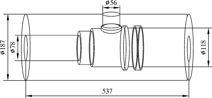
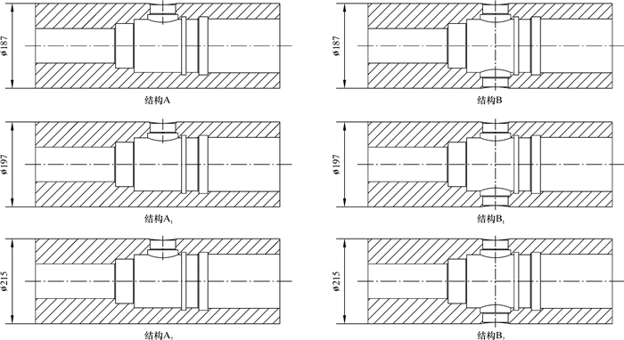
1 模型建立根据CD-GF型钻井球阀的工作原理与实际工况,建立计算模型(见图 1)。考虑在实际装配过程中要保证阀体的内径不变,因此提出6种阀体的结构方案,具体如图 2所示。

|
| 图 1 CD-GF型钻井球阀计算模型 Fig.1 Calculation model of the CD-GF type drilling ball valve |

|
| 图 2 6种阀体结构方案 Fig.2 Schematic diagram of six kinds of valve body structures |
结构A:基础阀体,即单边开孔方案。
结构A1:基础阀体+外径增大10 mm方案,即在结构A的基础上将阀体外径由187 mm改为197 mm。
结构A2:基础阀体+外径增大28 mm方案,即在结构A的基础上将阀体外径由187 mm改为215 mm。
结构B:基础阀体+双边开孔方案,即在结构A的另一侧壁对称开孔,新开孔与原孔以轴线对称且大小相同。
结构B1:外径增大10 mm方案+双边开孔方案,即为结构A1与结构B的综合。
结构B2:外径增大28 mm方案+双边开孔方案,即为结构A2与结构B的综合。
2 网格划分实体模型建好后,需要对其划分网格。以原阀体结构为例,按以下方法对其进行智能网格划分:①由于阀体尺寸较大,对其整体划分网格,尺寸为20 mm。②为了精确分析阀体开孔附近的应力应变[4],宜对开孔部位进行二次网格划分,网格尺寸为5 mm。③最终节点数为21 190个,单元数为11 902个(见图 3)。阀体材料采用4330V-MOD合金钢,材料特性为各向同性,其基本性能参数如表 1所示。

|
| 图 3 网格划分 Fig.3 Mesh generation |
| 弹性模量/GPa | 泊松比 | 密度/(kg·m-3) | 抗拉强度/MPa | 屈服强度/MPa | 伸长率/% |
| 210 | 0.3 | 8.25×10³ | ≥1 140 | ≥1 030 | ≥15 |
3 加载与约束
根据GB/T 31049—2014《石油钻机顶部驱动钻井装置》[5]、SY 5138—1992《三缸单作用钻井泵》[6]、SY/T 5080—2013《石油钻机和修井机用转盘》[7]中相关技术要求,结合钻井过程中的实际工况,对钻井球阀阀体有限元模型采用拉伸、扭转和内压综合作用下的组合载荷加载[8-16],其载荷等级见表 2。另外,实际建模计算时,对阀体下端面施加固定约束,对阀体上端面施加拉力载荷,对阀体外表面施加扭矩载荷,在阀体内面施加内压载荷。
| 名称 | 拉力/kN | 内压/MPa | 扭矩/(kN·m) |
| 数值 | 2 250、3 150、4 500 | 32.6、33.1、35.6、37.7、42.1 | 27.459、32.365、36.285 |
4 模拟结果与分析 4.1 拉力对阀体最大应力与总变形量的影响
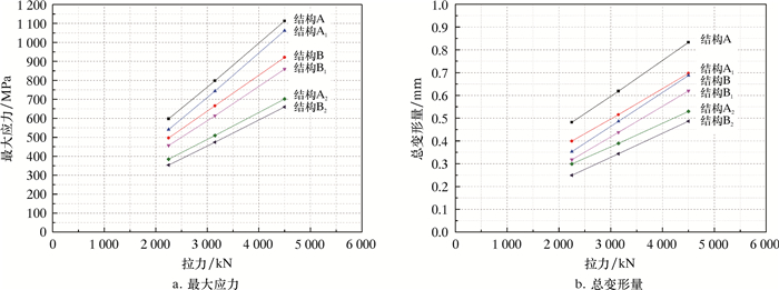
当内压为32.6 MPa、工作扭矩为27.459 kN·m时,改变拉力(2 250、3 150和4 500 kN),分别建模和计算6种阀体结构的最大应力与总形变量。不同拉力作用下阀体应力云图与位移云图如图 4所示,阀体最大应力与总形变量随拉力变化的曲线如图 5所示,结果对比如表 3所示。

|
| 图 4 不同拉力作用下阀体的应力云图与位移云图 Fig.4 Stress and displacement distribution of the valve body under different tensile forces |

|
| 图 5 不同拉力作用下6种阀体最大应力与总变形量的变化曲线 Fig.5 The maximum stress and total deformation of six kinds of valve bodies under different tensile forces |
| 项目 | 平均变化率/% | ||||
| A1相对A | A2相对A | B相对A | B1相对A | B2相对A | |
| 最大应力 | -16.5 | -36.2 | -7.2 | -23.1 | -40.7 |
| 总变形量 | -16.7 | -37.1 | -21.8 | -29.6 | -44.8 |
由图 4可以看出:CD-GF型钻井球阀阀体受力后的最大应力部位均相同,在侧壁孔附近的应力集中现象比较严重,都在与球阀阀体轴线垂直的孔壁上,是整个球阀阀体的薄弱点;阀体总变形量在下端面最小,在上端面最大,并且在上端面边缘处有最大值。
由图 5可知,在不同的拉力作用下,阀体的最大应力和总变形量随拉力的增加而增大,且呈线性关系。
由表 3可以看出:相对于原阀体结构A,其他5种方案(A1、A2、B、B1、和B2)均能有效地减小阀体的应力集中与总变形量;结构B2的效果最好,结构B2相对于原阀体结构A在最大应力上减少的平均值为40.7%,总形变量减少的平均值为44.8%。
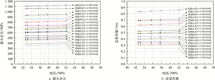
4.2 内压对阀体最大应力与总变形的影响在工作扭矩27.459 kN·m不变的情况下,改变内压(32.6、33.1、35.6、37.7和42.1 MPa)和拉力(2 250、3 150和4 500 kN),模拟计算6种阀体的最大应力与总变形量。不同内压与拉力作用下阀体应力云图与位移云图如图 6所示,不同拉力下阀体的最大应力与总变形量随内压变化曲线如图 7所示,结果对比如表 4所示。

|
| 图 6 不同内压与拉力作用下阀体的应力云图与位移云图 Fig.6 Stress and displacement distribution of valve body under different internal pressure and tensile forces |

|
| 图 7 不同内压与拉力下6种阀体最大应力与总变形量的变化曲线 Fig.7 The maximum stress and total deformation of six kinds of valve bodies under different internal pressure and tensile forces |
| 项目 | 平均变化率/% | ||||
| A1相对A | A2相对A | B相对A | B1相对A | B2相对A | |
| 最大应力 | -16.3 | -35.9 | -7.8 | -23.3 | -40.6 |
| 总变形量 | -16.8 | -37.3 | -23.2 | -30.8 | -45.7 |
由图 6和图 7可以看出:在不同的拉力与内压作用下,钻井球阀阀体的最大应力与总变形量均随拉力、内压的增加而增加,并且呈线性关系;拉力是其变化的主要影响因素,内压是其变化的次要影响因素。
由表 4可知:相对于原阀体结构A,其他5种方案(A1、A2、B、B1和B2)均能有效减小阀体的应力集中与总变形量;结构B2的效果最好,结构B2相对于原阀体结构A在最大应力上减少的平均值为40.6%,总变形量减少的平均值为45.7%。
4.3 工作扭矩对阀体最大应力与总变形的影响在内压32.6 MPa不变的情况下,改变工作扭矩(27.459、32.365和36.285 kN·m)和拉力(2 250、3 150和4 500 kN),模拟计算6种阀体的最大应力与总变形量。不同工作扭矩和拉力作用下阀体应力云图与位移云图如图 8所示,不同拉力下阀体的最大应力与总变形量随工作扭矩变化的曲线如图 9所示,结果对比如表 5所示。

|
| 图 8 不同工作扭矩与拉力下阀体的应力云图与位移云图 Fig.8 Stress and displacement distribution of the valve body under different torques |

|
| 图 9 不同扭矩与拉力下6种阀体最大应力与总变形量的变化曲线 Fig.9 The maximum stress and total deformation of six kinds of valve bodies under different torque and tensile forces |
| 项目 | 平均变化率/% | ||||
| A1相对A | A2相对A | B相对A | B1相对A | B2相对A | |
| 最大应力 | -16.6 | -36.3 | -7.1 | -23.2 | -40.7 |
| 总变形量 | -16.8 | -37.3 | -22.1 | -29.9 | -45.0 |
由图 8和图 9可知:在不同拉力与工作扭矩作用下,阀体的最大应力与总变形量均随拉力、工作扭矩的增加而增加,且呈线性关系;拉力是其变化的主要影响因素,工作扭矩是其变化的次要影响因素。
由表 5可知:相对于原阀体结构A,其他5种方案(A1、A2、B、B1和B2)均能有效减小阀体的应力集中与总变形量;结构B2的效果最好,结构B2相对于原阀体结构A在最大应力上减少的平均值为40.7%,总变形量减少的平均值为45.0%。
4.4 拉力极限分析当内压为32.6 MPa、工作扭矩为27.459 kN·m时,改变拉力,计算不同阀体在材料屈服极限1 030 MPa下的最大拉力,计算结果如表 6所示。
| 阀体结构 | A | A1 | A2 | B | B1 | B2 |
| 拉力 | 4 200 | 4 400 | 6 800 | 5 000 | 5 400 | 7 150 |
5 结论
(1) 运用ANSYS Workbench软件对6种CD-GF型钻井球阀阀体进行了多种工况组合的有限元分析,计算结果表明:在阀体孔边附近存在一定的应力集中现象,最大应力点出现在与阀体轴线垂直的孔壁上;随着与圆孔区域距离的增大,其应力值减小。阀体的最大应力小于其材料的极限抗拉强度,其力学行为仍然处于弹性变形阶段。
(2) 随着拉力、内压、工作扭矩的增加,阀体最大应力与总变形量也增大,其中拉力对其影响最大,内压与工作扭矩对其影响相对较小,即拉力载荷是影响其强度的主控因素。
(3) 相对于原阀体结构A,其他5种方案(A1、A2、B、B1和B2)均能有效减小阀体的应力集中与总变形量,其中,以结构B2(外径增大28 mm+双边开孔方案)的效果最好。
(4) 由于拉力载荷是影响阀体强度的主控因素,所以计算出6种阀体在材料屈服极限下的极限拉力。计算结果可为不同阀体在钻进过程中的使用范围提供参考。
| [1] |
张武辇, 贾银鸽, 张静, 等. 阀式连续循环钻井装置的工业化应用探讨[J]. 石油钻采工艺, 2014, 36(6): 1-6. ZHANG W N, JIA Y G, ZHANG J, et al. Discussion on industrial application of valve type continuous circulation drilling device[J]. Oil Drilling&Production Technology, 2014, 36(6): 1-6. |
| [2] |
冯定, 于章丽, 夏成宇, 等. 气体钻井连续循环短节主通阀的设计与分析[J]. 石油机械, 2014, 42(8): 28-32. FENG D, YU Z L, XIA C Y, et al. Design and analysis of main valve of continuous circulation joint for gas drilling[J]. China Petroleum Machinery, 2014, 42(8): 28-32. DOI:10.3969/j.issn.1001-4578.2014.08.007 |
| [3] |
李春吉, 何东升, 谢毅, 等. 一种新型连续循环阀设计[J]. 钻采工艺, 2011, 34(2): 64. LI C J, HE D S, XIE Y, et al. Design of a new type of continuous circulation valve[J]. Drilling&Production Technology, 2011, 34(2): 64. DOI:10.3969/j.issn.1006-768X.2011.02.020 |
| [4] |
许期聪, 邓虎, 周长虹, 等. 连续循环阀气体钻井技术及其现场试验[J]. 天然气工业, 2013, 33(8): 83-87. XU Q C, DENG H, ZHOU C H, et al. Field tests of gas drilling technology with continuous circulation valves[J]. Natural Gas Industry, 2013, 33(8): 83-87. |
| [5] |
全国石油钻采设备和工具标准化技术委员会.石油钻机顶部驱动钻井装置: GB/T 31049-2014[S].北京: 中国标准出版社, 2015: 3-10. China National Technical Committee for Standardization of Drilling Equipment and Tools.Top drive drilling rig equipment for oil drilling rigs: GB/T 31049-2014[S].Beijing: China Standard Press, 2015: 3-10. |
| [6] |
全国石油钻采设备和工具标准化技术委员会.三缸单作用钻井泵: SY 5138-1992[S].北京: 中国标准出版社, 1993: 1-2. National Petroleum Drilling Equipment and Tools Standardization Technical Committee.Three cylinder single action drilling pump: SY 5138-1992[S]. Beijing: China Standard Press, 1993: 1-2. |
| [7] |
全国石油钻采设备和工具标准化技术委员会.石油钻机和修井机用转盘: SY/T 5080-2013[S].北京: 中国标准出版社, 2014: 2-3. China National Technical Committee for Standardization of Drilling Equipment and Tools.Rotary table for petroleum drilling and workover rig: SY/T 5080-2013[S]. Beijing: China Standard Press, 2014: 2-3. |
| [8] |
任灵超, 何东升. 不间断循环阀的设计[J]. 石油机械, 2009, 37(9): 129-132. REN L C, HE D S. Design of continuous cycle valve[J]. China Petroleum Machinery, 2009, 37(9): 129-132. |
| [9] |
梁士锋. 自动再循环阀介绍及选型要点[J]. 石油化工设计, 2016, 33(3): 16-19. LIANG S F. Introduction and type selection of automatic recirculation valve[J]. Petrochemical Design, 2016, 33(3): 16-19. DOI:10.3969/j.issn.1005-8168.2016.03.008 |
| [10] |
张福坤, 艾勇, 王晔. 输气管道球阀结构特点及密封失效原因[J]. 油气储运, 2016, 35(1): 73-77. ZHANG F K, AI Y, WANG Y. Structural features and reasons for seal failure of ball valves in gas pipelines[J]. Oil & Gas Storage and Transportation, 2016, 35(1): 73-77. |
| [11] |
朱喜平, 郭存杰, 付京晶, 等. 长输天然气管道球阀的结构特点与应用[J]. 管道技术与设备, 2008, 36(3): 36-37. ZHU X P, GUO C J, FU J J, et al. Structure feature and application of ball valve for long-distance gas pipelines[J]. Pipeline Technique and Equipment, 2008, 36(3): 36-37. DOI:10.3969/j.issn.1004-9614.2008.03.015 |
| [12] |
高洪波, 秦丰高, 徐孙见. 浅析天然气管道球阀阀体选型及运行对策[J]. 科学与财富, 2016(31): 680. GAO H B, QIN F G, XU S J. Analysis on the selection of valve body of natural gas pipeline and its operation countermeasures[J]. Science and Fortune, 2016(31): 680. |
| [13] |
方本孝, 杨信平. 阀门密封性能的研究[J]. 阀门, 1999(2): 12-16. FANG B X, YANG X P. Study on valve sealing performance[J]. Valve, 1999(2): 12-16. |
| [14] |
姜子龙, 郭睿, 安黎. 天然气管道球阀的结构特点及使用的注意事项分析[J]. 智能城市, 2016(3): 253. JIANG Z L, GUO R, AN L. Analysis of structural characteristics and precautions for use of natural gas pipeline ball valves[J]. Intelligent City, 2016(3): 253. |
| [15] |
贾振发, 贾振山. 天然气输送管道中球阀的应用技术概述[J]. 黑龙江科学, 2014, 5(7): 252. JIA Z F, JIA Z S. Application of ball valve in natural gas pipeline[J]. Heilongjiang Science, 2014, 5(7): 252. DOI:10.3969/j.issn.1674-8646.2014.07.217 |
| [16] |
江帆, 岳鹏飞, 黎斯杰, 等. 水环稠油运输中的球阀内流动结构数值模拟[J]. 石油机械, 2017, 45(4): 107-112. JIANG F, YUE P F, LI S J, et al. Numerical simulation of flow structure in ball check valve in water ring heavy oil transportation[J]. China Petroleum Machinery, 2017, 45(4): 107-112. |


