文章信息
- 郑加强, 贾志成, 周博, 周宏平
- , Zheng Jiaqiang, Jia Zhicheng, Zhou Bo, Zhou Hongping, Zhu Heping
- 基于动态树木图像序列的实时拼接系统及其深度信息检测
- Real-Time Mosaicing System and Distance Detection Based on Dynamic Tree Image Sequence
- 林业科学, 2014, 50(5): 82-89
- Scientia Silvae Sinicae, 2014, 50(5): 82-89.
- DOI: 10.11707/j.1001-7488.20140511
-
文章历史
- 收稿日期:2013-05-22
- 修回日期:2013-12-31
-
作者相关文章
2. 美国农业部ARS 应用技术研究中心 OH 44691, USA
2. USDA/ARS Application Technology Research Unit, Wooster, OH 44691, USA
Ornamental shade trees are used to beautify the l and scape and served as wind barriers. These trees are usually planted singly at a site and consequently are susceptible to be attacked by insects and diseases. Applications of foliar pesticides are an economic and effective control measure to protect these trees from the pest damages. However,spray applications presents special problems because the locations of these trees are usually near residential areas,commercial districts,industrial and recreational parks,water resources or ecological sensitive regions. Conventional spraying systems deliver constant rates of chemicals to these trees regardless of tree size,shape and foliage density as well as the spacing between trees. Thus,a large portion of the pesticide is wasted on non-targeted areas(Zheng et al.,2006). Sensor technologies to detect trees and their configurations and minimize off-target losses of chemicals for target-oriented spraying systems are needed when spraying these trees.
However,target-oriented sprayers have great difficulties to maintain a consistent distance between the sprayer nozzle and the target trees because these trees may have r and om positions. Also,for tall trees the sprayers should have adequate distance away from the trees to allow sprays to cover the entire tree height. Despite distance variability,to ensure sprays are applied at the proper time after sensors detect target trees,different delay times are required to discharge sprays. That is,the sprayers must calculate the delayed time required between the tree detected and the tree sprayed. Thus,critical to the sprayers is sensors that can detect the target tree and determine its distance from the sprayers for target-oriented spray applications.
Ultrasonic sensors are a type of sensors that have been used to detect trees to control spray applications(Giles et al.,1988; Tumbo et al.,2002; Zaman et al.,2004). Jeon et al.(2011b; 2012)used these sensors to detect the distance between the sprayer and the surface of tree canopy to calculate tree size. However,the detection range of a single ultrasonic sensor is limited. If multiple sensors were used,interference between adjacent sensors would compromise their accuracy(Tumbo et al.,2002; Zaman et al.,2004; Jeon et al.,2011a). Another type of sensor,LIDAR(Light Detection and Ranging)has been used to measure target tree distances and canopy sizes(Chen et al.,2012,Wei et al.,2005; Lee et al.,2008; Rosell Polo et al.,2009),but they are relatively expensive.
Machine vision technology implanting image acquisition systems has been widely used to detect crops and weeds(Meyer et al.,1998; Hu et al.,2009; Wang et al.,2011; Steward et al.,2002; Tian et al.,1998; Jeon et al.,2011a). In other areas,this technology incorporating stereoscopic mosaicking technique with multi cameras has been used to determine the depth of view for targets in satellite mapping(Song et al.,2003; Bignalet-Cazalet et al.,2010),marine survey(Nagahdaripour,1998; Rzhanov et al.,2000),remote sensing practice(Bielski et al.,2007; Joshi et al.,2010),medical devices for clinical diagnosis(Miranda-Luna et al.,2008) and other areas(Guestrin et al.,1998).
To achieve target-oriented spraying systems,the Charge-Coupled Device(CCD)technology with image mosaicking technique,which uses one camera to detect trees and measure tree characteristics,has the potential to control spray applications. With this technique,when real-time video images of trees are captured,a set of relative color index is generated to obtain the target tree structure characteristics from the segmentation of target trees and background(Zheng et al.,2005; Zhou et al.,2010). Employing the real-time tree structure information into a control system,a target-oriented sprayer could automatically control spray output based on target needs. However,the use of one camera without a reference target to measure the distance between the camera and trees is a limiting factor(Sawhney et al.,1999). Also,for a tall tree,the images from one camera may not be able to cover the entire tree height if the sprayer is close to the tree.
The use of mosaicking image technique to measure tree distances and increase pesticide spray accuracy for target-oriented sprayers has not been reported. To address these problems,this research proposed a two-camera system to simultaneously capture images of entire trees and then use stereoscopic mosaicking technology to combine these separate images into a new image to obtain the tree structure and distance from the cameras. Thus,the objective of this research was to develop and validate a dynamic tree image mosaicking system derived from a geometrical algorithm based on a configuration of two digital cameras to determine the distance between the target tree and the cameras along with the tree structure.
2 Materials and methods 2.1 Overlapping area of mosaicked tree imagesBinocular stereoscopic vision function states that an object position in three dimensional coordinates can be determined from two perspective images obtained from two angles when the two imaging surfaces form an intersection line. Specially,based on the triangulation principle,the positions of three-dimensional objects could be obtained through the corresponding relationship of the pixels from the two images.
The three dimensional position of the object can be determined by the transformation matrix from the object points in the spatial coordinates to the image coordinate system. In the image mosaicking process,the corresponding points of two images can characterize the relative position of the two images. However,to obtain the object distance information from the images,the first step was to know the relative spatial position of two cameras and its own parameters such as the angle of two camera optical axes,focus distance,and the angle of field-of-view for each camera.
As shown in Fig. 1,when the position of two cameras was assigned,the overlapping area of two images of the same target tree varied with only the distance between the tree and cameras. A shorter distance could have fewer pixels in the overlapping area. The distance information of the target tree could be obtained by calculating the ratio between the height of the overlapping area and the height of two combined images. This ratio is defined as the overlapping coefficient of mosaicked images. If the entire target tree was treated as a plane in the process of image mosaicking,the tree distance was actually the distance between the plane of the target tree and the line across the two focus points of two cameras.
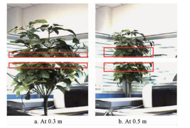 |
Fig. 1 The overlapping area of two images for a target at two
different distances (a) 0.3 m and (b) 0.5 m from the cameras
|
Fig. 2 shows the geometry of relative positions of two cameras to the target tree. Parameters in the geometry are defined as: α for the angle of two camera optical axes,b for the distance between the focus points of two cameras,θ for the field-of-view angle of each camera,D for the distance from the line of two focus points to the target tree plane,H for the visual height of target plane,and L for the height of the overlapping area. When the target plane is projected to the plane that is parallel to the imaging plane,the projected visible height is H',and the projected overlapping height is L',then the overlapping coefficient K should be,
 |
Fig. 2 Geometry of spatial positions of two
cameras and target tree plane
|
| $ K = \frac{{L'}}{{H'}} $ | (1) |
Analyzing the geometry shown in figure 2 yields,
| $ L = \frac{{\cos \left( {\frac{\theta }{2} - \alpha } \right)}}{{\cos \frac{{\theta - \alpha }}{2}}}L', $ | (2) |
| $ H' = \frac{{\cos \left( {\frac{\theta }{2} + \alpha } \right)}}{{\frac{{\cos \theta }}{2}}}H, $ | (3) |
and
| $ H = \frac{{2\sin \theta }}{{\cos \theta + \cos \alpha }}D. $ | (4) |
D actually is the sum of distance d1(from the plane of two focuses to the interception point of the two camera views) and the distance d2(from the interception point to the target plane)(Fig. 2). That is,
| $ D = {d_1} + {d_2}. $ | (5) |
The two distances d1 and d2 have the relationship with parameters b,θ,α,and L as,
| $ {d_1} = \frac{b}{{2\tan \frac{{\theta - \alpha }}{2}}}. $ | (6) |
| $ {d_2} = \frac{L}{{2\tan \frac{{\theta - \alpha }}{2}}}. $ | (7) |
Combining equations(1),(2),(3),(4),(6) and (7)into equation(5)yields,
| $ D = \frac{b}{{2\tan \frac{{\theta - \alpha }}{2}\left[ {\frac{{\sin \theta \cos \frac{{\theta + \alpha }}{2}\cos \left( {\frac{\theta }{2} - \alpha } \right)}}{{2\left( {\cos \theta + \cos \alpha } \right)\cos \frac{\theta }{2}\sin \frac{{\theta - \alpha }}{2}}}} \right]}}. $ | (8) |
Equation(8)presents the relationship between D and parameters K,θ,α,and b. K is not a constant,but it can be determined through mosaicking two images by matching corresponding points of the same location on the pair of images taken by two cameras. Parameters θ,α,and b are constants when two cameras are mounted on a fixed st and . However,the measurements of θ,α,and b are difficult and often inaccurate. To simplify equation(8),a new constant w is introduced,
| $ w = \frac{{\sin \theta \cos \frac{{\theta + \alpha }}{2}\cos \left( {\frac{\theta }{2} - \alpha } \right)}}{{2\left( {\cos \theta + \cos \alpha } \right)\cos \frac{\theta }{2}\sin \frac{{\theta - \alpha }}{2}}}. $ | (9) |
By substituting equations(6) and (9)into equation(8),the distance between cameras and the target plane becomes,
| $ D = \frac{{{d_1}}}{{1 - wK}}. $ | (10) |
Hence,the involvement of four parameters K,θ,α,and b for determination of D is now simplified into three parameters K,d1 and w. Because d1 and w are also constants,D only varies with K. Determination of d1 and w values can be achieved by taking two pairs of target images at two distances(D1 and D2)between the target plane and the two cameras,and then determine two K values(K1 and K2)from mosaicking the two pairs of images. From equation(10),D1 and D2 can be expressed as,
| $ {D_1} = \frac{{{d_1}}}{{1 - w{K_1}}}, $ | (11) |
| $ {D_2} = \frac{{{d_1}}}{{1 - w{K_2}}}. $ | (12) |
Then,d1 and w can be calculated from the known values of K1,K2,D1 and D2,
| $ {d_1} = \frac{{{D_1}{D_2}\left( {{K_2} - {K_1}} \right)}}{{{D_2}{K_2} - {D_1}{K_1}}}, $ | (13) |
| $ w = \frac{{{D_2} - {D_2}}}{{{D_2}{K_2} - {D_1}{K_1}}}. $ | (14) |
Therefore,with equation(10)the distance between the camera and the target tree can be determined with the calculation of K values through the process of mosaicking pairs of tree images.
2.3 Image mosaicking systemAn image mosaicking system was developed(Fig. 3)to capture and mosaic sequential tree images from two cameras for measuring target tree distances from equation(10). The mosaicking system consisted of a video capture module,a camera parameter adjustment module,a tree image mosaicking program module,and a tree distance acquisition module. The functions of these modules included: setting up camera parameters to obtain clear images,capturing sequential images with two cameras,generating tree image sequences,mosaicking and displaying sequential images,refining mosaicked tree images by filtering background noise,calculating overlapping coefficient K,and calculating target tree distance D. The system also had flexibility to mosaic images manually.
 |
Fig. 3 An image mosaicking system with modules
and flow charts to capture and mosaic tree images
|
A hardware platform was assembled to determine the two parameters d1 and w with the algorithm derived from equations(13) and (14). The platform consisted of a computer,two factory-calibrated digital cameras(Model # DH-SV1310FC,Da Heng Co.,Ltd,Beijing),a framework for mounting the cameras,a 1394 card and simulated trees. To obtain wider field-of-view of videos and images for a tall tree,a camera st and fixture with a fasten device was designed to mount the two cameras and to adjust the angle of the two camera optical axes(Fig. 4).
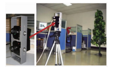 |
Fig. 4 Real-time mosaicking experimental system to manipulate
two cameras for capturing sequential tree images
|
The cameras were coupled with a CCD to capture and store images in a digital memory. The cameras were able to capture tree images at a maximum speed of 30 frames per second(fps). The process of capturing sequential images included defining critical variables,assigning the callback function,turning on the digital cameras,defining camera parameters(focal length,white balance,exposure time and aperture),capturing and processing video images,and turning off the cameras. During the real-time image mosaicking process,the matching area of each pair of images and the final combined image were shown on the computer screen.
The camera parameters were adjusted before the image mosaicking process. This was because the focal length,white balance and aperture affected image clarity,color and image brightness,respectively,as a result to affect the image segmentation. The white balance was adjusted manually through the color finding table with the G component as a benchmark and the ratio of R and B components as input. During the white balance adjustment,all the field-of-view of the lens was made as white,and the automatic white balance adjustment ratio was repeated with the camera Get-White-Balance-Ratio function until clear and precise images were captured.
For a moving object,the camera exposure time affected the clearness of the captured images. The minimum and maximum exposure times of the cameras used in the test were 20 μs and 1 s,respectively. The target image motion(δ,μm)in the camera display was,
| $ \delta = 1000000vt\lambda . $ | (15) |
where,v was the camera travel speed when passing the target tree(m·s-1),t was the exposure time(s),and λ was the optical magnification(or the ratio of target tree image size to the actual tree size). To obtain the satisfied clearness of images,the target image motion(δ)should be shorter than the pixel size of image resolution. For the cameras used in the test,the CCD display height was 3.096 mm and image pixel was 6.45 μm. That is,δ should be shorter than 6.45 μm.
To verify the accuracy of the distance algorithm module,the values for geometry parameters d1 and w were calibrated and determined. Steps included: placing a 2.0 m tall tree at 1.0 and 7.0 m away from the camera st and fixture,taking two pairs of images with the two cameras for the two tree positions,mosaicking each pair of images and using equation(1)to calculate overlapping coefficient K1 and K2,and then using the equations(13) and (14)to calculate the camera setting parameters d1 and w.
An experiment was conducted to verify the accuracy of the algorithm developed for equation(10)to calculate the tree distance D and the overlapping coefficient K. Steps for the experiment were: placing the target trees at 11 different distances from the cameras with a 0.50 m increase for the distances ranging from 1.50 to 6.50 m,moving the tree at 2 m·s-1 speed perpendicularly to the camera optical views,taking sequential pairs of images at different distances,automatically mosaicking pairs of images by pixel overlay of overlapping regions(Zhou et al.,2011)to obtain the overlapping coefficient K at each distance,using equation(10)to calculate the target tree distance with the known values of d1 and w obtained,and then comparing the actual and calculated distances to verify the module accuracy.
3 Results and discussion 3.1 Camera exposure timeAs shown in equation(15),the target image motion(δ)linearly increased as the camera travel speed(v),camera exposure time(t) and optical magnification(λ)increased. Choosing values of v,t,and λ must meet the requirement that δ should be shorter than the CCD display pixel resolution 6.45 μm. For example,when the distance between the camera and target tree was 5 m,the maximum tree height that the camera could display was 12 000 mm. That is,λ=3.096/12 000=0.000 258. If the camera travel speed(v)was 5 m·s-1(18 km·h-1) and δ was equal to 6.45 μm(the image resolution in CCD),the maximum exposure time(t)from equation(15)should be 0.005 s(1/200 s). Similarly,if t was chosen with the SetExposureTime function in the camera as 0.002 s(1/500 s),the maximum travel speed(v)should be 12.5 m·s-1 which was much higher than the travel speed normally used for pesticide sprayers. Therefore,the cameras used in the system were fast enough to capture quality sequential images of trees at high camera travel speeds because their lowest exposure time setting was 20 μs(0.000 02 s).
3.2 Dynamic tree image mosaickingBecause an extensive time was required for mosaicking sequential pairs of images,not all the frames captured at the 30 fps speed could be processed. The processing frequency varied with the image processing time which depended on the template radius of the paired images. During each cycle,the most recent frames in the storage from two cameras were coupled as the start point,and then pairs of partial tree images captured by the two cameras were mosaicked with the tree image mosaicking module.
To maximize mosaicking accuracy,a continuous sorting method was used to match the pairs of images while each pair of images was processed independently to form a new mosaicked image. Every mosaicked image was then compared with the previous mosaicked image to obtain an integrated value for the overlapping coefficient(K). After numerous comparisons of sequential images for the same tree,the average K value was calculated. The experimental results demonstrated that three to five pairs of images could reach a stable K value.
Fig. 5 shows the two images(top left and lower left)captured with two cameras and then were mosaicked into a combined image(middle)in real time. The "green extraction" frame shown at the lower right corner in Fig. 5 was used to make decisions on which segments to be selected for the image mosaicking process. The selected segments were also displayed at the lower right bottom of the interface.
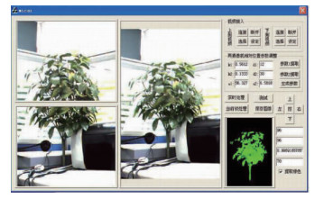 |
Fig. 5 The interface of dynamic tree image
sequence mosaicking system
|
For calibrated result,the overlapping coefficient K obtained from the image mosaicking module was 0.191 7 at D1=1.0 m and was 0.458 3 at D2=7.0 m. Replacing these values into equations(13) and (14)yields the geometry parameters d1=0.618 8 and w=1.989. Then,equation(10)becomes,
| $ D = \frac{{0.6188}}{{1 - 1.989K}}. $ | (16) |
After the values of d1 and w were determined for the image mosaicking hardware platform,the target tree distance could be calculated with equation(16)after automatically mosaicking pairs of images along with the overlapping coefficient(K)value at that distance. Fig. 6 shows the actual target tree distance(D)as the function of K,presented with equation(16). The overlapping coefficient increased non-linearly as the distance increased. This was because the overlapping area increased as the distance increased for the constant camera optical angles. The change in K value became obvious when the cameras were close to the target tree while the K value tended to become a constant as the distance between the cameras and the target tree increased. Therefore,it was critical to calculate the K values accurately for obtaining the accurate distance(D)when the cameras were close to the target tree.
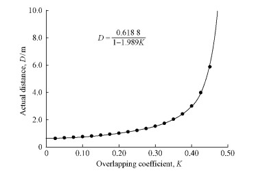 |
Fig. 6 The actual distance between two cameras and the
target tree (D) as the function of overlapping coefficient (K)
obtained from mosaicked pairs of images
|
The K values obtained through the real-time mosaicked pairs of target tree images at 11 different distances were illustrated in table 1. The mosaicked K values agreed well with the calculated K values that employed the actual distances into equation(16)(Fig. 7). The linear coefficient for the calculated and mosaicked K values was 0.966 with r2 of 0.995. Therefore,the image mosaicking module was able to map the pairs of images with a high accuracy.
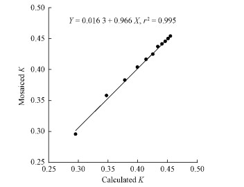 |
Fig. 7Comparison of K values mosaicked through the
real-time tree images and calculated with equation
(16) at 11 different distances
|
Tab. 1 also compares the actual target tree distances and calculated tree distances with equation(16)through the real-time mosaicking pairs of tree images at 11 different distances. Within the range from 1.50 to 6.50 m,the maximum difference between the actual and calculated distances was 0.27 m. The error occurred mainly due to the limitation of image resolution to match the same points on the pairs of images during the mosaicking process. There was no trend showing the error had a relationship with the actual distance(Fig. 8). Within the distance range tested,the maximum error was 7.5%. For shade trees planted on roads,streets,or parks,their height are normally taller than 2.0 m,Compared to these tree heights for target-oriented spray applications,this error should be acceptable.
|
|
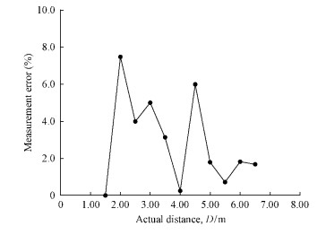 |
Fig. 8Measurement errors of tree distances from
the automatic image mosaicking process
|
Hence,for the pesticide application on high range trees,the sequential pairs of images with the whole tree can be acquired and mosaicked which the integrated tree image can be segmented from the background. Then the high-range target-oriented precision pesticide sprayer will be controlled to spray the pesticide on the target trees according to the mosaicked and segmented tree images.
4 ConclusionsA geometric algorithm,established with 3-D binocular stereo vision concept was developed to calculate the distance between targeted trees and cameras. The targeted tree distance was the function of the mosaicked image overlapping coefficient,camera mounting position,the angle of two cameras optical axes,and optical view angles. The algorithm simplified the function comprising the overlapping coefficient and two measured geometry parameters at two known distances.
Based on the geometric algorithm,an image acquisition and mosaicking system that included an image mosaicking program and hardware platform was developed to capture,process and mosaic sequential images of trees in real time. Validation of the system demonstrated that it was able to accurately measure the tree distance within a 6.5 m range. The difference between the measured and actual distances was less than 0.27 m or 7.5%. Compared to the spacing between trees,this difference was negligible for high-range target-oriented pesticide spray application systems. More precise delivery of pesticides to target trees would be realized by integration of the image mosaicking system with precision spraying systems.
| [1] |
Bielski C, Grazzini J, Soille P. 2007. Automated morphological image composition for mosaicing large image data sets. 2007 IEEE International Geoscience and Remote Sensing Symposium, 4068-4071.( 1) 1)
|
| [2] |
Bignalet-Cazalet F, Baillarin S, Greslou D, et al. 2010. Automatic and generic mosaicing of satellite images. 2010 IEEE International Geoscience and Remote Sensing Symposium, 3158-3161.( 1) 1)
|
| [3] |
Chen Y, Zhu H, Ozkan H E.2012. Development of a variable-rate sprayer with laser scanning sensor to synchronize spray outputs to tree structures. Transactions of the ASABE, 55(3): 773-781( 1) 1)
|
| [4] |
Giles D K, Delwiche M J, Dodd R B. 1988. Electronic measurement of tree canopy volume. Transactions of the ASAE, 31(1): 264-272.( 1) 1)
|
| [5] |
Guestrin C, Cozman F, Godoy Simoes M. 1998. Industrial applications of image mosaicing and stabilization. Second International Conference on Knowledge-Based Intelligent Electronic Systems, 2:174-183.( 1) 1)
|
| [6] |
Hu Tianxiang, Zheng Jiaqiang, Zhou Hongping,et al. 2009.Method on improving segmentation processing speed of dynamic tree image. Scientia Silvae Sinicae, 45(6): 62-67. ( 1) 1)
|
| [7] |
Jeon H Y, Tian L, Zhu H. 2011a. Robust crop and weed segmentation under uncontrolled outdoor illumination. Sensors, 11(6): 6270-6283. ( 2) 2)
|
| [8] |
Jeon H Y, Zhu H, Derksen R C, et al. 2011b. Evaluation of ultrasonic sensors for the variable rate tree liner sprayer development. Computers and Electronics in Agriculture, 75(1): 213-221. ( 1) 1)
|
| [9] |
Jeon H Y, Zhu H. 2012. Development of a variable-rate sprayer for nursery liner applications. Transactions of the ASABE, 55(1): 303-312 ( 1) 1)
|
| [10] |
Joshi M, Jalobeanu A. 2010. MAP estimation for multiresolution fusion in remotely sensed images using an IGMRF prior model. IEEE Transactions on Geoscience and Remote Sensing, 48(3): 1245-1255.( 1) 1)
|
| [11] |
Lee K, Ehsani R. 2008. A laser-scanning system for quantification of tree-geometric characteristics. Applied Engineering in Agriculture, 25(5): 777-788.( 1) 1)
|
| [12] |
Meyer G E, Mehta T, Kocher M F, et al. 1998. Textural imaging and discriminant analysis for distinguishing weeds for spot spraying. Transactions of the ASABE, 41(4): 1189-1197.( 1) 1)
|
| [13] |
Miranda-Luna R, Daul C, Walter C P, et al. 2008. Mosaicing of bladder endoscopic image sequences: distortion calibration and registration algorithm. IEEE Transactions on Biomedical Engineering, 55(2): 541-553.( 1) 1)
|
| [14] |
Nagahdaripour S, Xu X, Khamene A. 1998. Applications of direct 3D motion estimation for underwater machine vision systems. OCEANS’98 Conference Proceedings,1:51-55.( 1) 1)
|
| [15] |
Rosell Polo J R R, Sanz R, Llorens J, et al. 2009. A tractor mounted scanning LIDAR for the non-destructive measurement of vegetative volume and surface area of tree-row plantations: a comparison with conventional destructive measurements. Biosystems Engineering, 102(2): 128-134.( 1) 1)
|
| [16] |
Rzhanov Y, Linnett L M, Forbes R. 2000. Underwater video mosaicing for seabed mapping. Proceedings. 2000 International Conference on Image Processing,1: 224-227.( 1) 1)
|
| [17] |
Sawhney H S, Kumar R. 1999. True multi-image alignment and its application to mosaicing and lens distortion correction. IEEE Transactions on Pattern Analysis and Machine Intelligence, 21(3): 235-243.( 1) 1)
|
| [18] |
Song C, Woodcock C. 2003. Monitoring forest succession with multitemporal landsat images: factors of uncertainty. IEEE Transactions on Geoscience and Remote Sensing, 41(11): 2557-2567. ( 1) 1)
|
| [19] |
Steward B L, Tian L F, Tang L. 2002. Distance-based control system for machine vision-based selective spraying. Transactions of the ASABE 45(5): 1255-1262.( 1) 1)
|
| [20] |
Tian L, Slaughter D C. 1998. Environmentally adaptive segmentation algorithm for outdoor image segmentation. Computers and Electronics in Agriculture, 21(3): 153-168.( 1) 1)
|
| [21] |
Tumbo S D, Salyani M, Whitney J D, et al. 2002. Investigation of laser and ultrasonic ranging sensors for measurements of citrus canopy volume. Applied Engineering in Agriculture, 18(3): 367-372. ( 2) 2)
|
| [22] |
Wang Hangjun,Wang Bihui. 2011. A novel method of softwood recognition. Scientia Silvae Sinicae, 47(10): 141-145. ( 1) 1)
|
| [23] |
Wei J, Salyani M. 2005. Development of a laser scanner for measuring tree canopy characteristics: Phase 2. foliage density measurement. Transactions of the ASABE, 48(4): 1595-1601.( 1) 1)
|
| [24] |
Zaman Q U, Salyani M. 2004. Effects of foliage density and ground speed on ultrasonic measurement of citrus tree volume. Applied Engineering in Agriculture, 20(2): 173-178.( 2) 2)
|
| [25] |
Zheng J, Zhou H, Xu Y. 2006. Precision pesticide application technique. Beijing: Science Press.( 1) 1)
|
| [26] |
Zheng J, Zhou H, Xu Y. 2005. Toward-target precision pesticide application and its system design. Transaction of the CSAE, 21(11): 67-72. ( 1) 1)
|
| [27] |
Zhou B, Zheng J, Zhou H. 2010. Tree image mosaicing system based on featured area matching. Transactions of CSAM, 41(10): 195-198.( 1) 1)
|
| [28] |
Zhou B, Zheng J, Zhou H. 2011. High-tree Image mosaicing and seam processing for precision pesticide application. International Conference on New Technology of Agricultural Engineering,May 27-29, 2011, Zibo, China( 1) 1)
|
 2014, Vol. 50
