2. 佛山市科文自动化设备有限公司, 广东 佛山 528000;
3. 佛山市国星光电股份有限公司 RGB 研发部, 广东 佛山 528000
2. Foshan Kewen Automation Equipment Co., Ltd, Foshan 528000, China;
3. RGB R&D Department, Foshan Nationstar Optoelectronics Co., Ltd., Foshan 528000, China
抓取机构是一种典型的机器人末端执行器,主要用于执行抓取、搬运、放置、释放等操作,在产品分拣装配[1]、农业采摘[2]、微纳操作[3]等领域应用广泛。近年来,随着机器人工作环境由结构化环境向具有操作对象不确定、操作任务复杂等特征的非结构化环境发展,自适应抓取机构引起了国内外研究者广泛关注[4]。其中,良好的自适应能力、快速响应与大负载是自适应抓取机构实现安全可靠的机器人灵巧操作的关键。
在目前的研究中,自适应抓取机构主要分为:刚性欠驱动抓取机构[5-7]、软体抓取机构[8-10]和柔顺抓取机构[11-18]。刚性欠驱动抓取机构的驱动单元数目小于自由度数目,能够利用不受驱动控制的关节自由度被动适应抓取对象的形状[19-20]。但是,刚性欠驱动抓取机构与抓取对象之间存在刚性接触关系,并且刚性欠驱动抓取机构能直接传递驱动单元的刚性冲击,容易损坏易破损和易变形的操作对象。软体抓取机构具有良好的形状自适应性,但其一般采用运动分辨率较低、响应速度较慢的气动或介电弹性体进行驱动[21-22],位姿与载荷的精准、实时调控存在较大困难。柔顺机构利用材料弹性变形实现力或运动的传递或转换,具有一体化成型、免装配等优点,已被广泛应用于微纳操作等对运动精度要求较高的机器人操作领域[23]。传统的柔顺机构大多采用金属等弹性模量较高的材料,以获得高精度的小变形。近年来,国内外学者通过结构设计,采用弹性模量较低的材料[13-18],提出毫米级大行程柔顺抓取机构。这种抓取机构充分结合柔顺机构与柔性材料的顺应性特征,具有较高的形状自适应性,能较好地保护操作对象。但是,柔性材料具有黏弹性特征,导致抓取机构响应速度慢。同时,柔性材料的低弹性模量特性导致机构的抓取平面外刚度偏低,影响负载能力。
为了解决刚性欠驱动抓取机构的刚性接触与刚性冲击问题,并克服软体抓取机构和柔顺抓取机构响应速度慢、负载能力低的缺点,可以采用刚柔结合的设计思想[24]。在国内外研究中,抓取机构的刚柔结合设计方法主要分为2类:驱动柔性化[25-26]、铰链柔性化[27-29]。Chen等[25]基于绳索柔性驱动设计了一种抓取机构,并提出一种自适应逐步抓取过程,将抓取过程的影响因素分为不同的结构参数组合。在这些参数组合中,与执行端位姿相关的动滑轮半径显著影响操作可靠性。所设计的抓取机构及自适应抓取过程的操作稳定性依赖于准确估计执行端位姿、抓取接触点和抓取力,但是,不同操作对象形状在抓取机构的构形空间中会形成不同的几何约束,使得执行端位姿、抓取接触点和抓取力难以估计,导致对不同操作对象难以进行稳定的抓取操作。Dong等[26]采用绳索柔性驱动方式设计了一种欠驱动抓取机构,并以抓取力最大、抓取力偏差最小和包络角度最小作为目标函数,利用遗传算法进行尺寸优化。实验结果显示,该抓取机构具有较高的形状自适应性。Salvietti等[28]设计了一种柔性关节,并利用欧拉-伯努利梁理论建立柔性关节刚度模型,进一步利用该柔性关节代替传统抓取机构的刚性关节,提高了抓取性能和形状适应范围。Hussain等[27, 29]研究一种由刚性杆件和柔顺铰链组成的刚柔结合抓取机构,并基于螺旋理论建立其运动学模型,揭示了柔顺铰链刚度对抓取机构的执行端轨迹、接触刚度和接触力分布的影响,进而可以针对不同的工作要求对柔顺铰链进行优化设计。文[25-29]中,绳索柔性驱动和柔性关节可以吸收部分刚性冲击,但是,执行端与操作对象之间的刚性接触问题仍然未得到解决。
针对现有刚柔结合抓取机构与操作对象之间存在刚性接触的问题,本文结合刚性欠驱动抓取机构与柔顺机构,提出一种新型多模式刚柔结合欠驱动抓取机构,并进行分析与实验测试。首先,对新型多模式刚柔结合欠驱动抓取机构进行结构设计与优选。接着,分别建立驱动单元和抓取单元的静力学模型,并综合运用线性插值与迭代枚举方法,考虑由于接触引起的柔性杆件变形,对抓取力模型进行修正。然后,基于修正后的抓取力模型,对机构尺寸参数进行优化设计,综合提升机构在两点抓取模式和包络抓取模式下的载荷输出性能。最后,对修正后的抓取力模型、优化设计结果进行仿真与实验验证。
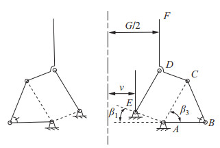
2 刚柔结合欠驱动抓取机构设计(Design of the rigid-flexible underactuated grasping mechanism)图 1为典型的二指刚性欠驱动抓取机构[30],基于刚体替代法,对该机构进行局部柔性化替代,可以形成多模式刚柔结合欠驱动抓取机构。局部柔性化替代分为2种:内刚外柔结构、内柔外刚结构。
|
图 1 典型的二指刚性欠驱动抓取机构示意图 Fig.1 Schematic of the typical two-finger rigid underactuated grasping mechanism |
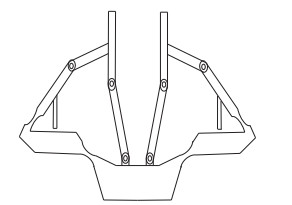
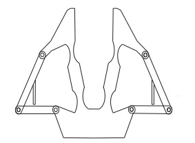
内刚外柔结构是指,与操作对象接触部分(以图 1右半部分为例,即连杆CDF和连杆DE)保持为刚性杆件与刚性铰链,而抓取机构其余部分的连杆和铰链分别由柔性杆件和柔顺铰链替代,如图 2所示。反之,则为内柔外刚结构,如图 3所示。在内刚外柔结构中,带有硬限位装置的铰链
|
图 2 内刚外柔结构 Fig.2 Rigid inside and compliant outside structure |
|
图 3 内柔外刚结构 Fig.3 Compliant inside and rigid outside structure |
在内刚外柔结构中,柔性结构可以缓冲驱动源带来的刚性冲击。但是,由于抓取执行端是由金属等弹性模量较大的材料制成,刚度较高,导致内刚外柔抓取机构与操作对象之间依然存在刚性接触。内柔外刚结构不仅可以缓冲驱动源带来的刚性冲击,还可以通过由低弹性模量材料制成的抓取执行端与操作对象接触,利用材料变形适应操作对象形状,共同保护易损的操作对象。由上述分析可知,采用内柔外刚结构具有更高的安全性。本文后续研究将针对采用内柔外刚结构的多模式刚柔结合欠驱动抓取机构展开。
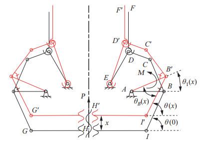
3 驱动单元静力学建模(Static modeling of the driving unit)抓取机构分为驱动单元和抓取单元,其中,驱动单元由直流电机、丝杠螺母副和驱动机构组成。抓取机构左右对称,如图 4所示,图中,黑色、红色部分分别对应抓取运动前后机构的位置。在起始时刻,杆
|
图 4 驱动机构 Fig.4 Driving mechanism |
由几何关系可得;
| $ \begin{equation} \theta_{1} (x)=\arccos \frac{L_{AB} -L_{IB} \cos \theta (0)-L_{{\rm s}} }{L_{AB} -L_{IB} \cos \theta_{B} (x)+L_{{\rm t}}} \end{equation} $ | (1) |
式中,
| $ \begin{align} L_{{\rm s}} &=\frac{L_{IB1} \sin \theta_{B} (x)(x-L_{IB1} \sin \theta (0))}{L_{AB} -L_{IB1} \cos \theta_{B} (x)} \end{align} $ | (2) |
| $ \begin{align} L_{{\rm t}} &=\frac{L_{IB1}^{2} \sin^{2}\theta_{B} (x)}{L_{AB} -L_{IB{\rm 1}} \cos \theta_{B} (x)} \end{align} $ | (3) |
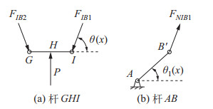
取杆
|
图 5 驱动机构连杆受力分析 Fig.5 Force analysis on the linkages in the driving mechanism |
| $ \begin{align} &F_{IB1} =F_{IB2}, \quad F_{IB1} =F_{NIB1} \end{align} $ | (4) |
| $ \begin{align} &F_{IB1} \sin \theta (x)+F_{IB2} \sin \theta (x)=P \end{align} $ | (5) |
式中,
| $ \begin{equation} P=\frac{2 {\rm{\pi }} \mu T}{s} \end{equation} $ | (6) |
式中,
取杆
| $ \begin{align} M=\;&F_{NIB1} L_{AB} \sin \theta (x)\cos \theta_{1} (x) -\\ &F_{NIB1} L_{AB} \cos \theta (x)\sin \theta_{1} (x) \end{align} $ | (7) |
联立式(4)~(7) 解得
| $ \begin{equation} M=\frac{{\rm{\pi }} \mu TL_{AB} \sin (\theta (x)-\theta_{1} (x))}{s\sin \theta (x)} \end{equation} $ | (8) |
本文所提出的刚柔结合欠驱动抓取机构具有两点抓取和包络抓取2种操作模式[30]。在两点抓取模式下,操作对象与抓取机构之间产生平面接触,执行端DF保持竖直状态。包络抓取模式可用于操作具有复杂轮廓的物体,此时,杆DE、CDF共同参与抓取操作。
4.1 两点抓取模式抓取力建模由于在两点抓取模式下,执行端DF需保持竖直状态,可以进一步获得2个几何约束:(1) 四边形ACDE在抓取过程中保持为平行四边形;(2)
由图 6可得

|
图 6 两点抓取模式下抓取单元伪刚体模型受力分析 Fig.6 Force analysis on the pseudo-rigid-body model of the grasping unit in the two-point grasping mode |
| $ \begin{equation} \theta_{4} =\arccos \frac{0.5L-v}{L_{DE}}, \quad \beta_{3} =\theta_{4} -\theta_{1} \end{equation} $ | (9) |
式中,
图 7(a)为两点抓取模式的初始位置(杆

|
图 7 两点抓取模式初始位置与抓取运动后位置的示意图 Fig.7 Schematic illustration of the initial position and the position after grasping motion in the two-point grasping mode |
| $ \begin{align} \alpha_{D0} &=180^{\circ} -\beta_{3} -\beta_{1} \end{align} $ | (10) |
| $ \begin{align} \alpha_{D} &=180^{\circ} -\beta_{3} -\beta_{1} -\theta_{1} \end{align} $ | (11) |
| $ \begin{align} \Delta \alpha_{D} &=-\Delta \alpha_{E} =\alpha_{D} -\alpha _{D0} =-\theta_{1} \end{align} $ | (12) |
圆弧型柔顺铰链(如图 8所示)的转动精度高、制造加工简便,已经被广泛应用于各类柔顺机构[14, 31-32]。因此,在本文所提出的刚柔结合欠驱动抓取机构中,所有柔顺铰链均为圆弧型柔顺铰链。在伪刚体模型中,扭簧刚度取为圆弧型柔顺铰链的转动刚度,其计算公式为[33]

|
图 8 圆弧型柔顺铰链 Fig.8 Circular flexure hinge |
| $ \begin{equation} K=\frac{12}{Ebr^{2}}(X+Y+Z) \end{equation} $ | (13) |
式中,
| $ \begin{align} \theta_{{\rm m}} &=\arccos \frac{r-0.5(w-t)}{r} \end{align} $ | (14) |
| $ \begin{align} X&=\frac{8s^{4}(2s+1)\tan (0.5\theta_{{\rm m}}) }{(4s+1)^{2}[1+(4s+1)\tan ^{2}(0.5\theta_{{\rm m}})]} \end{align} $ | (15) |
| $ \begin{align} Y&=\frac{4s^{3}(6s^{2}+3s+1)\tan (0.5\theta_{{\rm m}} )}{(4s+1)^{2}[1+(4s+1)\tan^{2}(0.5\theta_{{\rm m}})]} \end{align} $ | (16) |
| $ \begin{align} Z&=\frac{12s^{4}(2s+1)\arctan [\sqrt{4s+1}\tan (0.5\theta_{{\rm m}} )]}{(4s+1)^{\frac{5}{2}}} \end{align} $ | (17) |
式中,
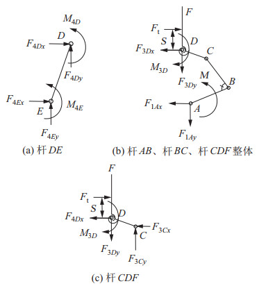
取杆DE作分离体,进行受力分析,如图 9(a)所示。以
|
图 9 两点抓取模式下各杆件受力分析 Fig.9 Force analysis on each linkage in the two-point grasping mode |
| $ \begin{align} M_{4E} +M_{4D} -F_{4Dx} L_{DE} \sin \theta_{4}+ F_{4Dy} L_{DE} \cos \theta_{4} =0 \end{align} $ | (18) |
式中,
| $ \begin{equation} M_{4D} =M_{4E} =K\Delta \alpha_{D} \end{equation} $ | (19) |
取杆
| $ \begin{equation} -F_{{\rm t}} S_{1} -F_{3Dy} S_{2} -F_{3Dx} S_{3} +M-M_{3D}=0 \end{equation} $ | (20) |
式中,
| $ \begin{align} F_{3Dy} &=-F_{4Dy} \end{align} $ | (21) |
| $ \begin{align} S_{1} &=S+L_{CD} \sin \beta_{1} +L_{DE} \sin \theta_{4} \end{align} $ | (22) |
| $ \begin{align} S_{2} &=L_{CD} \cos \beta_{1} -L_{DE} \cos \theta_{4} \end{align} $ | (23) |
| $ \begin{align} S_{3} &=L_{DE} \sin \theta_{4} +L_{CD} \sin \beta_{1} \end{align} $ | (24) |
取杆CDF为分离体作受力分析,如图 9(c)所示。以
| $ \begin{align} -F_{{\rm t}} S_{4} -F_{3Dy} L_{CD} \cos \beta_{1} -F_{3Dx}L_{CD} \sin \beta_{1} +M_{3D} =0 \end{align} $ | (25) |
式中,
| $ \begin{equation} S_{4} =S+L_{CD} \sin \beta_{1} \end{equation} $ | (26) |
联立式(18)~(26) 解得
| $ \begin{equation} F_{{\rm t}} =\frac{M-2M_{4E}} {L_{DE} \sin \theta_{4}} \end{equation} $ | (27) |
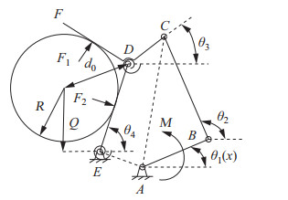
在包络抓取模式下,四边形
|
图 10 包络抓取模式下抓取单元伪刚体模型受力分析 Fig.10 Force analysis on the pseudo-rigid-body model for the grasping unit in the enveloped grasping mode |
| $ \begin{align} & -L_{CD} \cos \beta_{1} +L_{DE} \cos \theta_{4} \\ =& L_{AB} \cos \theta_{1} +L_{BC} \cos \theta_{2} -L_{CD} \cos \theta_{3} \end{align} $ | (28) |
| $ \begin{align} & L_{CD} \sin \beta_{1} +L_{DE} \sin \theta_{4} \\ =&L_{AB} \sin \theta_{1} +L_{BC} \sin \theta_{2} -L_{CD} \sin \theta_{3} \end{align} $ | (29) |
根据几何关系,
| $ \begin{align} \cos \theta_{4} &=\frac{R}{v\tan \theta_{4} +Q} \end{align} $ | (30) |
| $ \begin{align} \theta_{3} &=180^{\circ} -\beta_{2} -\left(2\arcsin \frac{R}{d_{0}} -\theta_{4}\right) \end{align} $ | (31) |
式中,
| $ \begin{equation} d_{0} =\sqrt{m^{2}+n^{2}-2mn\cos (90^{\circ} -\theta_{4}) } \end{equation} $ | (32) |
式中,
| $ \begin{equation} m=L_{DE} +\frac{v}{\cos \theta_{4}}, \quad n=Q+v\tan \theta_{4} \end{equation} $ | (33) |
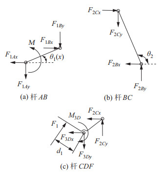
取杆
|
图 11 包络抓取模式下各杆件受力分析 Fig.11 Force analysis on each linkage in the enveloped grasping mode |
以
| $ \begin{equation} M-F_{1Bx} L_{AB} \sin \theta_{1} +F_{1By} L_{AB} \cos \theta_{1} =0 \end{equation} $ | (34) |
取杆BC为分离体作受力分析,如图 11(b)所示。以
| $ \begin{equation} F_{2Bx} L_{BC} \sin \theta_{2} -F_{2By} L_{BC} \cos \theta_{2} =0 \end{equation} $ | (35) |
取杆CDF为分离体作受力分析,如图 11(c)所示。以
| $ \begin{align} &F_{3Cy} L_{CD} \cos \theta_{3} -F_{3Cx} L_{CD} \sin \theta_{3}+ \\ &\quad M_{3D} -F_{1} \sqrt{d_{0}^{2} -R^{2}}=0 \end{align} $ | (36) |
联立式(34)~(36) 解得
| $ \begin{equation} F_{1} =\frac{ML_{CD} \sin (\theta_{2} -\theta_{3}) }{L_{AB} \sqrt{d_{0}^{2} -R^{2}}\sin (\theta_{2} -\theta_{1}) }-\frac{M_{3D} }{\sqrt{d_{0}^{2} -R^{2}}} \end{equation} $ | (37) |
式中,
| $ \begin{align} M_{3D} &=K(\theta_{4} -\beta_{1} -\beta_{3} -\theta_{3}) \end{align} $ | (38) |
| $ \begin{align} \beta_{3} &=\arccos \frac{L_{AB}^{2} +L_{DE}^{2} -L_{BC}^{2}} {2L_{AB} L_{DE}} \end{align} $ | (39) |
由
| $ \begin{equation} F_{2} =-\frac{F_{1} \cos (\theta_{3} +\beta_{2}) }{\cos \theta_{4}} \end{equation} $ | (40) |
在包络抓取模式下,
对于包络抓取模式下受力平衡时抓取对象的位置,可以用操作对象的中心到铰链
| $ \begin{align} &F_{1} \sin (\beta_{2} +\theta_{3}) -F_{3Cx} -F_{3Dx} =0 \end{align} $ | (41) |
| $ \begin{align} &-F_{1} \cos (\beta_{2} +\theta_{3}) +F_{3Cy} -F_{3Dy} =0 \end{align} $ | (42) |
由作用力与反作用力之间的关系,
| $ \begin{equation} F_{4Dx} =-F_{3Dx}, \quad F_{4Dy} =-F_{3Dy} \end{equation} $ | (43) |
由杆DE的力矩平衡条件得
| $ \begin{align} \sum {M_{E}}&=-M_{4E} +M_{4D}-F_{4Dx} L_{DE} \sin \theta_{4} +\\ &\quad\; F_{4Dy} L_{DE} \cos \theta _{4} -\\ &\quad\; F_{2} R/[180-\arctan (Q/v)-\theta_{4}] \end{align} $ | (44) |
联立式(41)~(44),可以获得
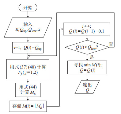
|
图 12 包络抓取模式下操作对象平衡位置的枚举搜索流程 Fig.12 Enumerating search process of the equilibrium position for the operated object in the enveloped grasping mode |
以后文第6节组1为例,以一定步长枚举
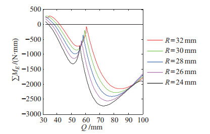
|
图 13 一定步长下枚举Q并记录对应的∑ME值 Fig.13 Enumerating Q at certain step length, and recoding the corresponding ∑ME |
由于本文提出的二指多模式刚柔结合欠驱动抓取机构采用内柔外刚结构,在抓取执行端与操作对象接触时,执行端会发生弹性变形,影响载荷平衡状态。然而,在上述抓取单元静力学建模过程中,载荷平衡方程的建立并未考虑执行端的弹性变形,增加了静力学建模误差。
由于存在接触变形,达到一定抓取力所需的驱动杆
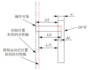
|
图 14 抓取执行端与操作对象接触时抓取执行端的弹性变形(两点抓取模式) Fig.14 Elastic deformation of the grasping port when contacting with the operated object (two-point grasping mode) |
| $ \begin{equation} L_{{\rm r}} =2[v+L_{DE} \cdot \cos (\beta_{3} +\theta_{1} (x_{{\rm r}} ))] \end{equation} $ | (45) |
由于存在接触变形,达到一定抓取力所需的驱动杆
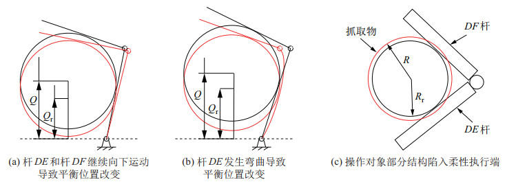
|
图 15 抓取执行端与操作对象接触时操作对象平衡位置的变化与抓取执行端的弹性变形(包络抓取模式) Fig.15 Change of the equilibrium position for the operated object and the elastic deformation of the grasping port when the grasping port contacts with the operated object (enveloped grasping mode) |
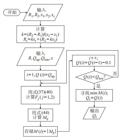
为了获得
|
图 16 采用线性插值法修正枚举搜索 Fig.16 Correcting the enumerating search by linear interpolation |
|
|
表 1 仿真算例中的x1、x2、xr、Q、Qr数值 Tab. 1 Values of x1, x2, xr, Q, Qr in the simulation example |
将利用图 16得到的
本节通过构造尺寸参数的约束优化模型,实现多模式抓取力最大化,以综合提升机构在两点抓取模式和包络抓取模式下的载荷输出性能。
在抓取机构尺寸参数中,
| $ \begin{equation} L_{BC} =\arccos\frac{0.5G-v}{L_{DE}} +\beta_{1} \end{equation} $ | (46) |
在抓取单元静力学建模过程中,式(13) 是建立在欧拉-伯努利梁理论基础上,因此,柔顺铰链的长宽比不能小于5[34]。此外,由于所提出的抓取机构是集中柔度柔顺机构,因此连杆的抗弯刚度应远大于柔顺铰链的抗弯刚度。
综上分析,在两点抓取模式下,机构的优化模型可以表述为
| $ \begin{align} &\max\; F_{{\rm t}}\\ &{\rm s.t}.\; l=2\sqrt{r^{2}-\left(r+\frac{1}{2}t-\frac{1}{2}w\right)^{2}}\geqslant 5t \\ &\quad\; \; EI_{1} \geqslant 10EI_{\rm h} \end{align} $ | (47) |
由式(37)(40) 及4.3节分析可知,等效综合包络抓取力与
| $ \begin{align} &\max\; F_{\rm e}\\ &{\rm s.t}.\; l=2\sqrt{r^{2}-\left(r+\frac{1}{2} t-\frac{1}{2}w\right)^{2}} \geqslant 5t \\ &\quad \; \; EI_{1} \geqslant 10EI_{\rm h} \\ &\quad \; \; \beta_{3} =\arccos \frac{L_{AB}^{2}+L_{BC}^{2}-L_{DE} ^{2}}{2L_{AB} L_{BC}} <90^{\circ} \end{align} $ | (48) |
在优化模型式(47)(48) 中,设计变量取值范围如表 2所示。
|
|
表 2 设计变量初值与取值范围 Tab. 2 Initial value and range of the design variables |
运用Matlab软件的fmincon函数,可以求解约束优化模型。在目标函数中,等效综合包络抓取力

|
图 17 包络抓取模式下优化算法流程图 Fig.17 Flow chart of the optimization algorithm in the enveloped grasping mode |
设计变量初始组如表 2所示,在2种抓取模式下,机构尺寸参数的优化结果如表 3所示。一方面,在2种抓取模式下,
|
|
表 3 优化算法结果 Tab. 3 Results of the optimization algorithm |
将上述驱动单元静力学建模、抓取单元静力学建模与模型修正相结合,可以得到修正后完整的多模式抓取力模型。为了验证模型的有效性,本节采用5组算例(如表 4所示),在RecurDyn软件中对刚柔结合欠驱动抓取机构及其伪刚体模型进行仿真分析。进一步地,将以组1为初始组,通过RecurDyn仿真,验证尺寸优化模型的有效性。
|
|
表 4 抓取机构参数 |
在各组算例中,预设参数为:
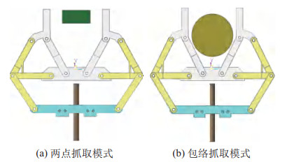
|
图 18 在RecurDyn软件中建立抓取机构伪刚体模型 Fig.18 Pseudo-rigid body model of the grasping mechanism established in RecurDyn software |
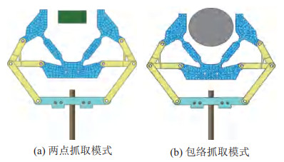
|
图 19 在RecurDyn软件中建立刚柔结合抓取机构模型 Fig.19 Rigid-flexible grasping mechanism model established in RecurDyn software |
在RecurDyn软件中建立抓取机构伪刚体模型时,抓取单元柔性结构的杆件可等效为刚体,柔顺铰链可等效为刚性转动副和一个刚度为
此外,在RecurDyn软件中分别建立优化组及其对应的内刚外柔抓取机构(对照组)模型。在驱动杆上加载具有相同时域特性的冲击推力(当
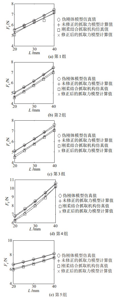
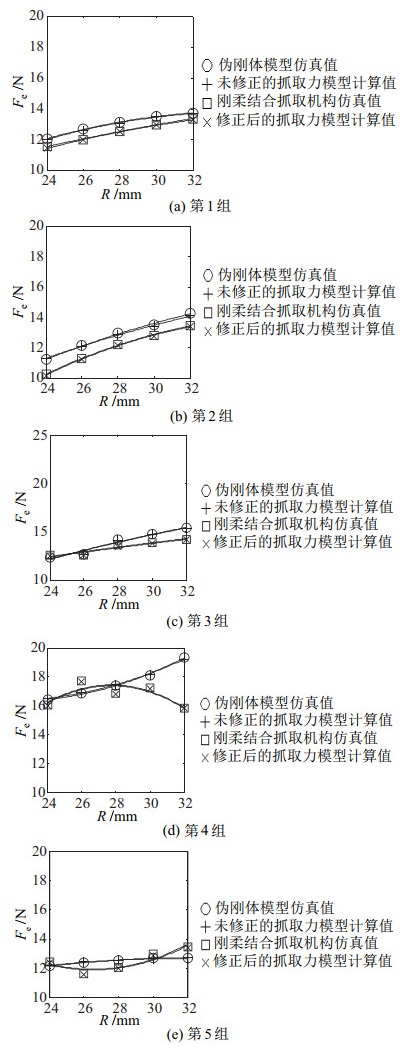
5组算例在2种抓取模式下的仿真结果如图 20和图 21所示。在两点抓取模式下,未修正的抓取力模型计算值与伪刚体模型仿真值的最大相对误差为2.73%;在包络抓取模式下,该最大相对误差为1.92%。上述结果验证了基于伪刚体模型法的抓取力建模在推导上的正确性。进一步地,在两点抓取模式下,修正后的抓取力模型计算值与刚柔结合抓取机构模型仿真值的最大相对误差为7.62%;在包络抓取模式下,该最大相对误差为1.95%。上述结论验证了修正后完整的抓取力模型的有效性。
|
图 20 两点抓取模式下仿真结果对比 Fig.20 Comparison of the simulation results in the two-point grasping mode |
|
图 21 包络抓取模式下仿真结果对比 Fig.21 Comparison of the simulation results in the enveloped grasping mode |
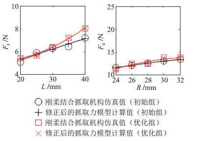
进一步地,对初始组与优化组分别进行仿真,如图 22所示。在两点抓取模式下,对于尺寸较小的抓取对象(
|
图 22 优化结果对比 Fig.22 Comparison of the optimization results |
通过上述比较可知,相比于初始组,优化组的两点抓取力和包络抓取力均得到提升,验证了优化算法的有效性。同时,对于优化组,修正后的抓取力模型计算值与刚柔结合抓取机构仿真值之间具有良好的一致性,进一步验证了修正后的抓取力模型的有效性。
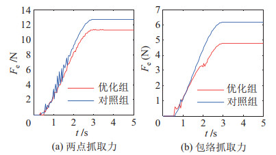
最后,图 23展示优化组与对照组抓取力仿真时域图。对于两点抓取仿真,优化组与对照组抓取力均无明显振荡;对于包络抓取仿真,对照组的抓取力在1 s~2 s时会产生较大的振荡,而优化组抓取力在整个加载过程中均无明显振荡。上述结果验证了,相比内刚外柔结构,采用内柔外刚结构的抓取机构在包络抓取过程中缓冲驱动源带来冲击的能力更强。
|
图 23 加载冲击推力时优化组与对照组抓取力仿真时域图 Fig.23 Simulation time-domain diagram of the grasping forces for the optimal group and the comparative group when loading the shock pushing force |
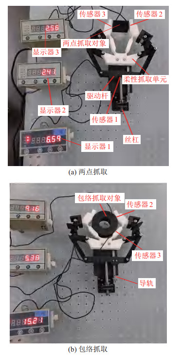
按照优化组的尺寸,制作出对应的刚柔结合抓取机构样机,并对抓取力建模有效性进行实验验证,如图 24~图 27所示。
|
图 24 实验样机示意图 Fig.24 Schematic illustration of the experimental prototype |

|
图 25 传感器1布置示意图 Fig.25 Schematic illustration of placing sensor 1 |

|
图 26 两点抓取模式下力传感器的布置示意图 Fig.26 Schematic illustration of placing the force sensors in the two-point grasping mode |
|
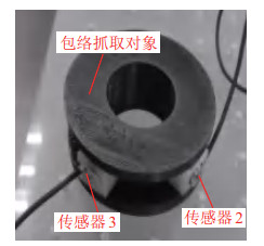
图 27 包络抓取模式下力传感器的布置示意图 Fig.27 Schematic illustration of placing the force sensors in the enveloped grasping mode |
抓取机构刚性部分的材料选用PLA热塑性塑料,柔性部分的材料选用邵氏硬度A为80 HA的软胶材料。由于PLA塑料的弹性模量远大于软胶,所以由PLA塑料通过3D打印制成的杆件可以视为刚性部分。使用3个高精度力传感器(蚌埠大洋传感系统工程有限公司DYHW-108型)对驱动力和抓取力进行测量。其中,驱动力指丝杠前进对驱动杆产生的推力,由传感器1测量,抓取力由传感器2、3测量。
测量时,首先使杆
抓取力实验时域图(图 28和图 29)显示,当驱动杆推力稳定在一定值后,对于不同尺寸的抓取对象,系统均能稳定地输出一定的抓取力,验证了抓取机构输出力的稳定性。
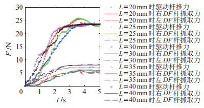
|
图 28 优化组两点抓取力实验时域图 Fig.28 Experimental time-domain diagram of the two-point grasping force for the optimal group |
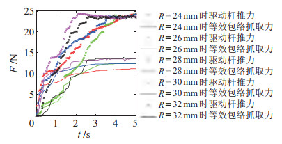
|
图 29 优化组包络抓取力实验时域图 Fig.29 Experimental time-domain diagram of the enveloped grasping force for the optimal group |
实验结果(图 30)显示,修正后完整的抓取力模型计算值、刚柔结合抓取机构仿真值与实验值具有较好的一致性。在两点抓取模式下,修正后完整的抓取力模型计算值与实验值的最大相对误差为1.87%;在包络抓取模式下,修正后完整的抓取力模型计算值与实验值的最大相对误差为1.05%。上述结论从实验层面验证了修正后完整的多模式抓取力模型的有效性。
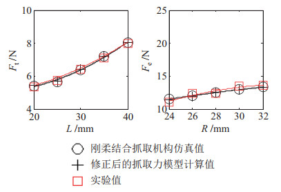
|
图 30 理论值、仿真值、实验结果对比 Fig.30 Comparison among the theoretical values, simulation values, and experimental results |
本文结合刚性欠驱动抓取机构与柔顺机构,提出一种新型多模式刚柔结合欠驱动抓取机构,并对所提出的机构进行分析与实验研究。基于刚体替代法,设计了二指多模式欠驱动抓取机构的刚柔结合方案。运用正运动学分析与载荷平衡方程,对驱动单元进行静力学建模。结合伪刚体模型法、载荷平衡方程与抓取对象平衡位置枚举搜索,建立两点抓取与包络抓取模式下抓取力与驱动力矩的关系式。将驱动单元静力学建模与抓取单元静力学建模相结合,可以得到完整的多模式抓取力模型。进一步地,考虑由于接触引起的柔性杆件变形,结合线性插值,对抓取力模型进行修正。基于修正后的抓取力模型,对机构尺寸参数进行优化设计,综合提升机构在两点抓取模式和包络抓取模式下的载荷输出性能。主要结论如下:
(1) 采用内柔外刚结构,设计二指多模式欠驱动抓取机构的刚柔结合方案,避免了抓取机构与操作对象之间的刚性接触。同时,相比内刚外柔结构,采用内柔外刚结构的抓取机构在包络抓取过程中缓冲驱动源带来冲击的能力更强。
(2) RecurDyn仿真结果显示,在两点抓取模式和包络抓取模式下,修正后的抓取力模型与仿真值的最大相对误差为7.62%;并且所提出的优化算法有效提升了机构的两点抓取力与综合包络抓取力,相比初始组,最大提升率分别为12.18%、2.34%,抓取力建模与优化设计算法具备有效性。
(3) 实验结果显示,抓取机构输出力具有稳定性,修正后的抓取力模型与实验值的最大相对误差为1.87%,进一步验证了抓取力建模的有效性。
| [1] |
Mahler J, Matl M, Satish V, et al. Learning ambidextrous robot grasping policies[J]. Science Robotics, 2019, 4(26). DOI:10.1126/scirobotics.aau4984 |
| [2] |
张千, 高国琴. 并联机器人串类水果抓取模型及抓取位姿计算[J]. 农业工程学报, 2019, 35(23): 37-47. Zhang Q, Gao G Q. Grasping model and pose calculation of parallel robot for fruit cluster[J]. Transactions of the Chinese Society of Agricultural Engineering, 2019, 35(23): 37-47. DOI:10.11975/j.issn.1002-6819.2019.23.005 |
| [3] |
Chen W L, Zhang X M, Fatikow S. Design, modeling and test of a novel compliant orthogonal displacement amplification mechanism for the compact micro-grasping system[J]. Microsystem Technologies, 2017, 23(7): 2485-2498. DOI:10.1007/s00542-016-2989-x |
| [4] |
Hodson R. How robots are grasping the art of gripping[J]. Nature, 2018, 557(7704): S23-S25. DOI:10.1038/d41586-018-05093-1 |
| [5] |
梁达尧, 张文增. 平夹自适应欠驱动手的参数优化与稳定性分析[J]. 机器人, 2017, 39(3): 282-291. Liang D R, Zhang W Z. Parameters optimization and stability analysis for a parallel and self-adaptive underactuated hand[J]. Robot, 2017, 39(3): 282-291. |
| [6] |
Kobayashi A, Yamaguchi K, Kinugawa J, et al. Analysis of precision grip force for uGRIPP (underactuated gripper for power and precision grasp)[C]//IEEE/RSJ International Conference on Intelligent Robots and Systems. Piscataway, USA: IEEE, 2017: 1937-1942.
|
| [7] |
张祥, 苏衍宇, 王伟东, 等. 一种平面混合驱动夹持器的结构优化设计[J]. 机器人, 2016, 38(3): 343-351. Zhang X, Su Y Y, Wang W D, et al. A structural optimization design method of planar hybrid gripper[J]. Robot, 2016, 38(3): 343-351. |
| [8] |
Zhang H, Kumar A S, Fuh J Y H, et al. Design and development of a topology-optimized three-dimensional printed soft gripper[J]. Soft Robotics, 2018, 5(5): 650-661. DOI:10.1089/soro.2017.0058 |
| [9] |
Brown E, Rodenberg N, Amend J, et al. Universal robotic gripper based on the jamming of granular material[J]. Proceedings of the National Academy of Sciences, 2010, 107(44): 18809-18814. DOI:10.1073/pnas.1003250107 |
| [10] |
Chen Y, Guo S F, Li C F, et al. Size recognition and adaptive grasping using an integration of actuating and sensing soft pneumatic gripper[J]. Robotics and Autonomous Systems, 2018, 104: 14-24. DOI:10.1016/j.robot.2018.02.020 |
| [11] |
Krishnan S, Saggere L. Design and development of a novel micro-clasp gripper for micromanipulation of complex-shaped objects[J]. Sensors and Actuators A: Physical, 2012, 176: 110-123. DOI:10.1016/j.sna.2011.09.030 |
| [12] |
Boudreault E, Gosselin C M. Design of sub-centimetre underactuated compliant grippers[C]//ASME International Design Engineering Technical Conferences and Computers and Information in Engineering Conference. New York, USA: ASME, 2006: 119-127.
|
| [13] |
Foody J, Maxwell K, Hao G, et al. Development of a low-cost underactuated and self-adaptive robotic hand[C]//ASME Design Engineering Technical Conferences and Computers and Information in Engineering Conference. New York, USA: ASME, 2014. DOI: 10.1115/DETC2014-35075.
|
| [14] |
Huang M X, Lu Q H, Chen W L, et al. Design, analysis, and testing of a novel compliant underactuated gripper[J]. Review of Scientific Instruments, 2019, 90(4). DOI:10.1063/1.5088439 |
| [15] |
Petković D, Jovic S, Anicic O, et al. Analyzing of flexible gripper by computational intelligence approach[J]. Mechatronics, 2016, 40: 1-16. DOI:10.1016/j.mechatronics.2016.09.001 |
| [16] |
Petković D, Pavlović N D, Shamshirband S, et al. Development of a new type of passively adaptive compliant gripper[J]. Industrial Robot, 2013, 40(6): 610-623. DOI:10.1108/IR-12-2012-452 |
| [17] |
Liu C-H, Chiu C-H. Optimal design of a soft robotic gripper with high mechanical advantage for grasping irregular objects[C]//IEEE International Conference on Robotics and Automation. Piscataway, USA: IEEE, 2017: 2846-2851.
|
| [18] |
Liu C H, Chen T L, Chiu C H, et al. Optimal design of a soft robotic gripper for grasping unknown objects[J]. Soft Robotics, 2018, 5(4): 452-465. DOI:10.1089/soro.2017.0121 |
| [19] |
Cui J, Yan S B, Hu J, et al. A metric to design spring stiffness of underactuated fingers for stable grasp[J]. Robotics and Autonomous Systems, 2018, 102: 1-12. DOI:10.1016/j.robot.2018.01.001 |
| [20] |
Saliba M A, de Silva C W. Quasi-dynamic analysis, design optimization, and evaluation of a two-finger underactuated hand[J]. Mechatronics, 2016, 33: 93-107. DOI:10.1016/j.mechatronics.2015.09.007 |
| [21] |
Jiang P, Yang Y D, Chen M Z Q, et al. A variable stiffness gripper based on differential drive particle jamming[J]. Bioinspiration & Biomimetics, 2019, 14(3). DOI:10.1088/1748-3190/ab04d1 |
| [22] |
Wang N F, Cui C Y, Guo H, et al. Advances in dielectric elastomer actuation technology[J]. Science China: Technological Sciences, 2018, 61(10): 1512-1527. DOI:10.1007/s11431-017-9140-0 |
| [23] |
于靖军, 郝广波, 陈贵敏, 等. 柔性机构及其应用研究进展[J]. 机械工程学报, 2015, 51(13): 53-68. Yu J J, Hao G B, Chen G M, et al. State-of-art of compliant mechanisms and their applications[J]. Journal of Mechanical Engineering, 2015, 51(13): 53-68. |
| [24] |
闫继宏, 石培沛, 张新彬, 等. 软体机械臂仿生机理、驱动及建模控制研究发展综述[J]. 机械工程学报, 2018, 54(15): 1-14. Yan J H, Shi P P, Zhang X B, et al. Review of biomimetic mechanism, actuation, modeling and control in soft manipulators[J]. Journal of Mechanical Engineering, 2018, 54(15): 1-14. |
| [25] |
Chen W R, Xiong C H. On adaptive grasp with underactuated anthropomorphic hands[J]. Journal of Bionic Engineering, 2016, 13(1): 59-72. DOI:10.1016/S1672-6529(14)60160-8 |
| [26] |
Dong H, Asadi E, Qiu C, et al. Geometric design optimization of an under-actuated tendon-driven robotic gripper[J]. Robotics and Computer-Integrated Manufacturing, 2018, 50: 80-89. DOI:10.1016/j.rcim.2017.09.012 |
| [27] |
Hussain I, Salvietti G, Malvezzi M, et al. On the role of stiffness design for fingertip trajectories of underactuated modular soft hands[C]//IEEE International Conference on Robotics and Automation. Piscataway, USA: IEEE, 2017: 3096-3101.
|
| [28] |
Salvietti G, Hussain I, Malvezzi M, et al. Design of the passive joints of underactuated modular soft hands for fingertip trajectory tracking[J]. IEEE Robotics and Automation Letters, 2017, 2(4): 2008-2015. DOI:10.1109/LRA.2017.2718099 |
| [29] |
Hussain I, Renda F, Iqbal Z, et al. Modeling and prototyping of an underactuated gripper exploiting joint compliance and modularity[J]. IEEE Robotics and Automation Letters, 2018, 3(4): 2854-2861. |
| [30] |
卢清华, 黄铭贤, 陈为林. 平面阻尼型欠驱动夹持器的多模式参数优化设计[J]. 工程设计学报, 2018, 25(6): 690-696. Lu Q H, Huang M X, Chen W L. Multi-mode parametric optimization design of planar damped underactuated gripper[J]. Chinese Journal of Engineering Design, 2018, 25(6): 690-696. DOI:10.3785/j.issn.1006-754X.2018.06.010 |
| [31] |
Wang F J, Liang C M, Tian Y L, et al. Design of a piezoelectricactuated microgripper with a three-stage flexure-based amplification[J]. IEEE/ASME Transactions on Mechatronics, 2015, 20(5): 2205-2213. |
| [32] |
Wang R, Wu H, Wang H, et al. Design and stiffness modeling of a four-degree-of-freedom nanopositioning stage based on sixbranched-chain compliant parallel mechanisms[J]. Review of Scientific Instruments, 2020, 91(6). DOI:10.1063/5.0008905 |
| [33] |
吴鹰飞, 周兆英. 柔性铰链转动刚度计算公式的推导[J]. 仪器仪表学报, 2004, 25(1): 125-128, 137. Wu Y F, Zhou Z Y. Deduction of design equation of flexure hinge[J]. Chinese Journal of Scientific Instrument, 2004, 25(1): 125-128, 137. |
| [34] |
Lobontiu N. Compliant mechanisms: Design of flexure hinges[M]. Boca Raton, USA: CRC Press, 2020.
|
 2022, Vol. 44


