
Application of Feature, Event, and Process Methods to Leakage Scenario Development for Offshore CO2 Geological Storage
https://doi.org/10.1007/s11804-024-00441-2
-
Abstract
Offshore carbon dioxide (CO2) geological storage (OCGS) represents a significant strategy for addressing climate change by curtailing greenhouse gas emissions. Nonetheless, the risk of CO2 leakage poses a substantial concern associated with this technology. This study introduces an innovative approach for establishing OCGS leakage scenarios, involving four pivotal stages, namely, interactive matrix establishment, risk matrix evaluation, cause–effect analysis, and scenario development, which has been implemented in the Pearl River Estuary Basin in China. The initial phase encompassed the establishment of an interaction matrix for OCGS systems based on features, events, and processes. Subsequent risk matrix evaluation and cause-effect analysis identified key system components, specifically CO2 injection and faults/features. Building upon this analysis, two leakage risk scenarios were successfully developed, accompanied by the corresponding mitigation measures. In addition, this study introduces the application of scenario development to risk assessment, including scenario numerical simulation and quantitative assessment. Overall, this research positively contributes to the sustainable development and safe operation of OCGS projects and holds potential for further refinement and broader application to diverse geographical environments and project requirements. This comprehensive study provides valuable insights into the establishment of OCGS leakage scenarios and demonstrates their practical application to risk assessment, laying the foundation for promoting the sustainable development and safe operation of ocean CO2 geological storage projects while proposing possibilities for future improvements and broader applications to different contexts.Article Highlights● Establishment of an interactive matrix for offshore CO2 geological storage systems based on Features, events, and processes.● Evaluation of risk matrix and causal analysis to identify key system components, such as CO2 injection and faults/features.● Development of two leakage risk scenarios along with corresponding mitigation measures.● Application of scenario development in risk assessment, including numerical simulation and quantitative assessment, contributing to the sustainable development and safe operation of offshore CO2 geological storage projects. -
1 Introduction
Offshore CO2 geological storage (OCGS) refers to the technology of injecting CO2 in to the reservoir beneath the seabed. This approach was first proposed in 1996 and has since undergone significant development and active promotion (Dewar et al., 2021) and has received increasing attention as an effective means to reduce CO2 emissions and combat climate change (IPCC, 2007; Jiang, 2011; Kanberoğlu et al., 2023; Lackner, 2003; Li and Liu, 2016). In recent years, several offshore storage projects have been implemented internationally, one of which is the Sleipner CCS project (Kapetaki et al., 2017) developed by Statoil (now Equinor) in the Norwegian North Sea in 1996, which is the first commercial CO2 marine storage project in the world and has served as a pioneering initiative in demonstrating the technical and environmental viability of OCGS. Other significant projects include the Gorgon CCS project developed by Chevron, ExxonMobil, and Royal in Australia (Flett et al., 2009), which is the world's largest single saline aquifer storage project; the Tomakomai CCS demonstration project in the Tomakomai region of Hokkaido launched by the Japanese government in 2016; and the British Peterhead project jointly developed by the Scottish and Southern Energy Company and Shell (Bourne et al., 2014). However, because of the lack of experience, immature technology, and high cost, more efforts are needed for large-scale commercial applications.
Normally, CO2 storage sites are located in areas with relatively stable geological structures, that is, without earthquakes, volcanoes, or active fault development zones, to avoid adverse geological factors affecting the effectiveness and safety of storage. However, because of the wide range of storage sites, completely avoiding the existence of unfavorable geological structures on a large scale is difficult. After CO2 is injected into the reservoir, it increases the pressure in the reservoir and migrates to the reservoir. If the potential leakage path (such as wellbore and fault) intersects with the reservoir and caprock, then the injected CO2 migrates to the shallow groundwater through the leakage path under the combined action of pressure and its buoyancy, resulting in CO2 leakage (Pruess, 2008). For the OCGS projects, CO2 leakage into seawater will dissolve and form carbonic acid, which will lead to the acidification of seawater, adversely affect the marine ecological environment, and destroy the balance of the ecosystem.
The OCGS system is complex and has a long life cycle. The risk factors affecting leakage vary, but the environmental problems caused by leakage will reduce the public's acceptance of the technology and the economic benefits and affect projects around the world (Boyd et al., 2013; Li and Liu, 2016). Therefore, research on the geological utilization and storage leakage of CO2 is the key factor that affects or even determines the implementation of the project, and it is also the focus of public concern (Li et al., 2017). Increasing numbers of scholars have paid attention to the mechanism and consequences of CO2 leakage (Pruess, 2008) and the assessment of the severity of leakage risk (AI-Traboulsi et al., 2012). Blackford et al. (2020) collated the existing leakage simulation scenarios and established a set of models to explore the general relationship between leakage rate, potential environmental impact, and potential leakage detectability. After investigating 76 natural CO2 storage depots in the world, Miocic et al. (2016) determined that CO2 leakage along the fault is the most significant risk to safe storage. Since then, scholars have conducted considerable research on fault leakage. Zhang et al. (2009) proposed the method of using seepage theory to estimate fault connectivity and generate fuzzy rules from discrete fracture network simulation to estimate leakage probability. Zhang et al. (2018) revealed the mechanism of CO2 leakage along the fault. Different leakage scenarios correspond to different leakage pathways and consequences in specific projects, and we need to establish leakage scenarios corresponding to the key issues that we are concerned about through reasonable means. However, thus far, a set of scientific methods applied to the establishment of marine CO2 geological storage scenarios have not been proposed and investigated.
Features, events, and processes (FEP) methods originally originated in the field of nuclear waste disposal and have been widely used in risk assessment of CO2 geological storage (Son et al., 2023). Based on FEP, this study proposes a method to establish an OCGS leakage scenario, which mainly includes four parts, namely, interactive matrix establishment, risk matrix evaluation, causal diagram analysis, and scenario development. Taking a sea area in China as an example, the potential leakage scenario and countermeasures during the project are developed. This method can effectively establish the OCGS leakage scenario and provide a basis for formulating safety measures and emergency plans.
2 Scenario development with features, events, and processes
2.1 Features, events, and processes
The FEP analysis methods help generate a complete set of fault events and scenarios to understand the risks related to the system. The analysis and treatment of FEP have been proven to be a powerful tool for risk assessment (Yavuz et al., 2009).
"Features" are the physical components of the system, including physical parameters or objects, structures or conditions, or physical entities that affect the system. "Events" can be described as phenomena that exert an influence on systemic development within a relatively brief temporal context compared with the overall timeframe being examined, i. e., a natural or man-made phenomenon that can affect the performance of the system. "Processes" entail the dynamic interplay between various "features, " which can be manipulated at specific points in time, exerting an impact on the overall progression of the system (Walke et al., 2011; Yamaguchi et al., 2013).
To support the use of FEP in CO2 geological storage projects, Quintessa Company developed an "online general carbon dioxide FEP database, " which can be obtained free of charge at https://www.quintessa.org/co2fepdb/v2.0.0/. The Quintessa database divides the risks to CO2 geological storage into eight categories, including assessment basis, external factors, CO2 storage, CO2 properties, interaction and transportation, lithosphere, drilling and completion, near-surface environment, and other impacts.
Currently, the FEP method has been widely used in CO2 geological storage projects, which provides an important reference for risk assessment and management (Arild et al., 2017; Bai et al., 2015). The Williston project in the United States adopted the FEP database of Quintessa Company to identify project risks, defined risks as the product of risk consequences and risk possibilities, and evaluated and managed risks through numerical methods. The In Salah project in Algeria and the Weyburn project in Canada use the FEP universal database of Quintessa Company to identify risks. After determining the relationship between FEP, standard reference scenarios and variable scenarios are screened, and numerical evaluation models are developed. These assessment models can help analyze leakage scenarios and form comprehensive risk assessment results. The Decatur project in the United States systematically utilizes the FEP list to facilitate comprehensive discussions and documentation of factors that may significantly influence risk. This approach enables a more thorough consideration of potential risk sources and their associated impacts.
2.2 Scenario development
"Scenario" refers to a description of all possible future development states of physical objects, including various pathways that could lead to the emergence of these future states, as well as potential serious consequences that could result from them (Paul, 1993). Scenario development was first used in the military field. Scenario development needs to be investigated and studied in combination with historical cases, incident risks, politics, economy, and other conditions, and the possible scenarios can be evaluated and estimated. After the system situation is determined, the corresponding model can be established for strategic evaluation and selection, future development, and identification of future possibilities (Sandoval et al., 2023; Son et al., 2023). Herman Kahn of the American Rand Corporation introduced the concept of "scenario" to business analysis and applied it to the petroleum field and was regarded as a pioneer practitioner of scenario analysis.
The four main methods for scenario establishment are expert judgment, fault/event tree analysis, system method, and numerical simulation (Son et al., 2023).
Expert judgment is a common method in scenario building (Meissner et al., 2017), in which, with the help of experts, project participants review the phenomena that may lead to failures and combine the information obtained from experts to determine the scenarios. Experts in related fields who are invited to participate can use their professional knowledge and experience to evaluate various possible scenarios and provide information about possible events, trends, and influencing factors in the future; thus, the opinions and judgments of experts are the most critical sources of information. Usually, experts will participate in group discussions or personal interviews to provide their opinions and predictions. This method is mainly composed of expert selection, judgment basis sorting, repeated judgment, and result processing. This method is usually applied to some situations that are difficult to quantify because of a lack of statistical data and generally needs to be used together with other methods, such as fault/event tree analysis, which was originally used to evaluate the safety of missiles (Bobbio et al., 2001) and is a "top-down" method to determine the fault and the cause of the fault (Berrouane and Lounis, 2016).
Presently, the system method is the most prevalent approach, whereby a roster of potential phenomena that could impact the security of the repository are compiled and subsequently transformed into FEP through the identification, classification, and screening processes. In the safety and performance evaluation of a large-scale CO2 geological storage system, the analysis is conducted using two distinct approaches, namely, the "bottom-up" and "top-down" approaches. In the "bottom-up" approach, all of the identified FEP are thoroughly screened and analyzed to determine their relationships, which helps define a conceptual model and develop various scenarios. By contrast, the "top-down" approach first involves developing predefined scenarios and identifying the key FEP that contribute to these scenarios. Then, these important FEP are screened and assessed, leading to the formation of both conceptual and numerical models. Finally, all of the FEP are verified to ensure a comprehensive evaluation. These two methods can be combined, leveraging their respective strengths and advantages to enhance the evaluation process. In the initial stage of FEP and scenario development, the bottom-up method is mainly used, and all of the FEP are investigated and analyzed to form a scenario. However, the bottom-up method has a heavy workload; thus, the top-down method and the combination of these two methods are now simultaneously applied (Paulley et al., 2011). The International Atomic Energy Agency delineates scenarios that are constructed based on the FEP as "postulated or assumed sets of conditions and/or events." When the system method cannot reflect the specific situation of the fault, the numerical simulation method can be used to establish the scenario, which is suitable for situations with large data and detailed fault events. However, this method has some problems, such as the error of input parameters and the accuracy of model assumptions. In the development of specific scenarios, the selection of the appropriate methodology needs to follow the specific circumstances at hand.
3 Methods
3.1 Establishment of the interaction matrix
A task force needs to be established to identify the FEP that could potentially impact the processing system of the project. The group should differentiate between FEP that are intrinsic to the system itself from those that can be classified as external FEP, identify the interaction between these FEP, and initially establish an FEP database system. To reduce a large number of FEP to a manageable number, features are static and have a unified possibility; thus, they are separated from events and processes and must be classified, ranked, screened, modified, and supplemented to generate a case-specific FEP database.
The interaction matrix is generally a square matrix representing the interaction between components in the system, as shown in Figure 1. In the process of establishing the interaction matrix, the entire system needs to be decomposed into different components, which are placed at the main diagonal position of the matrix and set as the main diagonal elements, and the remaining cells are defined as off-diagonal elements. The interaction between the main diagonal elements and the off-diagonal elements follows a clockwise direction (Jiao and Hudson, 1995). The elements in the matrix are selected from the generated FEP database. Notably, those units that are not considered important to the entire system are expressed as empty, and this matrix is asymmetric; that is, the interaction from Element A to Element B is not equivalent to that from Element B to Element A.
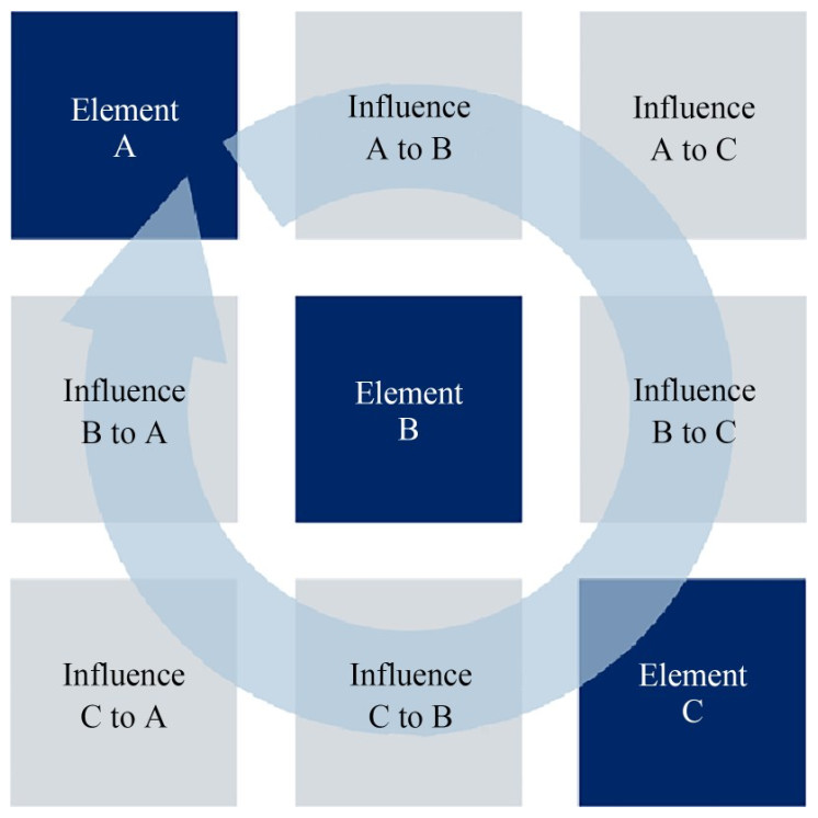 Figure 1 Schematic diagram of the interaction matrix
3.2 Risk matrix assessment
The risk matrix is a qualitative risk assessment tool that combines the likelihood of a risk occurring with the potential impact or severity of its consequences, defined as follows (Condor and Asghari, 2009):
$$ \text{Risk = Possibility × Severity} $$ The visualization of risk interactions can be achieved through the utilization of a risk matrix diagram. In this diagram, the vertical axis corresponds to the likelihood or probability of risk occurrence, whereas the horizontal axis corresponds to the severity or impact of the risks. Using the risk matrix to analyze the interaction between risk factors and evaluate the elements in the interaction matrix, the rational allocation of responsibilities is paramount in defining risks. The values of risk severity and possibility must be determined by experts in combination with the actual situation, and the values of risk possibility and consequence are determined within the numerical range of 1 to 5 to obtain the product of consequences and possibilities within the numerical range of 0 to 25 (Figure 2).
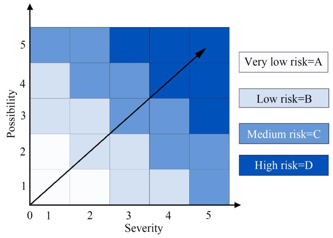 Figure 2 Risk matrix
Following the research conducted by Condor and Asghari (2009), the risk values are divided into four levels, namely, extremely low risk, low risk, medium risk, and high risk. In addition, the unidentified risks and risks that do not affect the entire system are assigned zero values, and these values are used to define the input data of the causal diagram.
3.3 Cause-effect analysis
After the risk values of each interaction are given, as discussed in Section 3.2, the entire system is quantitatively evaluated using the causal diagram. The analysis flow of the causal diagram is as follows: Initially, the values along the diagonal cells are summed separately for the horizontal (causes) and vertical (results) dimensions (Hudson, 1992). In the causal diagram, strength indicates the strength of the interaction, and equidistant lines at an angle of 45° from the axis indicate the strength of the elements. The greater the strength is, the stronger the interaction between elements. The line perpendicular to strength represents the domain of the elements, indicating the scope of the influence of the elements or the objects that they affect. The greater the strength is, the greater the scope of the influence of the elements, the more objects there are, and the more the domains of different elements may overlap. Therefore, the definitions of intensity and domain are expressed as follows:
$$ E_{i \text { intensity }}=\frac{C+E}{\sqrt{2}} $$ (1) $$ E_{i \text { domain }}=\frac{C-E}{\sqrt{2}} $$ (2) Through causal diagram analysis, we can assess the strength and domain values of the elements within the system. Higher strength and larger domain values indicate that these elements play a pivotal role in the system and exert a significant influence on system risk. Consequently, this analysis helps identify the key components of the system and provides robust evidence for constructing risk scenarios.
3.4 Scenario development
The establishment of a CO2 geological storage leakage scenario model is a highly complex process, as numerous FEP can impact CO2 geological storage. Moreover, the selection of FEP for different periods may result in various scenarios. Accordingly, different selections of FEP may lead to varied research outcomes when evaluating CO2 geological leakage during the promotion of a CO2 geological storage project.
When assessing leakage risk in a specific area, relevant elements need to be selected based on the specific characteristics of the area and assign values to the likelihood of element interaction and the severity of potential consequences. Following this, important FEP are identified through causal diagram analysis. Once the key components are determined, the leakage scenario is constructed by integrating the interaction matrix. This comprehensive approach facilitates a more accurate assessment of potential leakage risk in the designated area.
4 Case study
This research focuses on a project situated in the Pearl River Estuary Basin in China, which exhibits substantial carbon sequestration potential, favorable alignment between CO2 sources and storage sites, and a geographically advantageous location. The intended injection volume for this project is 5 million tonnes per year. However, the presence of faults in the storage site necessitated a thorough preinjection risk assessment of the geological CO2 storage system.
4.1 Construction of the target project leakage scenario
4.1.1 Establishment of the interaction matrix
In this study, the main diagonal elements of the interaction matrix represent the components of the OCGS system. Based on the overall stability of the CO2 storage system and the potential pathways for CO2 leakage, this study divides the CO2 storage system of the target project into five distinct components, namely, caprock, reservoir, wellbore composite system (including wellbore, casing, and near-well rock mass), injected CO2, and faults/fractures.
The remaining cells in the interaction matrix define the interactions between these components, which are associated with leakage risk. These interactions are influenced by a multitude of physical and chemical processes, which are characterized by diverse parameters that must be carefully chosen from the FEP database.
By considering expert opinions and analyzing the potential interactions between these components, this study aims to assess the risk of CO2 leakage and understand the factors that contribute to it. This approach helps identify critical areas and design effective mitigation strategies to ensure the safe and reliable storage of CO2 in offshore geological storage systems. The interaction between elements in the interaction matrix is screened and selected from the FEP database developed by Quintessa Company, and based on the research conducted by Condor and Asghari (2009) and Bai et al. (2015), a risk interaction matrix for CO2 leakage from OCGS applicable to this project was established, as shown in Table 1.
Table 1 Interaction matrix for CO2 leakage from OCGS[1, 1] Caprock [1, 2] Sealing [1, 3] Creep [1, 4] Sealing [1, 5] [2, 1] Containment [2, 2] Reservoir [2, 3] Creep [2, 4] Chemical equilibrium dissolution precipitation [2, 5] [3, 1] Load resistance salt dissolution [3, 2] Load resistance sealing [3, 3] Composite system [3, 4] Isolation [3, 5] [4, 1] Seismicity uplift/deformation pressurization advective flow [4, 2] Seismicity uplift/deformation pressurization advective flow dissolution precipitation displacement [4, 3] Seal failure pressurization diffusion corrosion [4, 4] Injected CO2 [4, 5] Instability fault activation [5, 1] [5, 2] [5, 3] [5, 4] Chemical equilibrium dissolution precipitation [5, 5] Fault/fracture 4.1.2 Risk matrix assessment
The analysis of the interaction between risk factors is conducted using a risk matrix, and the FEP in the interaction matrix are evaluated. This assessment process is conducted by a team of experts who consider the specific circumstances of the project, drawing on their expertise and experience to accurately assess the likelihood and severity of the risks involved.
When determining the values of likelihood and severity, the specific situation of the project needs to be considered. The values of risk likelihood and consequence are assigned within the numerical range of 1 to 5, enabling the product of consequence and likelihood to fall within the numerical range of 0 to 25, which represents the risk value. The assignment of each element in the matrix is shown in detail in Figure 3, providing a clear representation of the assessed risk values of the relevant interactions. This approach enables a comprehensive evaluation of the potential risks associated with the CO2 storage system and facilitates the development of appropriate risk mitigation strategies.
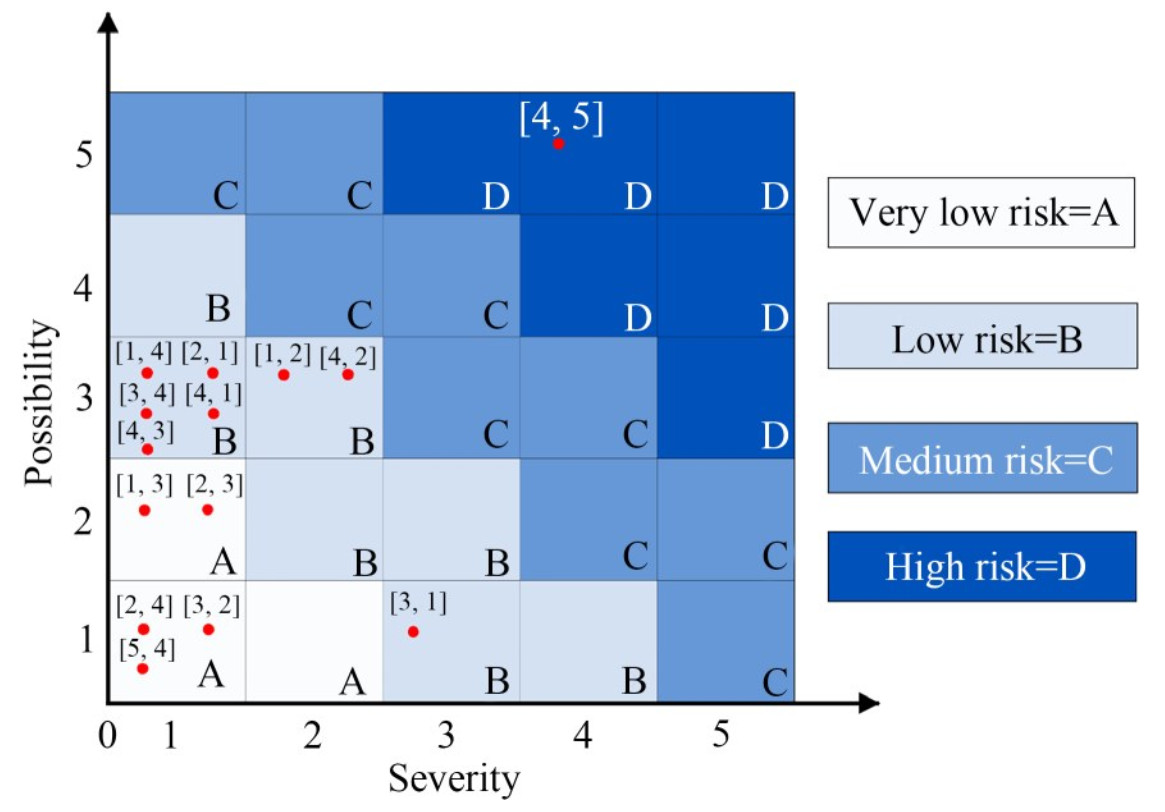 Figure 3 Results of interaction matrix risk assessment
To visually check the risk value of the interaction matrix, each unit of the evaluated matrix is filled with the corresponding color to visualize the risk matrix. As shown in Figure 4, different colors correspond to different risk levels. Notably, zero values are not represented because they do not represent any risk level, and these filled data are used to define the input value of the causal diagram.
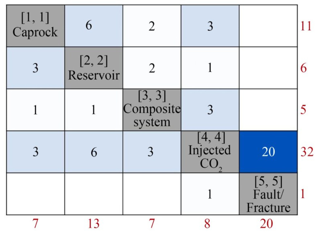 Figure 4 Interaction matrix after assigning the risk value
4.1.3 Cause-effect analysis
Table 2 presents the cause–effect values of all major components of the system, and their domains and strengths were determined based on Equations (1)–(2). The domain value of CO2 injection is the highest (16.97), with the highest strength values corresponding to CO2 injection and faults/fractures (28.28 and 14.85, respectively), as shown in Figure 5. This finding indicates that, during the implementation of this project, the components most significantly influencing leakage are CO2 injection and faults/ fractures.
Table 2 Values of all major components of the systemComponent Cell Cause Effect Domain Intensity Caprock [1, 1] 11 7 2.83 12.73 Reservoir [2, 2] 6 13 4.95 13.44 Composite system [3, 3] 5 7 1.41 8.49 Injected CO2 [4, 4] 32 8 16.97 28.28 Fault/fracture [5, 5] 1 20 13.44 14.85 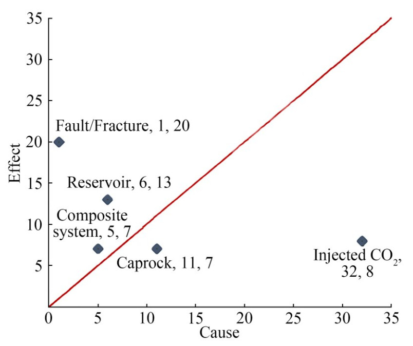 Figure 5 Cause–effect plot
4.2 Scenario development
According to the key components determined by causal diagram analysis and the interaction between components, the CO2 geological storage leakage scenario is constructed according to specific conditions of the project, as follows:
1) An open naturally occurring fault zone or crack is detected in the established reservoir – caprock structure, which connects the storage space with the upper strata. Once the injected CO2 migrates to the fault zone, it migrates upward under the combined action of the density, concentration, and pressure differences, and leakage occurs.
2) The upper and lower plates of the fault slide relative to each other, and the rocks on both sides of the fault are squeezed and staggered, forming a rock fracture zone. The rocks in the fracture zone are loose, forming a water channel with strong water permeability, which provides the conditions for CO2 leakage.
To mitigate leakage risks in the aforementioned scenario, the following measures can be considered:
Phased implementation: Divide the project into different stages and implement them gradually. Each stage should undergo thorough evaluation and validation to ensure the stability and reliability of the previous stage before proceeding to the next stage.
Alternate verification of the construction and grouting plans: During the construction process, alternate verification of the construction and grouting plans should be conducted to ensure the safety and feasibility of the work, as well as the timely identification and resolution of potential issues.
Long-term monitoring of the work area: Set up appropriate monitoring systems to continuously monitor the work area for an extended period, enabling a real-time understanding of the conditions and changes in the area and timely action to be taken as necessary.
Strict design and control of the grouting parameters: Establish strict design and control parameters for the grouting process to ensure that grouting operations comply with safety standards and technical requirements, thereby reducing leakage risk.
Stop injection when risks are severe: Define risk level criteria and immediately halt injection operations once the criteria are met or exceeded. Necessary repairs and adjustments should be made to ensure safety.
Implementing these measures helps reduce leakage risks and ensures the safe operation of the CO2 storage system. In addition, the project team should adhere to relevant laws, regulations, and technical standards, closely cooperate with regulatory authorities, and continuously assess and improve risk management strategies.
5 Application of scenario model construction to risk analysis
5.1 Numerical model
When analyzing a specific project, there are some situations in which the system is complex, the traditional methods cannot be used to analyze or observe, the physical experiment is difficult, the data are difficult to obtain, or the cost is high. Thus, numerical simulation methods, such as CO2 leakage path simulation, failure simulation of closed rock strata in sealed places, and simulation of the impact of CO2 leakage on drinking water, need to be used. In this case, the scenario model can help determine the input parameters needed for numerical simulation, including the initial conditions, boundary conditions, and various parameters. In addition, the scenario model can provide different parameter combinations based on different assumptions and scenarios to simulate and predict different development trends and changes. These scenarios can include different environmental conditions, policy measures, and economic factors to describe and analyze possible changes in the future. By simulating different risk events and scenarios, scenario models can help better evaluate the impact of potential risks and implement the corresponding risk management measures.
In addition, the scenario model can be used to verify the results of numerical simulation. When the result of the numerical simulation is obtained, it can be compared and verified with the prediction of the scenario model to evaluate the accuracy and reliability of the numerical simulation. For example, in the study of the leakage risk of CO2 geological storage, scenario models can describe different leakage situations and CO2 leakage trends under various injection conditions. Meanwhile, in long-term research, numerical simulation can simulate and verify established scenarios and optimize and adjust parameters to improve the accuracy and reliability of scenario models.
5.2 Quantitative evaluation
The establishment of a scenario model can contribute to the quantitative evaluation of risk. Choosing the appropriate quantitative model for the quantitative evaluation of risk, which needs to consider the specific characteristics of the project, the size of the data, the availability of data, and the purpose of the evaluation, is important. Commonly used methods include Monte Carlo simulation, event tree/ event sequence analysis, and probability analysis. Monte Carlo simulation is suitable for the risk assessment of complex systems and multiple variables. Event tree/sequence analysis is used to analyze and evaluate the probability and impact of risk events. It is suitable for risk events with strong traceability and helps understand and predict the development of event chains. Probability analysis is a method based on statistical reasoning that estimates the probability distribution and influence degree of risks through historical data and probability models and is suitable for risk assessment supported by reliable data.
Scenario construction can help determine the most suitable model, better consider different risk factors and events, and provide more accurate results and a decision-making basis for quantitative evaluation.
6 Concluding remarks
OCGS is one of the key measures to reduce greenhouse gas emissions and mitigate climate change. The main risk associated with this technology is CO2 leakage. Therefore, this study proposes a method for establishing OCGS leakage scenarios, which includes four steps, namely, establishing an interaction matrix, evaluating a risk matrix, conducting causal analysis, and developing scenarios. The method is comprehensively applied in a sea area in China, and the main conclusions are as follows:
1) An interaction matrix of the OCGS system is established based on FEP, which mainly includes five system components, namely, layers, reservoirs, wellbore composite system (including wellbore, casing, and near-well rock mass), injected CO2, and faults/fractures, and their interactions.
2) The interactions in the interaction matrix are evaluated using a risk matrix, and a causal graph is drawn based on the results of the risk matrix evaluation. Results show that the key components of the project are injected CO2 (intensity=28.28; domain=16.97) and faults/fractures (intensity=14.85; domain=13.44), which successfully form two potential CO2 geological storage leakage scenarios. The corresponding risk response measures are proposed.
3) The application of scenario modeling to risk analysis is presented, including scenario modeling and quantitative evaluation. Scenario modeling can provide a basis for the establishment of numerical models and verify the results of numerical simulations. For quantitative evaluation, scenario development can help select the appropriate quantitative evaluation models.
The method proposed in this study provides an effective approach for establishing leakage scenarios for OCGS projects, which will play a positive role in promoting the sustainable development and safe operation of OCGS projects. In the future, this method can be further improved and applied to meet the needs of leakage scenario establishment and management in different geographical environments and project requirements.
Competing interest The authors have no competing interests to declare that are relevant to the content of this article. -
Figure 1 Schematic diagram of the interaction matrix
Figure 2 Risk matrix
Figure 3 Results of interaction matrix risk assessment
Figure 4 Interaction matrix after assigning the risk value
Figure 5 Cause–effect plot
Table 1 Interaction matrix for CO2 leakage from OCGS
[1, 1] Caprock [1, 2] Sealing [1, 3] Creep [1, 4] Sealing [1, 5] [2, 1] Containment [2, 2] Reservoir [2, 3] Creep [2, 4] Chemical equilibrium dissolution precipitation [2, 5] [3, 1] Load resistance salt dissolution [3, 2] Load resistance sealing [3, 3] Composite system [3, 4] Isolation [3, 5] [4, 1] Seismicity uplift/deformation pressurization advective flow [4, 2] Seismicity uplift/deformation pressurization advective flow dissolution precipitation displacement [4, 3] Seal failure pressurization diffusion corrosion [4, 4] Injected CO2 [4, 5] Instability fault activation [5, 1] [5, 2] [5, 3] [5, 4] Chemical equilibrium dissolution precipitation [5, 5] Fault/fracture Table 2 Values of all major components of the system
Component Cell Cause Effect Domain Intensity Caprock [1, 1] 11 7 2.83 12.73 Reservoir [2, 2] 6 13 4.95 13.44 Composite system [3, 3] 5 7 1.41 8.49 Injected CO2 [4, 4] 32 8 16.97 28.28 Fault/fracture [5, 5] 1 20 13.44 14.85 -
AI-Traboulsi M, Sjögersten S, Colls J, Steven M, Craigon J, Black C (2012) Potential impact of CO2 leakage from carbon capture and storage (CCS) systems on growth and yield in spring field bean. Environmental and Experimental Botany 80: 43-53. https://doi.org/10.1016/j.envexpbot.2012.02.007 Arild Ø, Ford EP, Lohne HP, Majoumerd MM, Havlova V (2017) A comparison of FEP-analysis and barrier analysis for CO2 leakage risk assessment on an abandoned czech oilfield. Energy Procedia 114: 4237-4255. https://doi.org/10.1016/j.egypro.2017.03.1564 Bai MX, Song KP, Li Y, Sun JP, Reinicke KM (2015) Development of a novel method to evaluate well integrity during CO2 underground storage. SPE Journal 20(3): 628-641. https://doi.org/10.2118/173000-Pa Berrouane MT, Lounis Z (2016) Safety assessment of flare systems by fault tree analysis. Journal of Chemical Technology and Metallurgy 51(2): 229-234. Blackford J, Alendal G, Avlesen H, Brereton A, Cazenave PW, Chen B, Dewar M, Holt J, Phelps J (2020) Impact and detectability of hypothetical CCS offshore seep scenarios as an aid to storage assurance and risk assessment. International Journal of Greenhouse Gas Control 95: 102949. https://doi.org/10.1016/j.ijggc.2019.102949 Bobbio A, Portinale L, Minichino M, Ciancamerla E (2001) Improving the analysis of dependable systems by mapping fault trees into Bayesian networks. Reliability Engineering & System Safety 71(3): 249-260. https://doi.org/10.1016/S0951-8320(00)00077-6 Bourne S, Crouch S, Smith M (2014) A risk-based framework for measurement, monitoring and verification of the Quest CCS Project, Alberta, Canada. International Journal of Greenhouse Gas Control 26: 109-126. https://doi.org/10.1016/j.ijggc.2014.04.026 Boyd AD, Liu Y, Stephens JC, Wilson EJ, Pollak M, Peterson TR, Einsiedel E, Meadowcroft J (2013) Controversy in technology innovation: Contrasting media and expert risk perceptions of the alleged leakage at the Weyburn carbon dioxide storage demonstration project. International Journal of Greenhouse Gas Control 14: 259-269. https://doi.org/10.1016/j.ijggc.2013.01.011 Condor J, Asghari K (2009) An alternative theoretical methodology for monitoring the risks of CO2 leakage from wellbores. Energy Procedia 1(1): 2599-2605. https://doi.org/10.1016/j.egypro.2009.02.026 Dewar M, Saleem U, Flohr A, Schaap A, Strong J, Li J, Roche B, Bull JM, Chen B, Blackford J (2021) Analysis of the physicochemical detectability and impacts of offshore CO2 leakage through multi-scale modelling of in-situ experimental data using the PLUME model. International Journal of Greenhouse Gas Control 110: 103441. https://doi.org/10.1016/j.ijggc.2021.103441 Flett M, Brantjes J, Gurton R, McKenna J, Tankersley T, Trupp M (2009) Subsurface development of CO2 disposal for the Gorgon Project. Energy Procedia 1(1): 3031-3038. https://doi.org/10.1016/j.egypro.2009.02.081 Hudson JA (1992) Rock engineering systems: theory and practice. Ellis Horwood Ltd., London IPCC (2007) Climate change 2007: synthesis report. IPCC, Geneva, Switzerland, Report No. 92-9169-122-4 Jiang X (2011) A review of physical modelling and numerical simulation of long-term geological storage of CO2. Applied Energy 88(11): 3557-3566. https://doi.org/10.1016/j.apenergy.2011.05.004 Jiao Y, Hudson JA (1995) The fully-coupled model for rock engineering systems. International Journal of Rock Mechanics and Mining Sciences & Geomechanics Abstracts 32(5): 491-512. https://doi.org/10.1016/0148-9062(95)00038-i Kanberoğlu B, Turan E, Kökkülünk G (2023) Decarbonization of maritime transportation: a case study for Turkish ship fleet. Journal of Marine Science and Application 22: 716-727. https://doi.org/10.1007/s11804-023-00370-6 Kapetaki Z, Hetland J, Le Guenan T, Mikunda T, Scowcroft J (2017) Highlights and lessons from the EU CCS demonstration project network. Energy Procedia 114: 5562-5569. https://doi.org/10.1016/j.egypro.2017.03.1696 Lackner KS (2003) A guide to CO2 sequestration. Science 300(5626): 1677-1678. https://doi.org/10.1126/science.1079033. Li Q, Liu G (2016) Risk assessment of the geological storage of CO2: a review. Geologic Carbon Sequestration: Understanding Reservoir Behavior, 249-284. https://doi.org/10.1007/978-3-319-2709-7_13 Li Q, Liu G, Cai B, Leamon G, Liu LC, Chen Z, Li X (2017) Public awareness of the environmental impact and management of carbon dioxide capture, utilization and storage technology: the views of educated people in China. Clean Technologies and Environmental Policy 19(8): 2041-2056. https://doi.org/10.1007/s10098-017-1387-0 Meissner P, Brands C, Wulf T (2017) Quantifiying blind spots and weak signals in executive judgment: a structured integration of expert judgment into the scenario development process. International Journal of Forecasting 33(1): 244-253. https://doi.org/10.1016/j.ijforecast.2015.08.002 Miocic JM, Gilfillan SMV, Roberts JJ, Edlmann K, McDermott CI, Haszeldine RS (2016) Controls on CO2 storage security in natural reservoirs and implications for CO2 storage site selection. International Journal of Greenhouse Gas Control 51: 118-125. https://doi.org/10.1016/j.ijggc.2016.05.019 Paul JHS (1993) Multiple scenario development: Its conceptual and behavioral foundation. Strategic Management Journal 14(3): 193-213. https://doi.org/10.1002/smj.4250140304 Paulley A, Metcalfe R, Limer L (2011) Systematic FEP and scenario analysis to provide a framework for assessing long-term performance of the Krechba CO2 storage system at In Salah. Energy Procedia 4: 4185-4192. https://doi.org/10.1016/j.egypro.2011.02.365 Pruess K (2008) Leakage of CO2 from geologic storage: Role of secondary accumulation at shallow depth. International Journal of Greenhouse Gas Control 2(1): 37-46. https://doi.org/10.1016/S1750-5836(07)00095-3 Sandoval N, Reyna JL, Landis AE (2023) Internal consistency and diversity scenario development: a comparative framework to evaluate energy model scenarios. Renewable and Sustainable Energy Reviews 186: 113632. https://doi.org/10.1016/j.rser.2023.113632 Son K, Choi K, Yang J, Jeong H, Kim H, Chang K, Heo G (2023) A review of the features, events, and processes and scenario development for Korean risk assessment of a deep geological repository for high-level radioactive waste. Nuclear Engineering and Technology 55(11): 4083-4095. https://doi.org/10.1016/j.net.2023.07.027 Walke R, Metcalfe R, Limer L, Maul P, Paulley A, Savage D (2011) Experience of the application of a database of generic Features, Events and Processes (FEP) targeted at geological storage of CO2. Energy Procedia 4: 4059-4066. https://doi.org/10.1016/j.egypro.2011.02.348 Yamaguchi K, Takizawa K, Shiragaki O, Xue Z, Komaki H, Metcalfe R, Yamaguchi M, Kato H, Ueta S (2013) Features events and processes (FEP) and scenario analysis in the field of CO2 storage. Energy Procedia 37: 4833-4842. https://doi.org/10.1016/j.egypro.2013.06.393 Yavuz F, Van Tilburg T, David P, Spruijt M, Wildenborg T (2009) Second generation CO2 FEP analysis: CASSIF - carbon storage scenario identification framework. Energy Procedia 1(1): 2479-2485. https://doi.org/10.1016/j.egypro.2009.02.010 Zhang L, Zhang S, Jiang W, Wang Z, Li J, Bian Y (2018) A mechanism of fluid exchange associated to CO2 leakage along activated fault during geologic storage. Energy 165: 1178-1190. https://doi.org/10.1016/j.energy.2018.09.104 Zhang Y, Oldenburg CM, Finsterle S, Jordan P, Zhang K (2009) Probability estimation of CO2 leakage through faults at geologic carbon sequestration sites. Energy Procedia 1(1): 41-46. https://doi.org/10.1016/j.egypro.2009.01.008
