
Integrated System of Semi-submersible Offshore Wind Turbine Foundation and Porous Shells
https://doi.org/10.1007/s11804-024-00406-5
-
Abstract
A novel semi-submersible platform is proposed for 5 MW wind turbines. This concept focuses on an integrated system formed by combining porous shells with a semi-submersible platform. A coupled aerodynamic–hydrodynamic–mooring analysis of the new system is performed. The motion responses of the novel platform system and the traditional platform are compared. The differences in hydrodynamic performance between the two platforms are also evaluated. The influence of the geometric parameters (porosity, diameter, and wall thickness) of porous shells on the motion response behavior of the new system is studied. Overall, the new semi-submersible platform exhibits superior stability in terms of pitch and heave degrees of freedom, demonstrating minimal effects on the motion response in the surge degree of freedom.Article Highlights● A coupled aerodynamic-hydrodynamic-mooring analysis was considered.● The motion response of the integrated system was characterized.● The integrated porous shell can improve the hydrodynamic performance offshore wind turbine. -
1 Introduction
Countries around the world are making a concerted effort to develop clean energy due to the shortage of fossil energy sources and pollution problems. For example, nuclear, wind, and wave power are continuously developed at an accelerated rate. In recent years, owing to its safety, controllability, low cost, and large development potential, wind energy has gradually become the object of vigorous development in various countries.
A wide variety of offshore wind research projects and development programs have been proposed (Gaudiosi, 1996). Numerous studies and surveys revealed that the United States, China, and Europe all have large offshore wind energy potential (Gaudiosi, 1994; GWEC, 2023). Moreover, the installed capacity and power generation by offshore wind turbines have been rapidly increasing (Wang et al., 2015). From a practical perspective, the development of offshore wind energy has numerous advantages. In addition to the advantages of safety, reliability, and low environmental impact, offshore wind also has improved stability, transmission efficiency, long generation times, and a highly stable power output (Cutler et al., 2022). Based on the different forms of installation, offshore wind turbines can be categorized as fixed or floating. The former and latter categories are suitable for deployment in shallow and deep water areas, respectively. The distribution density of wind turbines in near-shore areas is gradually becoming saturated, and the siting of future wind farms will gradually transition into deep water locations (Loughney et al., 2021).
One of the main challenges for floating wind turbines lies in limiting the motion response to an acceptable dynamic range (Jonkman and Buhl, 2007). Current research and design goals of numerous scholars for floating platforms are based on two main criteria: cost reduction and stability improvement. Considering improvements in stability, the largest concern focuses on limiting the pitching motion (Edwards et al., 2023). The platforms used for floating wind turbines are currently broadly categorized into four types: barges, semi-submersible platforms, spar platforms, and tension leg platforms (Uzunoglu and Guedes Soares, 2020). The use of semi-submersible platforms as support foundations for offshore floating wind turbines is a popular choice due to their satisfactory wave energy dissipation performance and improved motion stability characteristics (Liu, 2016). Therefore, a semi-submersible floating platform will be chosen in this research as the base prototype for investigating the motion response.
The coupling effects of multiple environmental factors must be considered during the design process to accurately simulate the complex environment in which floating platforms operate. These effects include aerodynamic loading, hydrodynamic loading, and mooring loads. Several conventional research methods include physical experiments, numerical simulation approaches, and theoretical calculations. Of the three analysis methods, physical experiments provide the highest accuracy and reliability. However, the high costs associated with wind turbine experiments are demanding. Therefore, the accuracy of the numerical models is often verified using the results of physical model experiments (Nielsen et al., 2006). The accuracy of the numerical model will be verified in this study by comparing the data from the physical model with experiments.
Software programs used to perform hydrodynamic analyses on offshore wind turbines are generally based on the three-dimensional potential flow theory combined with the Morison equation and diffraction radiation theory. AQWATM, WAMITTM, and SESAMTM are examples of these software programs (Zou et al., 2023). Soeb et al. (2017) conducted a motion response analysis on a spar platform in ultradeep sea conditions using ABAQUS/AQWATM. They found a reduction in the motion response of a platform in heave and pitch degrees of freedom due to the current force. Meanwhile, an intensification of the mooring line damping and a significant reduction in the motion response of the platform are observed with the increase in water depth. Zhang et al. (2020b) conducted a hydrodynamic analysis, including second-order hydrodynamic effects on three different types of wind turbines with semi-submersible foundations. They found a larger modeled motion response of a semi-submersible platform than the actual motion response when the viscous damping effect on the platform is avoided. The second-order wave force substantially affects the motion response in terms of the pitch degree of freedom of the platform. Zhang et al. (2020b) considered the second-order hydrodynamic effects but neglected factors such as aerodynamic loading.
A common and effective method to improve the motion characteristics of the floating offshore wind turbine involves structural innovations to the support platform of the wind turbine. Yu et al. (2015) investigated the motion characteristics of a spar platform, including the coupled effects of wind – wave loading, and provided crucial data for engineering applications. They analyzed the hydrodynamic characteristics of the platform and the dynamic response of the turbine using the FFT method and discussed the effects of wind and wave loads on the integrated turbine–platform system. Ding et al. (2019) introduced a system comprising a spar-type platform coupled with a heave plate. The boundary element approach was employed to investigate the influence of the heave plate in combined aerodynamic and hydrodynamic loading scenarios. They found that the different positions of the heave plate affected the platform motion response. The motion response in the pitch and heave degrees of freedom was effectively reduced and had minimal influence on the surge degree of freedom when the heave plate was attached to the upper part of the spar. Zhang et al. (2020a) designed a Ⅴ-shaped floating wind turbine platform including a mooring line system at a water depth of 50 m. They performed a fully coupled analysis based on aero-hydro-servo-elastic effects. Zhao et al. (2021) also introduced a semi-submersible platform for medium water depths and compared its motion response characteristics with the LIFES 50+OO-Star platform. Their results demonstrated that the proposed new platform achieved good stability. Numerous scholars only consider the variation of a single environmental loading factor when investigating the hydrodynamic response of platforms to simplify the computational complexity. Yang et al. (2020) investigated 22 cases of regular wave conditions and steady-state winds in their study on the hydrodynamic response of the OC3-Hywind platform. Zhou et al. (2021) studied the effects of wave height and frequency on the hydrodynamic response of a barge-type platform using ANSYS AQWATM by adopting six regular wave conditions in their analyses. Similarly, a single environmental loading parameter is varied in this research, while other loading conditions are fixed. Specifically, a single incident wave height with a range of different frequencies and steady-state wind speeds is selected. Yao et al. (2023) published a study on porous shells integrated with the OC3-HyWind platform system. They considered the influence of a porous shell on the platform motion response and hydrodynamic coefficients and found improvements in the motion characteristics in the heave degree of freedom (DOF) due to the porous shells. Vaezi et al. (2021) effectively inhibited the motion of the conduit rack-type platform using viscous dampers. Jiang et al. developed a spar-type floating wind turbine, namely SJTU-S4, for medium to shallow water depths. This platform achieves good hydrodynamic performance by combining the advantages of a stabilizing heave plate, a semi-submersible platform, and a spar platform (Jiang et al., 2021). Zhang et al. (2020b) studied the hydrodynamic characteristics of three different types of semi-submersible platforms (OC4-DeepCwind, Ⅴ-shaped semi-submersible, and braceless semi-submersible) in water depths of 100 and 200 m. They also considered and compared the effect of drag on the motion response of the platforms. Wave load-reducing porous shells were incorporated in this study into the design of an OC4-DeepCwind platform, thereby extending Yao et al. (2023).
This study presents an integrated system comprising an OC4-DeepCwind semi-submersible platform coupled with three concentric porous shells surrounding each of the platform hulls. A hydrodynamic load analysis was performed on the platform in the frequency domain using ANSYS AQWATM (ANSYS AQWA, 2016). The OpenFAST© Software was used to examine the fully coupled aerodynamic–hydrodynamic – mooring, time-domain numerical simulation (Jonkman, 2020). The data results were compared with those of the OC4-DeepCwind semi-submersible platform without any attached porous shells to investigate the motion response performance of the new platform. The rest of this paper is organized as follows: The structural form of the integrated system is described in Section 2. The numerical simulation methods, theoretical foundations, and validation processes are presented in Section 3. The results of the numerical simulations are provided in Section 4, and the results of the study are summarized in Section 5.
2 Description of the integrated system
2.1 Configuration of the integrated system
The new platform design in this study is based on the modified traditional OC4-DeepCwind platform. This platform comprises three interconnected cylindrical hulls arranged in a triangular plan layout. The main column, which is connected to the hulls via pontoons and cross braces, is positioned at the center of the platform, supporting the wind turbine tower. Table 1 and Figure 1(a) show the structural details of the traditional platform (Benitz et al., 2014). The novel integrated system comprising the OC4-DeepCwind platform with three porous shells concentric around the hulls is depicted in Figure 1(b). The porous shells, which have an outer diameter D, wall thickness d, and draft h, are fixed to each of the platform hulls to form the new design. The porosity of the shells is calculated using the following: τ =$ \frac{n {\rm{ \mathsf{ π}}} r^2}{S}$, where r is the radius of the circular holes, n is the number of holes, and S is the total surface area of the shell without any voids. The tops of the porous shells are positioned 2 m above the static water surface. The draft of the porous shells is h = 4 m. The outer diameter of the porous shells is D = 20 m. The wind turbine is designated as a 5 MW capacity model to facilitate the subsequent validation and analysis. Tables 2 and 3 list the novel platform and the dimensions of the porous shells, respectively.
Depth of platform base below still water line 20 Centerline spacing between offset columns 50 Length of upper columns 26 Length of base columns 6 Diameter of main columns 6.5 Diameter of offset columns 12 Diameter of base columns 24 Diameter of pontoons and cross braces 1.6 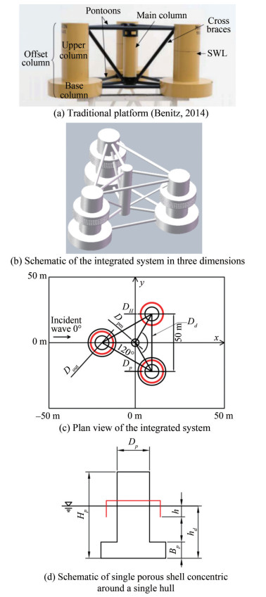 Figure 1 Integrated system comprising the OC4-DeepCwind with three porous shellsTable 2 Novel porous shell integrated platform dimensions
Hull diameter Dp (m) 12 Heave plate diameter DH (m) 24 Center column diameter Dpm (m) 6.5 Bracing diameter Dd (m) 1.6 Total platform height Hp (m) 32 Operating draft hd (m) 19.36 Height of damping plate BP (m) 6 Displacement (kg) 1.347 3×10⁷ Table 3 Porous shell dimensionsPorosity τ 0.3 Outer diameter Dout (m) 20 Wall thickness d (m) 0.5 Total height H (m) 6 Operating draft h (m) 4 2.2 Mooring system
For the modified OC4-DeepCwind platform with porous shells, the mooring system comprises three mooring cables arranged in a radial configuration with a separation angle of 120° between each cable. One cable is aligned along the negative X-axis in the model. The mooring lines attach to the floating platform hulls 14 m underwater. At a horizontal distance of 797 m from the platform attachment point, the anchor points are at a depth of 200 m underwater. The mooring line has a diameter of 0.076 6 m and an approximate length of 835 m.
3 Floating platform load calculation model
3.1 Coupling framework
Complex coupled effects are produced by the application of aerodynamic and hydrodynamic loads and are processed through the synergistic integration of the AeroDyn, MoorDyn, ANSYS AQWA, and OpenFAST© software. Previous work extensively described the coupled calculation method, and the reader is directed to an earlier publication for further details of the coupled dynamic analysis process (Yao et al., 2023).
3.2 Fully coupled equations of motion
The governing equations for the fully coupled time-domain computational model can be expressed as follows (Jonkman, 2007):
$$ \boldsymbol{M}_{i j}(x, v, t) \ddot{x}_{i j}=\boldsymbol{F}_i $$ (1) $$ F=F_{\mathrm{Air}}+F_{\mathrm{HR}}+F_F+F_B+F_M $$ (2) where Mij is the inertial mass, and i is the degree of freedom. $ \ddot{x}_{i j}$, x, and x denote the acceleration, velocity, and motion vectors, respectively; v is the wind turbine control input (Ning et al., 2015); t is time, and F is the total load. The aerodynamic loads, the linear hydrostatic restoring forces, the wave-exciting loads, the radiation loads (which include the effects of added mass and radiation damping), and the mooring loads are denoted by FAir, FHR, FF, FB, and FM, respectively. The following subsections examine these component loads.
3.3 Aerodynamic loads
The calculation of the aerodynamic loads utilizes blade element and momentum theories (Moriarty and Hansen, 2005). Blade element theory indicates the division of wind turbine blades into a number of independent segments or blade elements. The total load on the turbine blades for one rotor revolution is obtained by calculating and summarizing the aerodynamic load for each blade element. This approach has some limitations; for example, the blade element method disregards the tip loss effects induced by air vortices generated near the blade ends. Furthermore, each annular ring is independent of other annular rings in the computation process, and interference between the turbine blades is generally neglected. Momentum theory assumes that the momentum and pressure loss in the plane of the rotor originate from the aerodynamic planar airflow. Using the momentum theory, aerodynamic loads on the turbine blades can be computed through the iterative process. Regardless of the limitations of the blade element and momentum theory approaches, the most commonly adopted approach for the design and analysis of wind turbines is the blade element momentum method (Moriarty and Hansen, 2005). Considering this method, the load computed on each blade can be divided into thrust and torque loads.
The thrust loads can be calculated in accordance with the following:
$$ T=\int \frac{1}{2} \rho_a V^{\prime 2}\left(C_L \cos \theta+C_D \sin \theta\right) c \mathrm{~d} r $$ (3) The torque loads can be calculated from the following:
$$ Q=\int \frac{1}{2} \rho_a V^{\prime 2}\left(C_L \sin \theta-C_D \sin \theta\right) c \mathrm{~d} r $$ (4) where the thrust and moment loads acting on a single blade element are denoted by T and Q, respectively; the air inflow angle is expressed by θ; the distance between the airfoil section and blade root is denoted by r; the air density is denoted by ρa; the airfoil chord length is denoted by c; the relative wind speed is denoted by V'; and the lift and drag coefficients are denoted by CL and CD, respectively.
3.4 Hydrodynamic loads
The linear hydrostatic restoring force FHR, the incident wave excitation force FF and the radiation force FB are the main categories of hydrodynamic loads on floating platforms.
The first-order exciting force can be calculated in accordance with the following (Faltinsen, 1990):
$$ F_F(t)=\frac{1}{2 {\rm{ \mathsf{ π}}}} \int_{-\infty}^{+\infty} f(\omega) \sqrt{2 {\rm{ \mathsf{ π}}} S(\omega)} X_i \mathrm{e}^{\mathrm{j} \omega t} \mathrm{~d} \omega $$ (5) where j = $ \sqrt{-1}$; S is the power spectral density, ω is the circular frequency, f is the Fourier transform, and Xi denotes the components in different degrees of freedom.
The radiation force includes the effects of added mass (Aij) and radiation damping (Bij), and it is given by:
$$ F_B=-\int_{-\infty}^t R(t-\alpha) \dot{x}(\alpha) \mathrm{d} \alpha $$ (6) where R (t) is the retardation function:
$$ R(t)=-\frac{2}{{\rm{ \mathsf{ π}}}} \int_0^{\infty} b(\omega) \cos (\omega t) \mathrm{d} \omega $$ (7) where b is the linear radiation damping.
The linear hydrostatic restoring force is calculated from (Zhao et al., 2016):
$$ F_{\mathrm{HR}}=\rho_w g V_0 v_{i 3}-C_{i j} x_j(t) $$ (8) where V0 is the initial displacement of the fluid; ν is the component of the Kronecker delta function and is non-zero only when the DOF i = 3; and Cij is the linearized hydrostatic restoring coefficient.
3.5 Mooring loads
The MoorDyn program is selected in this study for the calculation of the mooring forces. A lumped-mass approach is employed by MoorDyn to discretize the cable dynamics over the length of the mooring line, thereby demonstrating its efficiency and accuracy for calculating mooring forces (Hall, 2015). The mooring design typically uses the lumped-mass approach. The mooring force on the cable is obtained by solving the loads on each discretized mass section and summing the loads at each mass point. The axial elastic and damping forces on the cable, gravity and buoyancy forces on the cable, hydrodynamic forces based on the Morison formula, and vertical elastic and damping forces from contact with the seabed are the loads to be considered at each mass point.
3.6 Model verification and validation
3.6.1 Mesh convergence analysis
The wave conditions used for the validation study comprise a monochromatic wave with f = 0.06 Hz, H = 4 m, and β = 0°. A number of different grid densities, including coarse (number of cells is 12 058), medium (number of cells is 22 370), and fine (number of cells is 26 765), were selected. A comparison of the motion response curves in the surge and heave is performed using the different grid densities. The results demonstrated convergence when the number of grid cells exceeded 20 000. Figure 2 presents the grid distribution for the platform and the porous shells. The number of cells in the final selected case in this study is 22 370, of which the platform is defined by 7 247 cells, and the surface of porous shells is represented by 15 123 cells.
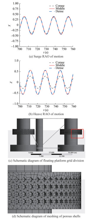 Figure 2 Mesh convergence analysis and grid distribution schematic
3.6.2 Validation of the hydrodynamic loads on the solid cylinder with the porous shell
A comparison of the obtained results in this study with those published by Mackay et al. (2021) confirmed the accuracy of the hydrodynamic coefficient calculations for the porous shells. Figure 3 shows the model used for validation, that is, a vertical solid cylinder with a fixed base surrounded by a concentric porous shell. The diameter and the water depth of the solid cylinder are 250 and 1 000 mm, respectively. The porous shell (τ=0.2) with a diameter of 375 mm is located on the outside of the solid cylinder. Validation is performed by comparing the numerical and experimental results of wave forces on the circular cylinder subjected to regular waves.
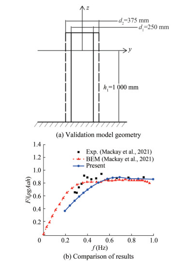 Figure 3 Comparison of the wave forces on the cylinder with different analysis methods
3.6.3 Validation of the hydrodynamic coefficients
The hydrodynamic effects due to the wave interaction with the semi-submersible platform are divided into the following three main components: added mass (A'ij), radiation damping (B'ij) values, and first-order exciting forces and moments (Fi and Mi, respectively). The calculation of the added mass and radiation damping coefficients is as follows:
$$ A_{i j} =\frac{A_{i j}^{\prime}}{\rho L^k} $$ (9) $$ B_{i j} =\frac{B_{i j}^{\prime}}{\rho L^k \omega} $$ (10) where Aij and Bij are the added mass and radiation damping coefficients, respectively. A'ij and B'ij are the added mass and radiation damping values, respectively. L = 12 m is the diameter of the cylinder, k = 3 for i, j = 1, 2, 3, k = 5 for i, j = 4, 5, 6, and ω is the wave circular frequency. As shown in Figures 4 and 5, the added mass, radiation damping, exciting forces, and moments in dimensionless form are compared with the results obtained from WAMIT (Coulling et al., 2013), respectively. The results reveal good agreement between the two methods.
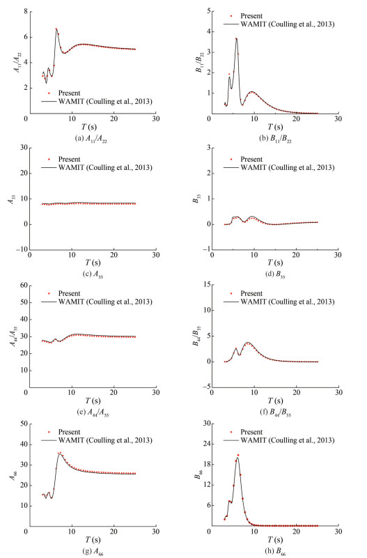 Figure 4 Comparison of added mass and radiation damping with WAMIT
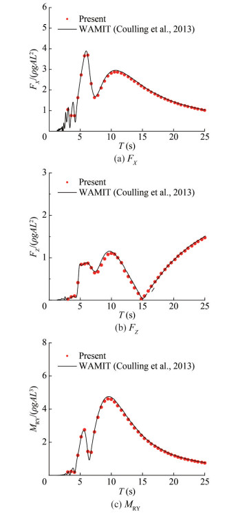 Figure 5 Comparison of excitation forces FX, FZ and moment MRY with WAMIT
4 Result and discussions
The frequency range of the regular incident wave is 0.04–0.25 Hz, the wave height is 4 m, the water depth is 200 m, and the wind speed is set at 8 m/s in the typical working environment. The present numerical modeling study adopts these conditions.
4.1 Influence of porous shell on the motion response of the platform
In addition to the added mass and the radiation damping effects, the motion response of the platform depends on the loads acting on it. The motion response of the platform is affected by the integration of the porous shells with the platform. Figure 6 shows that "OC4" and "OC4 with porous shells" indicate the traditional and novel platforms proposed in this paper, respectively.
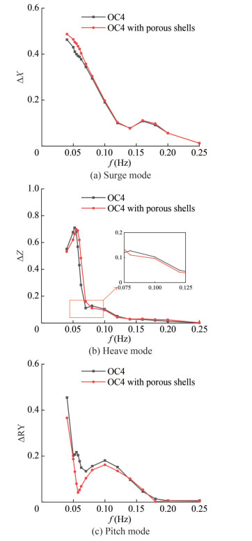 Figure 6 Comparison of motion responses in surge, heave, and pitch modes with porous shells
Figure 6 shows the three main DOF motion responses of the platform. The incident wave angle is 0° in all cases. The motion responses for the case of the platform with and without the porous shells attached are compared. Figure 6(a) reveals the occurrence of the maximum motion response in surge at the lowest investigated frequency for cases with and without porous shells. As the wave frequency increases, the motion response generally decreases. A local peak is observed near 0.16 Hz. A slight increase in the motion response of the platform at low frequency wave conditions can be attributed to the porous shells. The addition of porous shells intensifies the applied force area of the platform, thereby increasing the applied wave loads on the platform.
Figure 6(b) shows that the peak heave motion response frequency of the platform is affected by the attachment of the porous shells. The peak shifts toward a high frequency, and the magnitude of the peak value slightly decreases. The porous shells also act as a motion suppressor at approximately 0.08 – 0.12 Hz (around the second peak), demonstrating a reduction of approximately 16%.
Figure 6(c) shows that the motion response of the platform in the pitch DOF is markedly influenced by the porous shells. The maximum motion response is observed at the lowest frequency, with and without the porous shell. A considerable reduction in the motion response amplitude is observed when the porous shell is attached. The reduction in the pitch motion response at the lowest frequency is approximately 19.5% when the porous shell is attached. Local peak values are found at 0.05 and 0.1 Hz in the case of the platform without the porous shell. The local peak value at 0.05 Hz is eliminated after the incorporation of the porous shells in the model. Considerable suppression of the motion response is realized near the wave frequency of 0.1 Hz, demonstrating an 11% reduction in the pitch motion response. Furthermore, the maximum pitch motion suppression achieved over the entire wave frequency range is 79% (at 0.057 5 Hz).
Overall, these results indicate that the addition of the porous shells effectively improves the dynamic stability of the floating offshore wind turbine platform.
Figure 7 shows the excitation forces in the three main DOFs. The excitation force magnitudes are influenced by the integration of the porous shells, but such an integration has minimal effect on the peak frequencies.
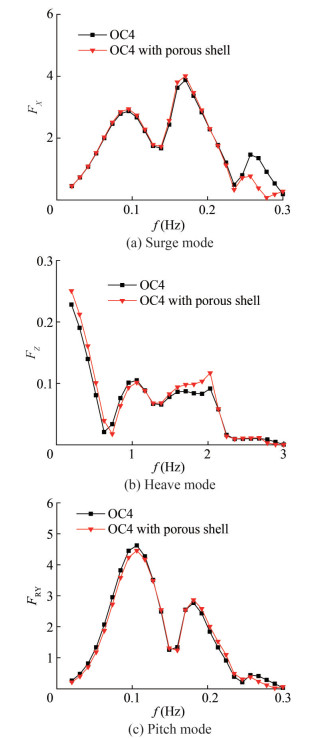 Figure 7 Comparison of excitation forces and moment on the platform with and without porous shells
Figure 7(a) indicates that the surge excitation force on the platform with the porous shells does not increase significantly in the low frequency band (0–0.1 Hz). When the porous shell is attached, the magnitude of the surge excitation forces slightly increases at the first and second peak frequencies, but the wave peak frequency values remain unchanged. The surge excitation forces are significantly reduced in the case of the porous shell system at the high-frequency band, and notable load reductions are realized. Figure 7(b) shows a slightly greater low frequency heave excitation force on the integrated platform than that applied to the platform without the porous shell. Simultaneously, a slight frequency shift at the first trough to a higher frequency is observed. A slight reduction in the heave excitation force for the integrated platform is observed between the first local minimum force value and the first local maximum value. A significant increase in the heave exciting force applied to the integrated platform is also observed at f = 0.2 Hz. Figure 7(c) reveals that the integration of porous shells facilitates a moment reduction under low frequency wave conditions. A slight reduction is observed in the first peak. Simultaneously, the incorporation of the porous shells also leads to a reduction in the excitation moment in the high-frequency region (f = 0.25 Hz).
Overall, the excitation force on the platform can be improved to some extent by the integrated porous shells. In low-frequency wave conditions, the main influences are observed in the heave and pitch DOF, while those in high-frequency wave conditions are found in the surge DOF. In the heave DOF, the inclusion of the porous shells raises the excitation force in mid-frequency wave conditions, revealing a notable increase of around 0.2 Hz.
In addition to the excitation force, the added mass and radiation damping effects also strongly influence the motion response of the platform. Figure 8 shows the added mass and the radiation damping of the platform in the three main DOFs.
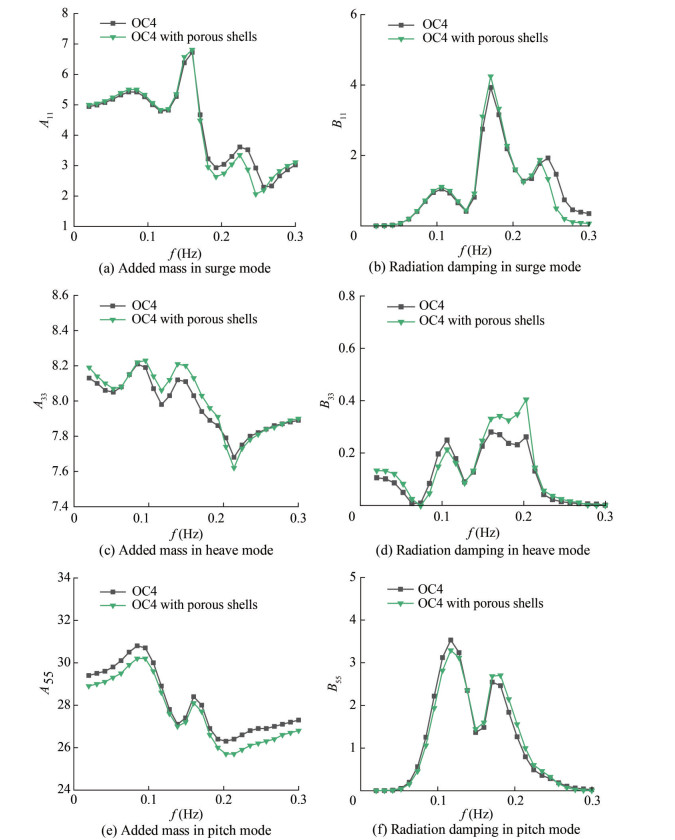 Figure 8 Comparisons of added mass and radiation damping in different modes with and without porous shells
Figure 8(a) shows a small increase in surge added mass in the low frequency range in the platform with the porous shells attached. However, the added mass of the integrated platform is lower than that of the original, unmodified OC4 platform when the frequency rises above 0.18 Hz. The attachment of the porous shell results in a high surge added mass in the high frequency range (f > 0.25). Figure 8(c) reveals a significant increase in the added mass of the integrated platform for all frequencies less than 0.18 Hz. The influence of the porous shells on the heave added mass is slightly pronounced at frequencies above 0.18 Hz. Figure 8(e) shows that adding porous shells aims to reduce the pitch added mass throughout the range of wave frequencies investigated. Figure 8(b) shows the notable effect of the porous shell on the surge radiation damping near the middle and high frequencies. At 0.17 Hz, an increase in the maximum peak value of radiation damping can be attributed to the addition of the porous shells. Moreover, high frequencies (f > 0.23 Hz) demonstrate a reduction in radiation damping. Figure 8(d) reveals a similar trend of the radiation damping results for the integrated platform in heave DOF to the heave excitation force results. The radiation damping increases in the ranges of 0.02–0.07 and 0.15–0.3 Hz but decreases in the 0.07–0.15 Hz range. Figure 8(f) shows that incorporating porous shells reduces the value of the first pitch radiation damping peak and increases the value of the second peak.
4.2 Effect of different parameters of porous shells
Section 4.1 concludes the effectiveness of porous shells in improving the stability of the floating platform. The effect of the parameters of porous shells will then be investigated from three different geometrical aspects: porous shell wall thickness, the radius of the porous shells, and the porosity of the porous shells. Figure 9 shows that "OC4" and "OC4 with porous shells (d = 1 m)" indicate the traditional platform and a new platform with porous shells having a wall thickness of 1 m, respectively.
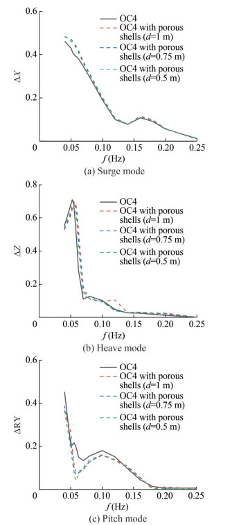 Figure 9 Motion responses of the platform with different wall thicknesses of the porous shells
Figure 9 reveals that changes in the wall thickness of the porous shells have a relatively small effect on the motion response of the platform in the surge DOF. However, a considerable influence in the heave and pitch DOF is observed. An altered peak frequency can be attributed to the effect on the heave DOF. An increase in wall thickness causes a shift of the peak frequency toward high frequencies and a reduction in the peak magnitude. A second peak with wall thickness d = 1 m also emerges around 0.12 Hz frequency due to the change in the applied force area in the heave direction (Figure 10(b)). The influence of the wall thickness on the pitch motion response is mainly restricted to the magnitudes of the motion responses. Within the range of 0.05–0.13 Hz, increasing the wall thickness of the porous shells enhances the suppression of the motion response in pitch DOF.
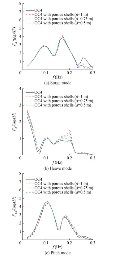 Figure 10 Excitation forces on the platform with different wall thicknesses of porous shells
Figure 10 shows a significant increase in the magnitude of the excitation force of the platform in the heave DOF when the wall thickness of the porous shells increases. This increase in the first-order excitation force corresponds to the second peak in Figure 10(b) at 0.2 Hz. In the pitch DOF, the excitation force on the platform decreases with increasing wall thickness at the low frequency band (f < 1.1 Hz) but increases with the entrance of the frequency to the high frequency range (f > 0.18 Hz). Increasing the wall thickness minimally affects the surge DOF excitation force in the majority of the wave conditions investigated. However, some variation in the surge excitation force is observed in the high-frequency range (f > 0.22 Hz).
Figures 11(a) and (c) show a reduction in surge and pitch added mass, respectively, with the increase in wall thickness. However, the added mass variation in the heave DOF is highly complex. The heave added mass increases with wall thickness in the low frequency region (f < 0.2 Hz) but decreases correspondingly in the high frequency region (f > 1.2 Hz).
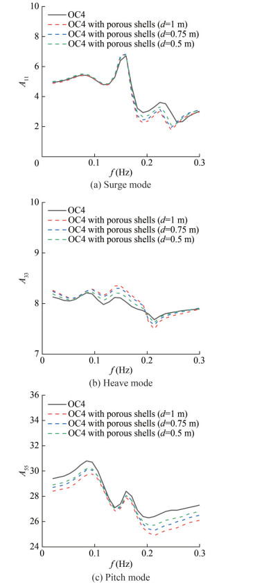 Figure 11 Added mass of the platform with different wall thicknesses of porous shells
Figure 12 shows the relatively small effect of wall thickness variation on the radiation damping in the surge direction, and the influence is mainly observed in the heave and pitch directions. In the heave and pitch DOF and, to a lesser extent, in the surge DOF, increasing the wall thickness of the porous shells can raise the radiation damping.
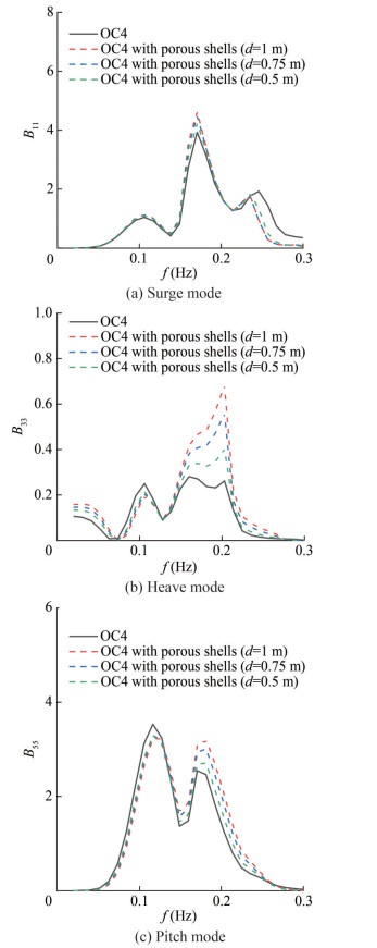 Figure 12 Radiation damping of the platform with different wall thicknesses of porous shells
Figure 13 shows the influence of the radius of the porous shell on the motion responses, where "OC4" and "OC4 with porous shells (D = 20 m)" represent the traditional platform and the platform with a porous shell diameter of 20 m, respectively. The change in the diameter of the porous shells slightly affects the surge and heave DOF motion responses. The influence on the pitch DOF is mainly observed at the value of the second peak. Decreasing the radius of the porous shells raises the magnitude of the second peak. The effects of exciting force, added mass, and radiation damping are not investigated due to the relatively small influence of the radius of the porous shells on the motion response.
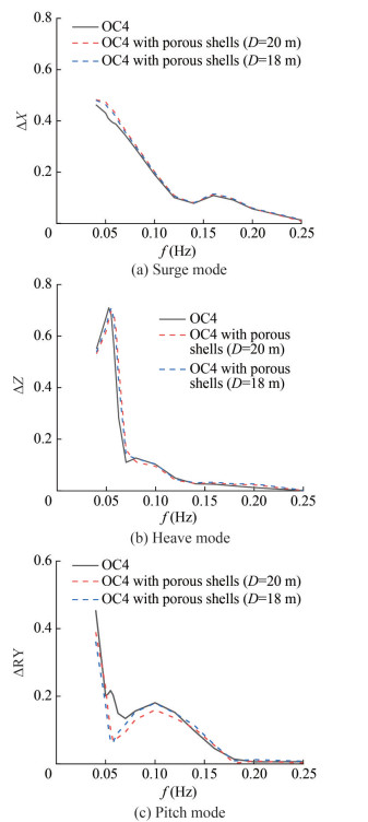 Figure 13 Motion responses of the platform with different radii of porous shells
Figure 14 shows the influence of the porosity of the porous shell on the motion responses, where "OC4" and "OC4 with porous shells (τ = 0.1)" represent the traditional platform and the platform with porous shell porosity of 0.1, respectively.
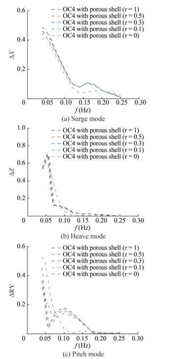 Figure 14 Motion responses of the platform with different porosities
Figure 14(a) reveals the gradual increase in motion response in the surge DOF as the porosity τ decreases. A slight shift in the peak motion response in the surge DOF at the lowest frequency up to 0.05 Hz is observed when the porosity decreases. This shift may be attributed to the reduction in shell porosity to a critical limit, in which the voids in the shell are only slightly effective in influencing the surge motion.
Figure 14(b) displays the effects of varying porosity on the platform motion response in the heave direction. The wave frequency peak initially transitions to a higher frequency as the porosity decreases. This phenomenon is consistent with the effect of porous shells on the motion response in the surge DOF. The reduction of porosity to its lower limit leads to an increased suppression in the heave motion response in the frequency band range of 0.06–0.14 Hz.
Figure 14(c) shows the effects of the shell porosity on the pitch DOF. In the low-frequency region (f < 0.06 Hz), a large porosity enhances the effects of motion response suppression. At 0.06 < f < 0.14 Hz, a small porosity leads to a superior effect of motion response suppression. The combination of the OC4 platform with porous shells with small porosity generally yields a smooth motion response curve.
5 Conclusions
A novel semi-submersible platform, namely the OC4 type platform with porous shells, was introduced in this study to support a 5 MW wind turbine at a water depth of 200 m. A fully coupled analysis using OpenFAST© was performed to obtain the motion response performance of the novel platform. The results obtained from the proposed structure were compared with the motion response of an unmodified OC4-DeepCwind semi-submersible platform to evaluate the effects of the porous shells on the motion response of the platform. In addition to the effects of the geometric parameters of the porous shells, the effects of the porous shells on the first-order exciting force, added mass, and radiation damping were also investigated. The final research results observed in this study are summarized as shown below.
1) Based on the numerical simulation results, the newly designed OC4 platform with porous shells exhibits improved stability. The platform motion is effectively suppressed, especially in the pitch and heave DOFs. A slight increase in the motion response in the surge DOF in the low frequency wave region can be attributed to the porous shells.
2) The geometric parameters of the porous shells have a considerable influence on the hydrodynamic performance of the platform. The amplitude of the motion response of the platform mainly demonstrates the effects of the wall thickness variation. Meanwhile, a change in the porosity affects not only the amplitude of motion but also the resonant period of the platform.
3) The intricate influence of the porous shells on the hydrodynamic coefficients of the platform affects not only the first-order exciting forces but also the radiation damping and added mass coefficients. Moreover, the complexity and variation of wave frequency ranges lead to the different effects of the parameters of porous shells on the hydrodynamic coefficients. Circumstances in which the effect of the porous shell parameters leads to contrasting hydrodynamic responses in the high- and low-frequency regions may also occur.
A novel semi-submersible platform, including comparisons of motion responses and hydrodynamic parameters with a traditional, unmodified platform, is presented in this study. The obtained data revealed the remarkable advantages of integrating the porous shells with the semi-submersible platform. However, this study only conducted a preliminary exploration of the geometric parameter variations for various porous shell components. Subsequent scientific studies will perform a sequential optimization study on the porous shell geometry, and future studies will discuss the viscous effect of porous shells.
Competing interest Dezhi Ning is an editorial board member for the Journal of Marine Science and Application and was not involved in the editorial review, or the decision to publish this article. All authors declare that there are no other competing interests.Open Access This article is licensed under a Creative Commons Attribution 4.0 International License, which permits use, sharing, adaptation, distribution and reproduction in any medium or format, as long as you give appropriate credit to the original author(s) and thesource, provide a link to the Creative Commons licence, and indicateif changes were made. The images or other third party material in thisarticle are included in the article's Creative Commons licence, unlessindicated otherwise in a credit line to the material. If material is notincluded in the article's Creative Commons licence and your intendeduse is not permitted by statutory regulation or exceeds the permitteduse, you will need to obtain permission directly from the copyrightholder. To view a copy of this licence, visit http://creativecommons.org/licenses/by/4.0/. -
Figure 1 Integrated system comprising the OC4-DeepCwind with three porous shells
Figure 2 Mesh convergence analysis and grid distribution schematic
Figure 3 Comparison of the wave forces on the cylinder with different analysis methods
Figure 4 Comparison of added mass and radiation damping with WAMIT
Figure 5 Comparison of excitation forces FX, FZ and moment MRY with WAMIT
Figure 6 Comparison of motion responses in surge, heave, and pitch modes with porous shells
Figure 7 Comparison of excitation forces and moment on the platform with and without porous shells
Figure 8 Comparisons of added mass and radiation damping in different modes with and without porous shells
Figure 9 Motion responses of the platform with different wall thicknesses of the porous shells
Figure 10 Excitation forces on the platform with different wall thicknesses of porous shells
Figure 11 Added mass of the platform with different wall thicknesses of porous shells
Figure 12 Radiation damping of the platform with different wall thicknesses of porous shells
Figure 13 Motion responses of the platform with different radii of porous shells
Figure 14 Motion responses of the platform with different porosities
Table 1 Traditional platform dimensions (Benitz et al., 2014)
m Depth of platform base below still water line 20 Centerline spacing between offset columns 50 Length of upper columns 26 Length of base columns 6 Diameter of main columns 6.5 Diameter of offset columns 12 Diameter of base columns 24 Diameter of pontoons and cross braces 1.6 Table 2 Novel porous shell integrated platform dimensions
Hull diameter Dp (m) 12 Heave plate diameter DH (m) 24 Center column diameter Dpm (m) 6.5 Bracing diameter Dd (m) 1.6 Total platform height Hp (m) 32 Operating draft hd (m) 19.36 Height of damping plate BP (m) 6 Displacement (kg) 1.347 3×10⁷ Table 3 Porous shell dimensions
Porosity τ 0.3 Outer diameter Dout (m) 20 Wall thickness d (m) 0.5 Total height H (m) 6 Operating draft h (m) 4 -
ANSYS AQWA (2016) AQWA user's manual release 17.0. ANSYS Inc., Canonsburg, USA, 3-64 Benitz MA, Schmidt DP, Lackner MA, Ste M (2014) Comparison of hydrodynamic load predictions between reduced order engineering models and computational fluid dynamics for the OC4-DeepCwind semi-submersible. Proceedings of the ASME 2014 33rd International Conference on Ocean, Offshore and Arctic Engineering, Volume 9B: Ocean Renewable Energy, San Francisco, USA, P1. DOI: 10.1115/OMAE2014-23985 Cutler J, Bashir M, Yang Y, Wang J, Loughney S (2022) Preliminary development of a novel catamaran floating offshore wind turbine platform and assessment of dynamic behaviours for intermediate water depth application. Ocean Engineering 258: 111769. DOI: 10.1016/j.oceaneng.2022.111769 Coulling AJ, Goupee AJ, Robertson AN, Jonkman JM, Dagher HJ (2013) Validation of a FAST semi-submersible floating wind turbine numerical model with DeepCwind test data. Journal of Renewable & Sustainable Energy 5(2): 557-569. DOI: 10.1063/1.4796197 Ding Q, Li C, Yuan W, Hao W (2019) Effects of heave plate on dynamic response of floating wind turbine spar platform under the coupling effects of wind and wave. Zhongguo Dianji Gongcheng Xuebao/Proceedings of the Chinese Society of Electrical Engineering 39(4): 1113-1126. DOI: 10.13334/j.0258-8013 Edwards EC, Holcombe A, Brown S, Ransley E, Hann M, Greaves D (2023) Evolution of floating offshore wind platforms: A review of at-sea devices. Renewable & Sustainable Energy Reviews 183: 113416. DOI: 10.1016/j.rser.2023.113416 Faltinsen O (1990) Sea loads on ships and offshore structure. Cambridge University Press, New York, 34-106 Gaudiosi G (1994) Offshore wind energy in the Mediterranean and other European Seas. Renewable Energy 5(1): 675-691. DOI: 10.1016/0960-1481(94)90453-7 Gaudiosi G (1996) Offshore wind energy in the world context. Renewable Energy 9(1): 899-904. DOI: 10.1016/0960-1481(96)88425-4 GWEC (2023) Global offshorewind report 2023. Global Wind Energy Council, Brussels, Belgium. Available from http://www.gwec.net/global-figures/global-offshore/ [Accessed on March. 23, 2024] Hall M (2015) MoorDyn user's guide. Department of Mechanical Engineering, University of Maine, Orono, USA, 15 Jiang Z, Wen B, Chen G, Xiao L, Li J, Peng ZK, Tian X (2021) Feasibility studies of a novel spar-type floating wind turbine for moderate water depths: Hydrodynamic perspective with model test. Ocean Engineering 233: 109070. DOI: 10.1016/j.oceaneng.2021.109070 Jonkman J (2007) Dynamics modeling and loads analysis of an offshore floating wind turbine. PhD thesis, University of Colorado Boulder, Boulder, USA, 27-64 Jonkman J (2020) OpenFAST documentation-Release 2.4.0. National Renewable Energy Laboratory, USA, 1-435 Jonkman J, Buhl M (2007) Development and verification of a fully coupled simulator for offshore wind turbines. 45th AIAA Aerospace Sciences Meeting, 212 Liu Y, Li S, Yi Q, Chen D (2016) Developments in semi-submersible floating foundations supporting wind turbines: A comprehensive review. Renewable & Sustainable Energy Reviews 60: 433-449. DOI: 10.1016/j.rser.2016.01.109 Loughney S, Wang J, Bashir M, Armin M, Yang Y (2021) Development and application of a multiple-attribute decision-analysis methodology for site selection of floating offshore wind farms on the UK Continental Shelf. Sustainable Energy Technologies and Assessments 47: 101440. DOI: 10.1016/j.seta.2021.101440 Mackay E, Shi W, Qiao D, Gabl R, Davey T, Ning D, Johanning L (2021) Numerical and experimental modelling of wave interaction with fixed and floating porous cylinders. Ocean Engineering 242: 110118. DOI: 10.1016/j.oceaneng.2021.110118 Moriarty PJ, Hansen AC (2005) AeroDyn theory manual. National Renewable Energy Lab., Golden, CO, USA, No. NREL/TP-500-36881 Nielsen FG, Hansen TD, Skaare B (2006) Integrated dynamic analysis of floating offshore wind turbines. Proceedings of the ASME 2006 25th International Conference on Ocean, Offshore and Artic Engineering, 671-679. DOI: 10.1115/OMAE2006-92291 Ning A, Hayman G, Damiani R (2015) Development and validation of a new blade element momentum skewed-wake model within AeroDyn. 33rd Wind Energy Symposium, AIAA 2015-0215. DOI: 10.2514/6.2015-0215 Soeb M, Islam A, Jumaat M, Huda N, Arzu F (2017) Response of nonlinear offshore spar platform under wave and current. Ocean Engineering 144: 296-304. DOI: 10.1016/j.oceaneng.2017.07.042 Uzunoglu E, Guedes Soares C (2020) Hydrodynamic design of a free-float capable tension leg platform for a 10 MW wind turbine. Ocean Engineering 197: 106888. DOI: 10.1016/j.oceaneng.2019.106888 Vaezi M, Pourzangbar A, Fadavi M, Mousavi SM, Sabbahfar P, Brocchini M (2021) Effects of stiffness and configuration of brace-viscous damper systems on the response mitigation of offshore jacket platforms. Applied Ocean Research 107: 102482. DOI: 10.1016/j.apor.2020.102482 Wang J, Qin S, Jin S, Wu J (2015) Estimation methods review and analysis of offshore extreme wind speeds and wind energy resources. Renewable & Sustainable Energy Reviews 42: 26-42. DOI: 10.1016/j.rser.2014.09.042 Yang Y, Bashir M, Michailides C, Li C, Wang J (2020) Development and application of an aero-hydro-servo-elastic coupling framework for analysis of floating offshore wind turbines. Renewable Energy 161: 606-625. DOI: 10.1016/j.renene.2020.07.134 Yao Y, Ning D, Deng S, Mayon R, Qin M (2023) Hydrodynamic investigation on floating offshore wind turbine platform integrated with porous shell. Energies 16(11): 4376. DOI: 10.3390/en16114376 Yu M, Hu Z, Xiao L (2015) Wind-wave induced dynamic response analysis for motions and mooring loads of a spar-type offshore floating wind turbine. Journal of Hydrodynamics 26(6): 865-874. DOI: 10.1016/S1001-6058(14)60095-0 Zhang L, Michailides C, Wang Y, Shi W (2020a) Moderate water depth effects on the response of a floating wind turbine. Structures 28: 1435-1448. DOI: 10.1016/j.istruc.2020.09.067 Zhang L, Shi W, Karimirad M, Michailides C, Jiang Z (2020b) Second-order hydrodynamic effects on the response of three semisubmersible floating offshore wind turbines. Ocean Engineering 207(C): 107371. DOI: 10.1016/j.oceaneng.2020.107371 Zhao Z, Shi W, Wang W, Qi S, Li X (2021) Dynamic analysis of a novel semi-submersible platform for a 10 MW wind turbine in intermediate water depth. Ocean Engineering 237: 109688. DOI: 10.1016/j.oceaneng.2021.109688 Zhao Y, Yang J, Gu M (2016) Coupled dynamic response analysis of a multi-column tension-leg-type floating wind turbine under combined wind and wave loading. Jouranl of Shanghai Jiaotong University (Science) 21(1): 103-111. DOI: 10.1007/s12204-015-1689-5 Zhou Y, Xiao Q, Peyrard C, Pan G (2021) Assessing focused wave applicability on a coupled aero-hydro-mooring FOWT system using CFD approach. Ocean Engineering 240: 109987. DOI: 10.1016/j.oceaneng.2021.109987 Zou Q, Lu Z, Shen Y (2023) Short-term prediction of hydrodynamic response of a novel semi-submersible FOWT platform under wind, current and wave loads. Ocean Engineering 278: 114471. DOI: 10.1016/j.oceaneng.2023.114471
