
Effect of Cracked and Notched Stiffeners on the Ultimate Strength of Steel Stiffened Panels
https://doi.org/10.1007/s11804-024-00417-2
-
Abstract
This paper numerically evaluates the effect of the crack position on the ultimate strength of stiffened panels. Imperfections such as notches and cracks in aged marine stiffened panels can reduce their ultimate strength. To investigate the effect of crack length and position, a series of nonlinear finite element analyses were carried out and two cases were considered, i. e., case 1 with thin stiffeners and case 2 with thick stiffeners. In both cases, the stiffeners have the same cross-section area. To have a basis for comparison, the intact panels were modeled as well. The cracks and notches were in the longitudinal and transverse direction and were assumed to be in the middle part of the panel. The cracks and notches were assumed to be through the thickness and there is neither crack propagation nor contact between crack faces. Based on the numerical results, longitudinal cracks affect the behavior of the stiffened panels in the postbuckling region. When the stiffeners are thinner, they buckle first and provide no reserved strength after plate buckling. Thus, cracks in the stiffeners do not affect the ultimate strength in the case of the thinner stiffeners. Generally, when stiffeners are thicker, they affect the postbuckling behavior more. In that case, cracks in the stiffeners affect the buckling and failure modes of the stiffened panels. The effect of notch was also studied. In contrast to the longitudinal crack in stiffeners, a notch in the stiffeners reduces the ultimate strength of the stiffened panel for both slender and thick stiffeners.-
Keywords:
- Stiffened panels ·
- Crack ·
- Notch ·
- Ultimate strength ·
- Buckling ·
- Nonlinear finite element method
Article Highlights● The effect of a cracked stiffener on the ultimate strength of stiffened panels is investigated numerically.● The ultimate strength and failure modes of notched stiffened panels are studied using the finite element method.● The impact of crack location, notch depth, and crack length on the ultimate strength and buckling modes are analyzed. -
1 Introduction
Plates and stiffened panels are the principal parts of marine structures, and they are subjected to various severe loads. One of which is the in-plane loads from hull girder bending stresses. To investigate the effect of these forces, ship structural designers face many challenges. On one hand, nowadays, due to new manufacturing methods and higher-strength materials, the structures are becoming thinner and more prone to buckling and consequently, the structural design processes emphasize more on buckling and compressive behavior of the structures. (Ikeda and Morota, 2022) On the other hand, marine structures are exposed to harsh environments, which may cause corrosion, cracks, and other imperfections. In marine applications, improper design, structural defects, or repetitive loading can cause cracks in stiffened plates. These cracks can reduce their ultimate strength and safety factor. The decrease in the ultimate strength of marine structures causes danger to human lives.
Considering the importance of the ultimate strength of stiffened plates, many researchers have studied the ultimate strength of steel and aluminum stiffened plates. Experiments to understand the compressive behavior of stiffened panels are scarce, i.e., Aalberg et al. (2001), Ghavami and Khedmati (2006) and Xu and Soares (2012) conducted a series of experiments to investigate the effect of different parameters on the ultimate strength of stiffened panels.
Kim et al. (2009) and Liu et al. (2020) numerically investigated the ultimate strength of long-span stiffened and perforated panels, respectively, and concluded that the design formula for critical buckling strength in both cases is applicable. Ozdemir et al. (2018) and Zhang and Khan (2009) also re-evaluated the existing formula for designing contemporary large ships by using the nonlinear finite element method and proposed some other empirical formulas in that field. Putranto et al. (2021) suggested an equivalent single-layer plate theory to calculate the ultimate strength and compressive behavior of stiffened panels and model local and global buckling behavior.
Many parameters can affect the ultimate strength of stiffened panels under inplane loads. Anyfantis (2020), Hosseinabadi et al. (2021), and Li et al. (2021) studied the influence of residual stress, load distribution, and initial imperfection on the ultimate strength of stiffened panels, respectively. Song et al. (2019) investigated the effect of the test scale on the failure modes of the stiffened panels. They reported that the plate slenderness, the stiffener slenderness and the torsional stiffness are more important than test scales. Khedmati et al. (2009) investigated the effect of construction methods and showed that the ultimate strength of continuously fillet welded stiffened panels is less than the ultimate strength of staggered intermittent fillet welded stiffened panels.
Like intact stiffened panels, there are two approaches adopted to investigate the effects of the cracks on the ultimate strength of the stiffened panels. One is to test a stiffened panel under compressive load; the other is to model the cracked stiffened panel using a nonlinear finite element. To date, several studies have investigated the strength of intact stiffened panels. Thin-walled structures are prone to buckling and their ultimate strength under compressive loads is less than their ultimate strength under tensile loads. Consequently, in many studies, the strength of the stiffened panels has been investigated under compressive loads. While, for cracked panels under tension, the compressive stress field near a crack or a hole can cause local instability. In this regard, Brighenti (2005) and Shaw and Huang (1990) studied the effect of centered cracks and holes on the local buckling of the plates under tension. Although cracked plates may buckle locally under tensile load, it is more probable that they buckle under compressive loads. Babazadeh and Khedmati (2019), Cui et al. (2016, 2017), Khedmati et al. (2009), Paik et al. (2008, 2009), and Xia et al. (2018) investigated cracked stiffened panel ultimate and studied the failure mode changes and strength reduction due to the existence of the cracks in the plating. Bayatfar et al. (2014) and Margaritis and Toulios (2012) studied the effect of transverse crack, either on the plating or in the plating and the base of the stiffeners. In addition, some researchers have investigated the effect of the crack orientation and length on the strength of the stiffened panel. (Han et al. (2021), Khedmati et al. (2010), Shi et al. (2017), Xu and Soares (2012), Yu et al. (2018), and Zhang et al. (2022))
The concept of the ultimate strength of stiffened panels with cracks in the plating is studied to the full extent, while studies on the effect of cracks in the stiffeners on the ultimate strength are limited. Moreover, the compressive strength and bucking modes of stiffened panels mainly depend on the stiffeners' features, and the stiffeners' imperfections and defects will directly affect the ultimate strength of stiffened panels. Thus, it is of great importance to understand the effects of imperfections such as cracks and notches on the ultimate strength of stiffened panels. In the present study, a comparison of the ultimate strength of intact stiffened panels and the panels with various cracks and notches under uniaxial compression by using nonlinear elasto-plastic large deflection is investigated.
2 Nonlinear finite element model
2.1 Model description
To study the effect of crack position on the compressive behavior of cracked stiffened plates, two cases of stiffened plates with different stiffeners' slenderness ratios are modeled using the nonlinear finite element method. In both cases, the cross-section area of the stiffeners is the same. In this paper, the notch and crack terminology are used to describe the crack on the edge of the stiffener (named as N specimens-Figure 1) and the crack in the plating and stiffeners (named as C specimens-Figure 1), respectively. Notch length is defined in the z direction which is along the depth direction of stiffeners, while the crack length is defined in the longitudinal direction.
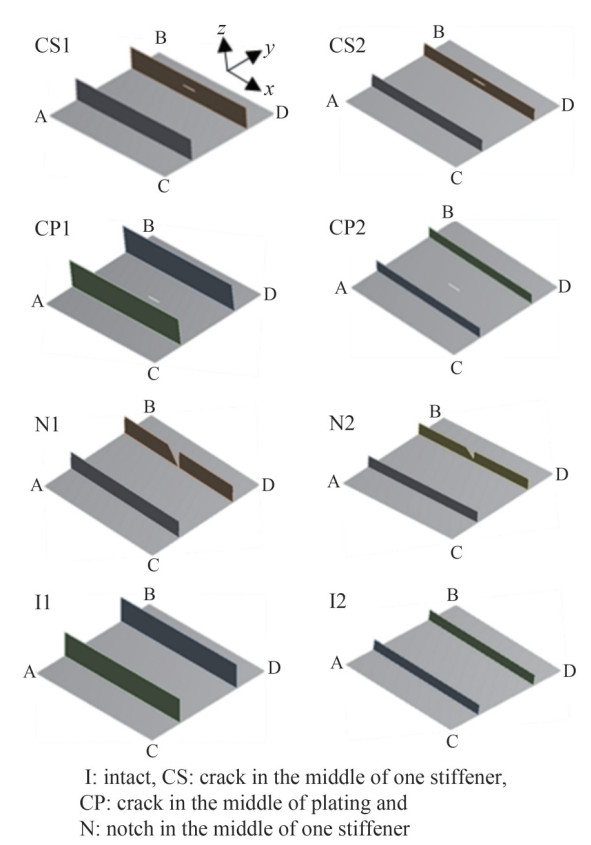 Figure 1 The studied cracked and notched stiffened panels
These cases consist of a 300 mm×300 mm plate of 2 mm thickness stiffened with 60 mm×2 mm (Case 1) and 30 mm× 4 mm (Case 2) flat bars. The extent of the model is limited to a (1/2+1+1/2) bay stiffened panel model based on Xu and Soares (2012) who recommended that a (1/2+1+1/2) bay model of stiffened panels is more stable than a (1+1) bay model in testing.
For both cases, an intact stiffened panel (I), a series of cracked stiffened panels with a crack in the plating (CP) or a crack in one stiffener (CS), and a series of notched stiffened panels with a notch in one stiffener are considered. The models are named based on the cracks and notches positions and the stiffened panel cases, i.e., CS1 is the cracked stiffened panel case 1 in which the crack is positioned in one of the stiffeners. In all cases, the cracks and notches are assumed to be in the middle of the plating or the middle of one of the stiffeners (Figure 1).
In calculating the ultimate strength of the stiffened panels, the loading is monotonic. Many researchers have investigated the ultimate strength of cracked stiffened panels.
Crack initiation and growth depend on the loading conditions and the joint details. Since transverse welding is used to connect the longitudinal stiffeners in ships, there is a possibility of crack growth in the middle of the stiffeners. Babazadeh and Khedmati (2018) reviewed the literature and concluded that "crack propagation is generally ignored by most researchers". In this study, the cracks are assumed to be locked with round tips, thus the crack propagation is ignored. The effect of the crack's position and the crack's length on the ultimate strength of the stiffened panels are investigated. i. e., the effect of cracks and notches lengths of 10 mm, 20 mm, and 30 mm are studied. The crack gap is considered to be 2 mm.
The stiffened panels are made of mild steel, which is common in shipbuilding industries. The material properties have been specified as Young's modulus, E=200 GPa, the Poison's ratio ν =0.3, and the yielding stress σy=200 MPa by Xu and Soares (2012).
2.2 Initial imperfection
Initial imperfections have significant effects on the ultimate strength, and buckling behavior of stiffened panels. Due to the uncertainties during manufacturing stiffened panels, its initial imperfection is very complex; yet it can be described by a double sinusoidal series, (Fujikubo et al., 2005a; Fujikubo et al., 2005b):
$$ W_0=\sum\limits_{m=1}^{\infty} \sum\limits_{n=1}^{\infty} A_{0 m n} \sin \frac{m {\rm{\mathsf{π}}} x}{a} \sin \frac{n {\rm{\mathsf{π}}} y}{b} $$ (1) In this case, only the first term (n=1) may roll a play, and simple form of initial imperfection is expressed in below:
$$ W_0=\sum\limits_{m=1}^{\infty} A_{0 m 1} \sin \frac{m {\rm{\mathsf{π}}} x}{a} \sin \frac{{\rm{\mathsf{π}}} y}{b} $$ (2) Many researchers have used this deformation formulation to describe the initial deformation in stiffened panels (Ueda & Yao, 1985) (Khedmati et al., 2012). (Yao et al., 1992) introduced A0m1 terms up to m = 11 for the so-called "idealized thin-horse mode" (Table 1).
Table 1 Coefficients of thin-horse mode initial deflection (Yao et al., 1992)a/b 1 2 3 $1 <a/b<\sqrt{2}$ $\sqrt{2} <a/b<\sqrt{6}$ $\sqrt{6} <a/b<\sqrt{12}$ W01/t 1.115 8 1.142 1 1.145 8 W02/t −0.027 6 −0.045 7 −0.061 6 W03/t 0.137 7 0.228 4 0.307 9 W04/t 0.002 5 0.006 5 0.022 9 W05/t −0.012 3 0.032 6 0.114 6 W06/t −0.000 9 −0.002 2 −0.006 5 W07/t −0.004 3 −0.010 9 0.032 7 W08/t 0.000 8 0.001 0.000 W09/t 0.003 9 −0.004 9 0.000 W10/t −0.000 2 −0.000 5 −0.001 5 W11/t −0.001 1 0.002 7 −0.007 4 In this research, the initial imperfection is applied to all cases using equation (2) and the compressive behavior of the imperfect and perfect stiffened panels are compared.
2.3 Loading and boundary conditions
To model the stiffened panels' behaviors, it is important to employ proper boundary conditions. The ultimate strength of marine stiffened panels is evaluated under axial in-plane compression loading. The boundary conditions to model this loading were described by Cui et al. (2016), who used a displacement-controlled loading to model the compressive behavior of the stiffened panels. The uniaxial compressive loading can be described as follows, in which Lines AB, CD, AC, and BD are shown in Figure 1.
⋅ Line AB: the displacement in all directions (x, y, z) are constrained.
⋅ Line CD: the displacement of 4 mm is applied in the x-direction, and the displacement in the other directions is considered zero.
⋅Lines AC and BD: free to move.
3 Element size sensitivity analysis
In the finite element method, the element size will determine the calculation accuracy. On one hand, the element size should be small enough to properly describe the behavior of the structure. On the other hand, small elements can increase the calculation time dramatically. The element sizes have been chosen based on the element size sensitivity analysis and 118 elements in the longitudinal direction and 56 elements in the depth direction of the plate are used to mesh the plates. In stiffeners, for case 1 and case 2, there are 11 elements and 5 elements in the depth direction, respectively. All the models are constructed of thin plates. Thus, due to the small plate thickness to the plate dimension ratio, the models are meshed using shell elements.
In the numerical model of cracked structures, the crack tips' stress depends on the mesh size in the vicinity of the crack tips (Shi et al., 2017). To determine the size of the crack tips' elements, the CS2 case with a crack of 10 mm is considered. In this case, the crack tips are divided into Ne meshes, and the effect of the crack tips' element size is determined by obtaining the ultimate strength σu and the crack tips' maximum stress σmax. The crack tips' maximum stress to yield stress ratio and the ultimate strength to yield stress ratio versus Ne are presented in Figure 2. Figure 3, also, illustrates the plastic strain distribution for various Ne at the point of ultimate strength. It can be deduced, from both figures, that for Ne bigger than 16, the accuracy of the solution did not increase. Thus, the number of the crack tips element equal to 16 is used in the analysis of this research.
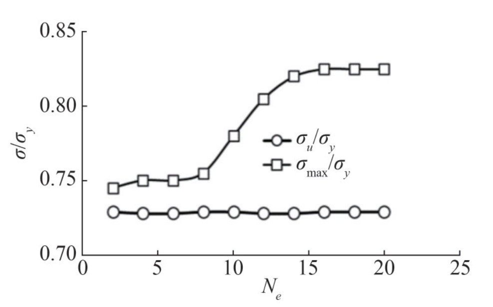 Figure 2 Mesh size sensitivity analysis (Ne: Number of the elements at the crack tips)
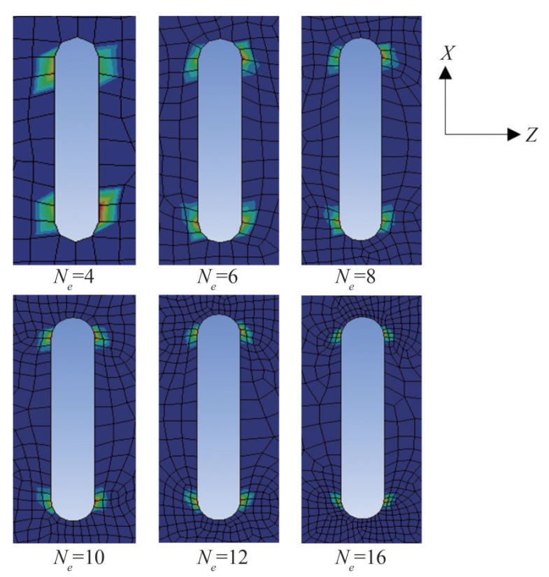 Figure 3 Plastic strain distribution near the crack tips at the ultimate limit state for CS2 and De=10 mm with various Ne (Number of the element at the crack tips)
4 Verification of numerically model
To verify the numerical model, the results are compared to the results of the Shi et al. (2017) study. They conducted a series of tests and numerical modelling to evaluate the ultimate strength and buckling behavior of cracked stiffened panels. They assumed that a through thickness crack is positioned on the center of the plate and there is no crack propagation.
In the present study, the axial loading -displacement curve for a model from the Shi et al. (2017) study is extracted using numerical method. Figure 4 illustrates the force-displacement diagram deriving from the presented numerical method and Shi et al. (2017) results. It can be deduced that the present method is accurate for analyzing the effect of the cracks and notches.
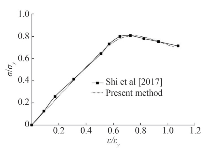 Figure 4 Normalized average stress-normalized average strain obtained by the present method and the Shi et al. (2017) study
5 Results and discussion
In this paper, a series of nonlinear finite element analyses were carried out to study the compressive behavior of cracked and notched stiffened panels under uniaxial in-plane compression. The effect of crack position, crack length and the effect of the notched stiffener on the ultimate strength of the stiffened panels were studied. To evaluate the effect of crack position, two different stiffened panels, and 2 crack scenarios, as defined in Figure 1, are studied, i. e. CP1, CP2, CS1, and CS2 (Figure 1). To have a basis for comparison two intact cases, I1 and I2 are also considered. In the above-mentioned cases, the crack length effect on the ultimate strength was also studied. Then the effect of the notches on the stiffeners' edge on the ultimate strength of stiffened panels is investigated.
5.1 Effect of initial imperfection
The average stress -average strain curves for perfect and imperfect cases are shown in Figure 5 and the deformation of these cases at the ultimate strength is shown in Figure 6. Initial imperfection can affect the compressive behavior of the stiffened panels. Solid lines indicate perfect cases and dashed lines indicate imperfect cases. At first, when the applied force is low, the initial stiffness of the samples decreases due to the initial deformation. It can be seen in the change of the initial slope of the curves. The initial imperfection decreases the first the buckling load of the stiffened panels. For example, the perfect I1 panel first buckles at Point A, while the imperfect I1 panel first buckle in Point C. And, the perfect I2 panel first buckles at Point E, while the imperfect I2 panel buckles at Point G. The ultimate strength of the both perfect and imperfect of both cases achieved by the failure of the same structural member; however, the initial imperfection may guide the failure mode shape to be different. The summary of the failure modes of perfect and imperfect stiffened panels are shown in Tables 2 and 3.
Table 2 The summary of the failure modes of the perfect stiffened panelsCase Average stress (MPa) Structural member failure No. of buckling mode half-waves Point in Figure 5 I1 93.8 Side plate buckling 1 A 145.8 Web plate buckling (ultimate strength) 1 B 145.8 Center plate buckling (ultimate strength) 1 B I2 142.7 Side plate buckling 2 E 169.9 Stiffener buckling (ultimate strength) 1 F Table 3 The summary of the failure modes of the imperfect stiffened panelsCase Average stress (MPa) Structural member failure No. of buckling mode half-waves Point in Figure 5 I1 57.7 Side plate buckling 2 C 139.7 Web plate buckling (ultimate strength) 2 D 139.7 Center plate Buckling (ultimate strength) 3 D I2 72.9 Side plating buckling 2 G 76.7 Center plate buckling 3 H 167.5 Stiffener buckling (ultimate strength) 2 H 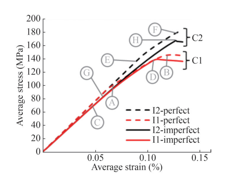 Figure 5 Average stress-average strain diagram of I1, I2 perfect and imperfect stiffened panels.
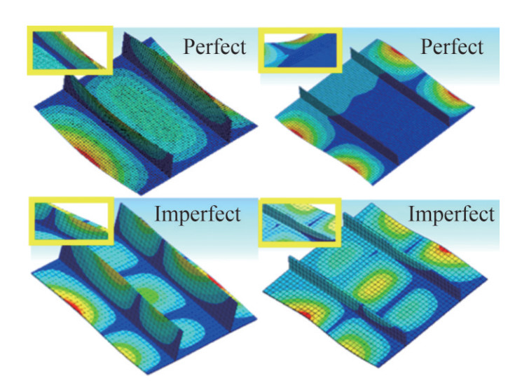 Figure 6 The deformation at ultimate strength for the I1 (perfect), I1 (imperfect), I2 (perfect), and I2 (imperfect)
5.2 Crack in plating
In this section, the effect of a crack in the plating of the stiffened panel is investigated. The average stress-average strain for I1 and I2, and CP1 and CP2 with the crack length of 10 mm, 20 mm, and 30 mm are extracted using the nonlinear finite element method and are shown in Figure 7. The average stress average strain curves are derived from the axial load-end shortening curves. The average stress σavg is the axial load divided by the total cross-section area of the stiffened panels and the average strain εavg is the end shortening divided by the total length of the panel.
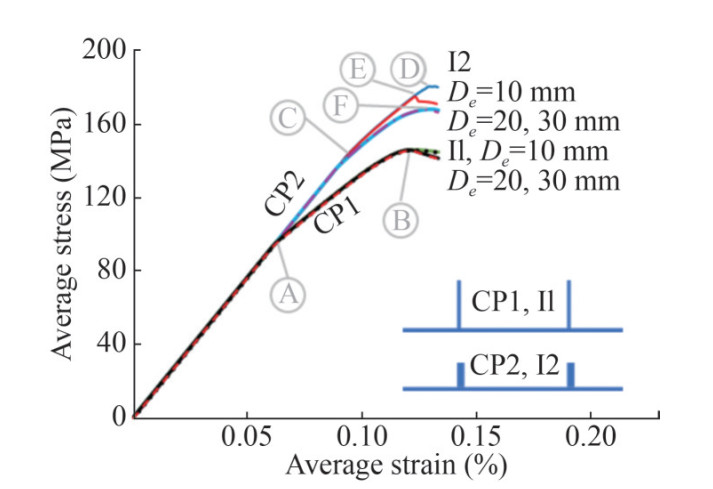 Figure 7 Average stress-average strain diagram of I1, I2, CP1, CP2 with various crack length (De)
Stiffened panels are usually categorized in the thin-walled structures group which are more prone to buckle under compressive loads. For CP1 and CP2 cases, before buckling, the initial stiffness is the slope of average stress-average strain curves in the linear elastic region. In all studied scenarios, the cracks are in the longitudinal directions and they do not reduce the cross-section area of the stiffened panel in the linear elastic region. Thus, in the initial part of the average stress-average strain curves, the initial stiffness of the panels is the same, regardless of the crack position and length.
For stiffened panels under compressive loads, stiffeners may buckle in the lateral, torsional or Euler mode, and the plating may buckle in one or more half-wave mode shape. In the intact form of case 1 (I1), first, side plate is buckled, and the stiffeners' web is buckled closely to the concurrent, and then plate center is buckled in one half wave shape in between stiffeners. Therefore, the slope of the average stress-average strain curve for all Case 1 stiffened panels decreases after stiffeners buckling at Point A in Figure 7. By increasing the loads, the stiffened panel will get to its ultimate strength at Point B. It can be deduced from Figures 7 and 8 that the cracked stiffened panels in CP1 case have almost the same behavior under compressive loads for all crack lengths.
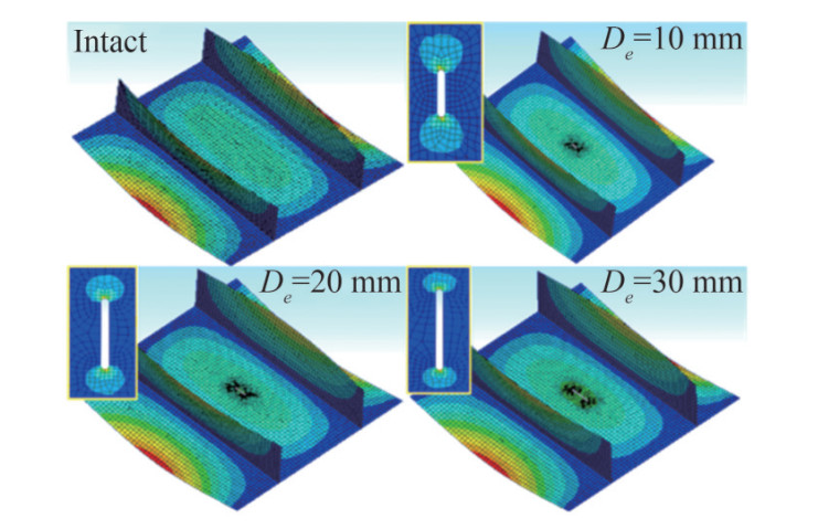 Figure 8 The deformation at ultimate strength for the I1, and CP1 with various crack length (De)
For the I2 case, first, the plating buckled at Point C of Figure 7 in a two-half-waves sinusoidal shape (Figure 9). Then, as the compressive load increased, the load is transferred to the stiffeners until the stiffeners buckled and the ultimate strength of the stiffened panels occurred. For the intact stiffened panel and stiffened panel with the cracked plating with a crack length of 10 mm (De=10 mm), buckling occurs at Point D and Point E, respectively. A crack of length of 10 mm does not affect the behavior of the stiffened panels until the plate of the cracked panel buckles at Point E. For the CP2 cases with De= 20 mm and De= 30 mm the compressive behavior is exactly the same. For larger crack lengths the stiffened panels' ultimate strength does not change.
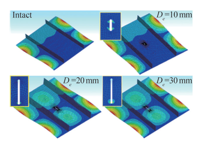 Figure 9 The deformation at ultimate strength for the I2, and CP2 various crack length (De)
5.3 Crack in one stiffener
To study the effect of the crack position on the cracked stiffened panels' ultimate strength, the next step is to study the behavior of the stiffened panel with a cracked stiffener. Figure 10 shows the average stress-average strain for the I1, I2, CS1 and CS2. For CS1 cases, the crack in the stiffener does not change the compressive behavior of the stiffened panel, until the ultimate strength point, B. It means that the stiffeners buckle laterally at point A and get to the ultimate strength at Point B, regardless of the existence of the crack or the crack length. Figure 11 shows no difference between the deformation pattern of I1 and CS1 with various crack lengths.
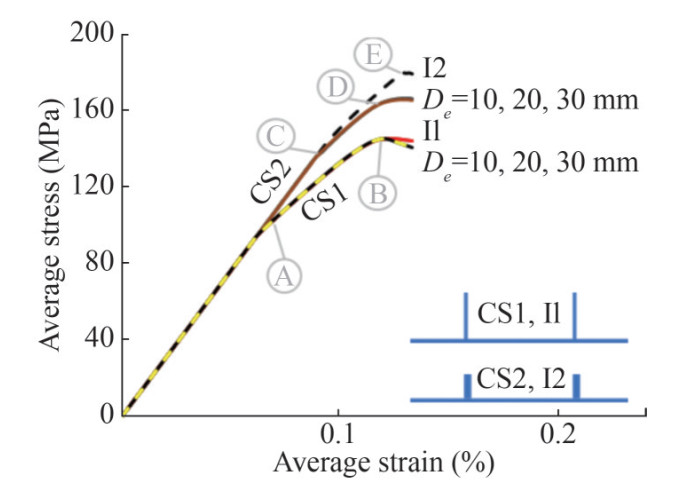 Figure 10 Average stress-average strain diagram of I1, I2, CS1, CS2 with various crack length (De)
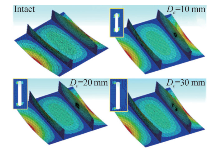 Figure 11 The deformation at ultimate strength for the I1, and CS1 with various crack length
For CS2, in which stiffeners are thicker, the stiffeners play an important role in withstanding internal forces in the post-buckling region. Thus, the behavior of the panel before local plating buckling (Point C) is the same, while for cracked stiffened panels in CS2, the stiffeners buckle at Point D instead of Point E. However, the results of this study show that the crack length, in CS2, does not have any effect on the ultimate strength of the stiffened panels. Consequently, it was observed that, in this group, the intact stiffened panel's buckling mode is different from those of cracked panels. In the intact stiffened panel, the edge plates buckle, while in the cracked stiffened panel, all plates buckle simultaneously. (Figure 12)
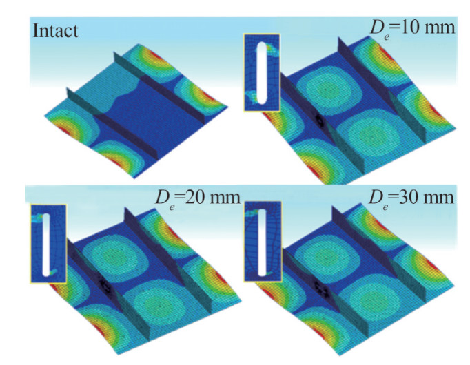 Figure 12 The deformation at ultimate strength for the I2, and CS2 with various crack length
Figure 13 and 14 summarized the results of 5.2 and 5.3 by showing the ultimate strength of all studied cases and scenarios. It shows that crack reduces the load-carrying capacity in CP2 and CS2. For perfect panels, the length (De) does not change the ultimate strength of the stiffened panel after a certain crack length. In all the stiffened panels of case study 1, the plates and the stiffeners buckled at the same load in global buckling mode (Figure 11) and the stiffeners are not effective after buckling. Moreover, due to the crack orientation, its effect is more obvious in the post-buckling region. While the stiffeners are not effective in the post-buckling region. On the other hand, in CS2, the stiffeners stay effective after plate buckling. Therefore. Any defect and imperfection in these stiffeners can decrease the strength of the panels. On the other hand, for imperfect stiffened panels, the crack length slightly changes the strength and the ultimate strength.
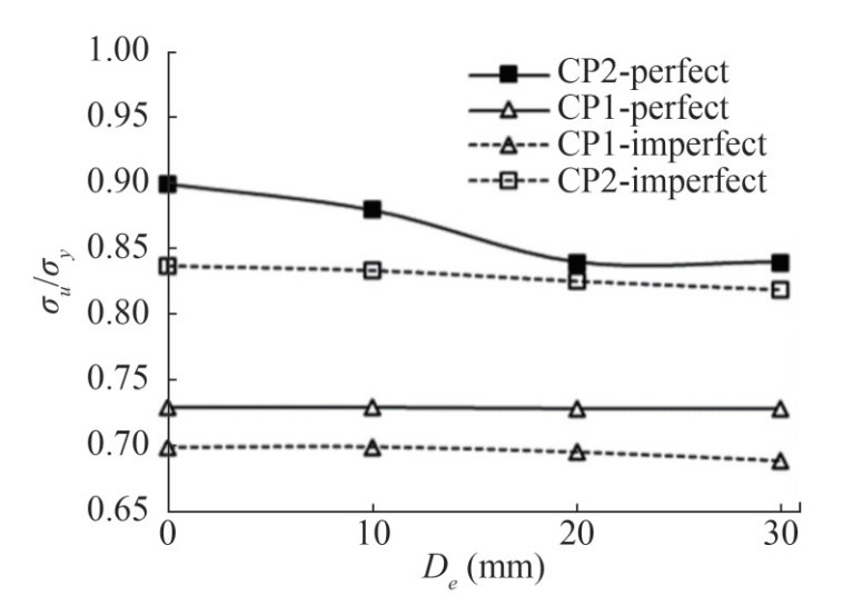 Figure 13 Ultimate strength vs. crack length when crack is placed in the plating
 Figure 14 Ultimate strength vs. crack length when crack is placed in the stiffener
5.4 Notch in one stiffener
Given the focus of this research, in this section, the effect of notches on the edge of stiffeners on the compressive behavior of stiffened panels is studied. The studied cases and scenarios are N1 and N2 (Figure 1). The studied notch lengths are De = 10, 20 and 30 mm.
For the stiffened panels of case 1, the stiffeners buckle laterally first and the plating deform accordingly. When stiffeners buckle, they provide fewer supports for plating. (Figure 15) As stiffeners are less effective after buckling, they have less effect on the ultimate strength and their imperfection and defect also will affect the behavior of the stiffened panels less. Therefore, in case 1, the ultimate strength of the stiffened panel with one notched stiffener (N1) decreases a little and the failure process is the same as the intact stiffened panel (I1).
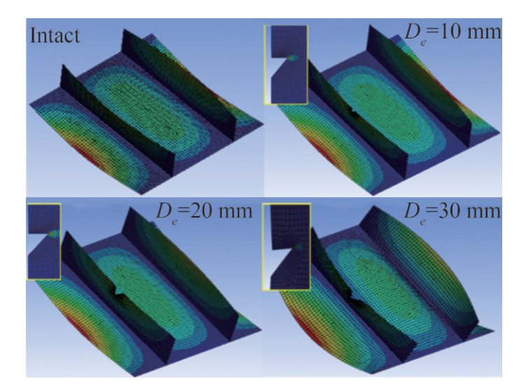 Figure 15 The deformation at ultimate strength of I1 and N1 with various notch depth
Therefore, here, only the average stress-average strain for Case 2 (I2 and N2) is presented in Figure 16. The plastic strain and total deformation of (I2) and (N2) are also shown in Figure 16. In intact form of the case 2, the plating buckle first, at point C. (Also described in Figure 10). In the N2 case when De = 10 and 20 mm, the plating also buckles first. But, in notched cases, as the stiffeners are less effective, the boundary rigidity of the plating is reduced and thus the plating buckles sooner at point A.
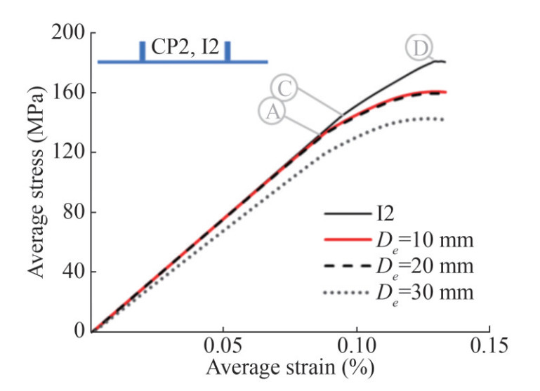 Figure 16 Average stress-average strain diagram of (I1) and N2 cases
The deformation strain of the I1, N1 and N2 is shown in Figures 17. It is obvious that in C1 the deformation modes are unchanged, while in C2, the mode shapes are changed. When the length of the notch is 30 mm the stiffeners are not effective. The reason is the loss of the cross-section of the stiffener.
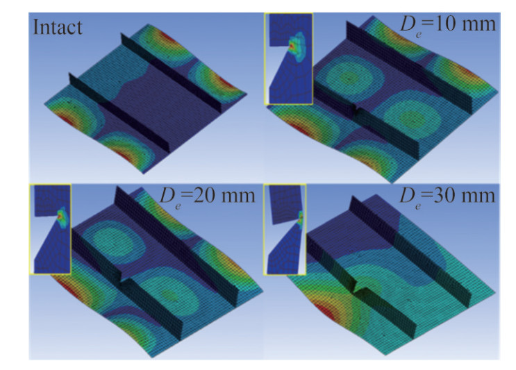 Figure 17 The deformation of I2 and (N2) with various notch depth
Figure 17 shows the ultimate strength of the I1, I2, N1 and N2 vs. the crack length. It can be deduced that the notch length reduces the ultimate strength of the stiffened panels of both cases. The depth of the notch is defined as De. The result is shown, that when the notch length is increased in the notch stiffened panels, the ultimate strength of the notch panels is decreased. In intact mode, after plate buckling, by increasing the applied load the stiffeners provide additional support and withstand the applied load, until they buckle in global mode at the ultimate strength. While in the notched stiffener case (N2), when De= 10 and 20 mm, the stiffeners provide lesser support and are less effective after buckling. When the notch length De is 30 mm, the notched stiffener provides no supports and the stiffened panel behavior is completely different. The panel's initial stiffness is lesser and the panel buckles in an unsymmetric mode shape (Figure 16).
The ultimate strength of the perfect and imperfect studied cases for a notched stiffener is shown in Figure 18. In perfect case 1 (N1), in which the stiffeners are not effective after first buckling, the notch does not reduce the ultimate strength of the stiffened panel. While, in perfect case 2 (N2), in which the stiffeners are effective after first buckling and provide reserved strength, notches can reduce the ultimate strength of the stiffened panels. For imperfect cases, the ultimate strength of the notched stiffened panels decrease compared to the perfect stiffened panels.
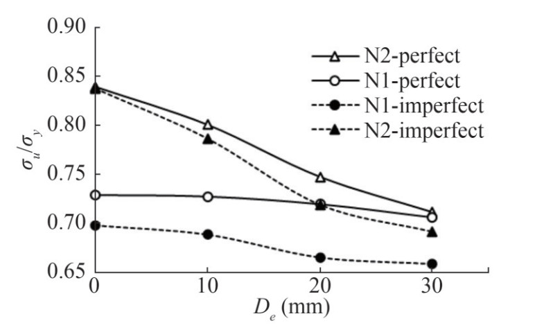 Figure 18 Ultimate strength vs. notch length
6 Conclusions
In this study, the ultimate strength of the cracked and notched stiffened panels under compressive in-plane axial load is studied. The effect of crack position and length is evaluated using the non-linear finite element method. Two stiffened panels with two types of stiffeners, one with a higher and thinner stiffener (C1) and one with a shorter and thicker stiffener (C2) were studied. Despite their different dimensions, both stiffeners have the same cross-section area. Two crack scenarios and one notch scenario were investigated in both cases; I (Intact), CP (A crack in the plating), CS (A crack in the stiffener) and N (A notch on the edge of one stiffener.). It was observed that, in intact form, the ultimate strength of I2 is more than the ultimate strength of I1. As, in I1 case, the stiffeners buckle laterally and the plating deforms accordingly. After buckling stiffeners provide no more support for the plating. The ultimate strength of the cracked stiffened panels (CS and CP cases) is upper than the notched stiffened panels, because in the notched stiffened panels, the effective cross-section of a stiffener is lost. Also, the failure modes of I1 and I2 are not much different from those of cracked and notched stiffened panels until the local buckling of the area around the cracked and notch. More importantly, it was concluded that the position of the crack can have a profound effect on the ultimate strength of the stiffened panels. Cracks in stiffeners can affect the compressive behavior of the stiffened panels more and also they can reduce the ultimate strength of stiffened panels more.
Nomenclature A Plate length B Plate breadth m Number of half-waves in longitudinal direction n Number of half-waves in transverse direction De Crack and notch length E Young's modulus Ne Number of elements at crack tips I Indicator for Intact stiffened panel CS Indicator for Stiffened panel with crack in one stiffener CP Indicator for Stiffened panel with crack in plating N Indicator for Stiffened panel with notch in one stiffener υ Poison ratio σ Stress σmax Maximum stress at the crack tips σu Ultimate strength σy Yield stress σavg Average stress εavg Average strain W0 Initial Imperfection function A0mn Coefficients of initial imperfection function Competing interest The authors have no competing interests to declare that are relevant to the content of this article. -
Figure 1 The studied cracked and notched stiffened panels
Figure 2 Mesh size sensitivity analysis (Ne: Number of the elements at the crack tips)
Figure 3 Plastic strain distribution near the crack tips at the ultimate limit state for CS2 and De=10 mm with various Ne (Number of the element at the crack tips)
Figure 4 Normalized average stress-normalized average strain obtained by the present method and the Shi et al. (2017) study
Figure 5 Average stress-average strain diagram of I1, I2 perfect and imperfect stiffened panels.
Figure 6 The deformation at ultimate strength for the I1 (perfect), I1 (imperfect), I2 (perfect), and I2 (imperfect)
Figure 7 Average stress-average strain diagram of I1, I2, CP1, CP2 with various crack length (De)
Figure 8 The deformation at ultimate strength for the I1, and CP1 with various crack length (De)
Figure 9 The deformation at ultimate strength for the I2, and CP2 various crack length (De)
Figure 10 Average stress-average strain diagram of I1, I2, CS1, CS2 with various crack length (De)
Figure 11 The deformation at ultimate strength for the I1, and CS1 with various crack length
Figure 12 The deformation at ultimate strength for the I2, and CS2 with various crack length
Figure 13 Ultimate strength vs. crack length when crack is placed in the plating
Figure 14 Ultimate strength vs. crack length when crack is placed in the stiffener
Figure 15 The deformation at ultimate strength of I1 and N1 with various notch depth
Figure 16 Average stress-average strain diagram of (I1) and N2 cases
Figure 17 The deformation of I2 and (N2) with various notch depth
Figure 18 Ultimate strength vs. notch length
Table 1 Coefficients of thin-horse mode initial deflection (Yao et al., 1992)
a/b 1 2 3 $1 <a/b<\sqrt{2}$ $\sqrt{2} <a/b<\sqrt{6}$ $\sqrt{6} <a/b<\sqrt{12}$ W01/t 1.115 8 1.142 1 1.145 8 W02/t −0.027 6 −0.045 7 −0.061 6 W03/t 0.137 7 0.228 4 0.307 9 W04/t 0.002 5 0.006 5 0.022 9 W05/t −0.012 3 0.032 6 0.114 6 W06/t −0.000 9 −0.002 2 −0.006 5 W07/t −0.004 3 −0.010 9 0.032 7 W08/t 0.000 8 0.001 0.000 W09/t 0.003 9 −0.004 9 0.000 W10/t −0.000 2 −0.000 5 −0.001 5 W11/t −0.001 1 0.002 7 −0.007 4 Table 2 The summary of the failure modes of the perfect stiffened panels
Case Average stress (MPa) Structural member failure No. of buckling mode half-waves Point in Figure 5 I1 93.8 Side plate buckling 1 A 145.8 Web plate buckling (ultimate strength) 1 B 145.8 Center plate buckling (ultimate strength) 1 B I2 142.7 Side plate buckling 2 E 169.9 Stiffener buckling (ultimate strength) 1 F Table 3 The summary of the failure modes of the imperfect stiffened panels
Case Average stress (MPa) Structural member failure No. of buckling mode half-waves Point in Figure 5 I1 57.7 Side plate buckling 2 C 139.7 Web plate buckling (ultimate strength) 2 D 139.7 Center plate Buckling (ultimate strength) 3 D I2 72.9 Side plating buckling 2 G 76.7 Center plate buckling 3 H 167.5 Stiffener buckling (ultimate strength) 2 H Nomenclature A Plate length B Plate breadth m Number of half-waves in longitudinal direction n Number of half-waves in transverse direction De Crack and notch length E Young's modulus Ne Number of elements at crack tips I Indicator for Intact stiffened panel CS Indicator for Stiffened panel with crack in one stiffener CP Indicator for Stiffened panel with crack in plating N Indicator for Stiffened panel with notch in one stiffener υ Poison ratio σ Stress σmax Maximum stress at the crack tips σu Ultimate strength σy Yield stress σavg Average stress εavg Average strain W0 Initial Imperfection function A0mn Coefficients of initial imperfection function -
Aalberg A, Langseth M, Larsen P (2001) Stiffened aluminium panels subjected to axial compression. Thin-Walled Struct, 39(10): 861-885. https://doi.org/10.1016/S0263-8231(01)00021-0 Anyfantis KN (2020) Ultimate strength of stiffened panels subjected to non-uniform thrust. Int J Nav Archit, 12: 325-342. https://doi.org/10.1016/j.ijnaoe.2020.03.003 Babazadeh A, Khedmati MR (2018) Ultimate strength of cracked ship structural elements and systems: A review. Eng Fail Anal, 89: 242-257. https://doi.org/10.1016/j.engfailanal.2018.03.003 Babazadeh A, Khedmati, MR (2019) Empirical formulations for estimation of ultimate strength of cracked continuous unstiffened plates used in ship structure under in-plane longitudinal compression. Eng Fail Anal, 100: 470-484. https://doi.org/10.1016/j.engfailanal.2019.02.051 Bayatfar A, Khedmati MR, Rigo P (2014) Residual ultimate strength of cracked steel unstiffened and stiffened plates under longitudinal compression. Thin-Walled Struct, 84: 378-392. https://doi.org/10.1016/j.tws.2014.07.002 Brighenti R (2005) Buckling of cracked thin-plates under tension or compression. Thin-Walled Struct, 43(2): 209-224. https://doi.org/10.1016/j.tws.2004.07.006 Cui C, Yang P, Xia T, Du J (2016) Assessment of residual ultimate strength of cracked steel plates under longitudinal compression. Ocean Eng, 121: 174-183. https://doi.org/10.1016/j.oceaneng.2016.05.035 Cui C, Yang P, Li C, Xia T (2017) Ultimate strength characteristics of cracked stiffened plates subjected to uniaxial compression. Thin-Walled Struct, 113: 27-38. https://doi.org/10.1016/j.tws.2017.01.003 Fujikubo M, Harada M, Yao T, Khedmati MR, Yanagihara D (2005a) Estimation of ultimate strength of continuous stiffened panel under combined transverse thrust and lateral pressure Part 2: Continuous stiffened panel. Marine Structures, 18(5-6): 411-427 https://doi.org/10.1016/j.marstruc.2006.01.001 Fujikubo M, Yao T, Khedmati MR, Harada M, Yanagihara D (2005b) Estimation of ultimate strength of continuous stiffened panel under combined transverse thrust and lateral pressure Part 1: Continuous plate. Marine Structures, 18(5-6): 383-410. https://doi.org/10.1016/j.marstruc.2005.08.004 Ghavami K, Khedmati MR (2006) Numerical and experimental investigations on the compression behaviour of stiffened plates. J Constr Steel Res, 62(11): 1087-1100. https://doi.org/10.1016/j.jcsr.2006.06.026 Han P, Ri K, Yun C, Pak C, Paek S (2021) A study on the residual ultimate strength of continuous stiffened panels with a crack under the combined lateral pressure and in-panel compression. Ocean Eng, 234: 109265. https://doi.org/10.1016/j.oceaneng.2021.109265 Hosseinabadi OF, Khedmati MR, Norouzipoor M (2021) Statistical analysis of initial deflection of aluminium plating between stiffeners. Thin-Walled Struct, 161: 107528. https://doi.org/10.1016/j.tws.2021.107528 Ikeda K, Murota K (2022) Bifurcation and Buckling in Structures. 2021: CRC Press. https://doi.org/10.1201/9781003112365 Khedmati MR, Rastani M (2006) Nonlinear elastoplastic behaviour of intermittently welded stiffened plates under inplane compression. Proc Int Conf Offshore Mech Arct Eng-OMAE, 92603: 853-864. https://doi.org/10.1115/OMAE2006-92603 Khedmati MR, Edalat P, Javidruzi M (2009) Sensitivity analysis of the elastic buckling of cracked plate elements under axial compression. Thin-Walled Struct, 47(5): 522-536. https://doi.org/10.1016/j.tws.2008.10.018 Khedmati MR, Zareei MR, Rigo, P (2010) Empirical formulations for estimation of ultimate strength of continuous stiffened aluminium plates under combined in-plane compression and lateral pressure. Thin-Walled Struct, 48(3): 274-289. https://doi.org/10.1016/j.tws.2009.10.001 Khedmati MR, Nouri ZHME, Roshanali MM (2012) A comparative computational investigation on the effects of randomly distributed general corrosion on the post-buckling behaviour of uniaxially loaded plates. Journal of mechanical science and technology, 26, 767-783. https://doi.org/10.1007/s12206-011-1222-1 Kim UN, Choe IH, PaikJK (2009) Buckling and ultimate strength of perforated plate panels subject to axial compression: experimental and numerical investigations with design formulations. Sh Offshore Struct, 4(4): 337-361. https://doi.org/10.1080/17445300902990606 Li S, Kim DK, Benson S (2021) The influence of residual stress on the ultimate strength of longitudinally compressed stiffened panels. Ocean Eng, 231: 108839. https://doi.org/10.1016/j.oceaneng.2021.108839 Liu D, Hao P, Zhang K, Tian K, Wang B, Li G, Xu W (2020) On the integrated design of curvilinearly grid-stiffened panel with non-uniform distribution and variable stiffener profile. Mater Des, 190: 108556. https://doi.org/10.1016/j.matdes.2020.108556 Margaritis Y, Toulios M (2012) The ultimate and collapse response of cracked stiffened plates subjected to uniaxial compression. Thin-Walled Struct, 50(1): 157-173. https://doi.org/10.1016/j.tws.2011.09.008 Ozdemir M, Ergin A, Yanagihara D, Tanaka S, Yao T (2018) A new method to estimate ultimate strength of stiffened panels under longitudinal thrust based on analytical formulas. Mar Struct, 59: 510-535. https://doi.org/10.1016/j.marstruc.2018.01.001 Paik JK (2008) Residual ultimate strength of steel plates with longitudinal cracks under axial compression-experiments. Ocean Eng, 35(17-18): 1775-1783. https://doi.org/10.1016/j.oceaneng.2008.08.012 Paik JK (2009) Residual ultimate strength of steel plates with longitudinal cracks under axial compression—nonlinear finite element method investigations. Ocean Eng, 36(3-4): 266-276. https://doi.org/10.1016/j.oceaneng.2008.12.001 Putranto T, Kõrgesaar M, Jelovica J, Tabri K, Naar H (2021) Ultimate strength assessment of stiffened panel under uni-axial compression with non-linear equivalent single layer approach. Mar Struct, 78: 103004. https://doi.org/10.1016/j.marstruc.2021.103004 Shaw D, Huang Y (1990) Buckling behavior of a central cracked thin plate under tension. Eng Fract Mech, 35(6): 1019-1027. https://doi.org/10.1016/0013-7944(90)90129-5 Shi XH, Zhang J, Soares CG (2017) Experimental study on collapse of cracked stiffened plate with initial imperfections under compression. Thin-Walled Struct, 114: 39-51. https://doi.org/10.1016/j.tws.2016.12.028 Song ZJ, Xu MC, Moan T, Pan J (2019) Dimensional and similitude analysis of stiffened panels under longitudinal compression considering buckling behaviours. Ocean Eng, 187: 106188. https://doi.org/10.1016/j.oceaneng.2019.106188 Ueda Y, Yao T (1985) The influence of complex initial deflection modes on the behaviour and ultimate strength of rectangular plates in compression. Journal of Constructional Steel Research, 5(4): 265-302. https://doi.org/10.1016/0143-974X(85)90024-0 Xia T, Yang P, Hu K, Cui C (2018) Combined effect of imperfections on ultimate strength of cracked plates under uniaxial compression. Ocean Eng, 150: 113-123. https://doi.org/10.1016/j.oceaneng.2017.12.060 Xu MC, Soares CG (2012) Assessment of the ultimate strength of narrow stiffened panel test specimens. Thin-Walled Struc, 55: 11-21. https://doi.org/10.1016/j.tws.2012.02.006 Yao T, Nikolov P, Miyagawa Y (1992) Influences of welding imperfections on stiffness of rectangular plate under thrust. mechanical effects of welding: Karlsson, L., Lindgren, LE., Jonsson, M. (eds) Mechanical Effects of Welding. International Union of Theoretical and Applied Mechanics. Springer, Berlin, Heidelberg. https://doi.org/10.1007/978-3-642-84731-8_26 Yu CL, Chen YT, Yang S, Liu Y, Lu GC (2018) Ultimate strength characteristic and assessment of cracked stiffened panel under uniaxial compression. Ocean Eng, 152: 6-16. https://doi.org/10.1016/j.oceaneng.2018.01.015 Zhang J, Shi XH, Soares CG, Liu J (2022) Ultimate strength of stiffened panels with a crack and pits under uni-axial longitudinal compression. Sh Offshore Struct, 17(2): 319-338. https://doi.org/10.1080/17445302.2020.1827805 Zhang S, Khan I (2009) Buckling and ultimate capability of plates and stiffened panels in axial compression. Mar Struct, 22(4): 791-808. https://doi.org/10.1016/j.marstruc.2009.09.001
