
Ultimate Strength of Platings Under Uniaxial Compression with Edges Elastically Restrained Against Torsion: A New Comprehensive Approach
https://doi.org/10.1007/s11804-024-00426-1
-
Abstract
The ultimate strength of platings under compression is one of the most important factors to be addressed in the ship design. Current Rules for ship structural design generally provide explicit strength check criteria against buckling for simply supported and clamped platings. Nevertheless, ship platings generally exhibit an intermediate behaviour between the simple support and the clamped conditions, which implies that the torsional stiffness of supporting members should be duly considered. Hence, the main aim of this study is the development of new design formulas for the ultimate strength of platings under uniaxial compression, with short and/or long edges elastically restrained against torsion. In this respect, two benchmark studies are performed. The former is devoted to the development of new equations for the elastic buckling coefficients of platings with edges elastically restrained against torsion, based on the results of the eigenvalue buckling analysis, performed by Ansys Mechanical APDL. The latter investigates the ultimate strength of platings with elastically restrained edges, by systematically varying the plate slenderness ratio and the torsional stiffness of supporting members. Finally, the effectiveness of the new formulation is checked against a wide number of finite element (FE) simulations, to cover the entire design space of ship platings.Article Highlights● New formulas are developed for the elastic buckling coefficient for platings with short, long and all edges elastically restrained against torsion.● Eigenvalue buckling analysis and nonlinear FE analysis of platings are conducted.● Benchmark on the ultimate strength of platings under compression is studied.● Results demonstrate the effectiveness of the new approach. -
1 Introduction
The ultimate strength assessment of platings under compression is a key factor of ship design, as buckling is one of the main failure modes of ship structural elements. As it will be further outlined in Section 2, in the last century the elastic bucking and the ultimate strength of platings under compression have been widely investigated by a variety of researchers throughout the world in order to improve the knowledge of structural instability and develop practical design formulas for the buckling strength check of isolate plate panels. In this respect, recognising the important role of buckling strength check criteria, the International Association of Classification Societies, from now on IACS, delivered a harmonized methodology, endorsed in the "Common Structural Rules for Bulk Carriers and Oil Tankers" (IACS, 2022) and recently extended to all ship types by the Unified Requirement UR S35 "New Unified Requirement On Buckling Strength Assessment of Ship Structural Elements" (IACS, 2023) that will enter into force on 1st July 2024.
The harmonized methodology is based on the buckling toolbox for bulk carriers and oil tankers, as it is widely accepted by the scientific community and technically sound. In this respect, the ultimate strength check of isolated plate panels under compression is carried out considering the simple support and the clamped boundary conditions at the short and/or long edges of the plate panel. The first boundary condition is on the safe side, as it neglects the torsional stiffness of supporting members and slightly underestimates the ultimate strength capacity of the plate panel. On the contrary, assuming the clamped boundary condition, corresponding to an infinite torsional stiffness of supporting members, the ultimate strength capacity is slightly overestimated. Rules also allow estimating intermediate boundary conditions by some corrective factors, depending on the section type and the scantling of longitudinal stiffeners and transverse primary supporting members.
Really, ship platings exhibit an intermediate behaviour between the simple support and clamped boundary conditions, which implies that the buckling toolbox, currently endorsed by Rules, should be updated to address for real boundary conditions and a more rationale design of ship platings against instability. Based on these remarks, the main aim of this research is to develop practical design formulas for the ultimate strength assessment of platings with short and/or long edges elastically restrained against torsion, with the main aim of providing a contribution for a possible update of Rules and guidelines for the ship structural design. Hence, the following main topics are dealt with:
1) New design formulas for the elastic buckling coefficient of platings with short, long and all edges elastically restrained against torsion, are developed, based on the results of the eigenvalue buckling analysis, carried out by Ansys Mechanical APDL (Ansys, 2022), by systematically varying the main parameters of the isolated plate panel, namely the aspect ratio and the torsional stiffness of longitudinal stiffeners and transverse primary supporting members.
2) Current design formulas for the ultimate strength of platings, based on the simple support and clamped boundary conditions, are extended to the general case of platings with edges elastically restrained against torsion. The effectiveness of this assumption is investigated by a wide number of nonlinear FE simulations, carried out by Ansys Mechanical APDL, to cover the entire design space of ship platings and relevant supporting members.
3) The effectiveness of the new formulation, that includes the simple support and clamped boundary conditions as special cases, is further investigated by means of a new data set of FE simulations, by randomly varying the main parameters of ship platings, namely the slenderness ratio and the torsional stiffness of supporting members at short and long edges.
The paper is organized as follows. Section 2 provides a brief historical review about the elastic buckling strength and ultimate capacity of platings under compression. Section 3 focuses on some issues, to be dealt with before performing the eigenvalue and nonlinear buckling analysis by Ansys Mechanical APDL. The new formulas for the elastic buckling coefficient of platings with edges elastically restrained against torsion are developed in Section 4. Section 5 investigates the extension of the Rule formula for the ultimate strength of platings under compression to the general case of platings with elastically restrained edges. Section 6 investigates the effectiveness of the new formulation that accounts for the torsional stiffness of longitudinal stiffeners and transverse primary supporting members and compares the results obtained by the new formulas with the relevant ones obtained by the "Common Structural Rules for Bulk Carriers and Oil Tankers" (IACS, 2022) and the Recommended Practice RP-C201 "Buckling strength of plated structures" (DnV, 2023). Finally, Section 7 summarizes the main findings of the research and provides some suggestions for possible improvements of current Rules and guidelines and for future research activities.
2 A brief historical review
2.1 Elastic buckling strength of platings under uniaxial compression
The first pioneering works on the elastic buckling of platings date back to the last decade of the 19th century, when Bryan (1890) solved the Navier partial differential equations for the stability analysis of thin plates by minimizing the total potential energy functional and determined the critical buckling load of simply supported platings under uniaxial compression. In the following years, Timoshenko (1910) investigated the buckling strength of platings with simply supported loaded edges and different boundary conditions at the unloaded ones. Two decades later, the critical buckling load and buckled shape provided by Timoshenko (1910) were confirmed by the experimental campaign carried out by Bridget et al. (1934) at the Guggenheim Aeronautical Laboratory of the California Institute of Technology, under the supervision of von Kármán. The problem of long platings, with boundary conditions different from the simple support ones, was further investigated in the following decade by Strandhagen (1944) and Roettinger (1947), who applied the finite Fourier integral transformation. In the following years attention was paid to the elastic buckling of finite length platings, to investigate the incidence of the aspect ratio on the plating capacity, by Timoshenko and Gere (1961) and Allen and Bulson (1980). Some years later, Fujikubo and Yao (1999) developed an analytical formula to predict the elastic buckling strength of stiffened panels under biaxial compression, accounting for the plate/stiffener interaction and welding residual stresses. They concluded that the elastic buckling strength of ship platings is generally increased by the torsional stiffness of longitudinal supporting members, but this increase is partly counterbalanced by the presence of welding residual stresses. Since then, this topic has been well established and no substantial improvements have been gained. Nowadays, the design values of the buckling coefficients for simply supported and clamped platings are generally taken equal to kxAS=4.00 and kxAC=6.97, respectively (IACS, 2022). Similarly, the elastic buckling coefficient kxSSLC of platings simply supported at short edges and clamped at the long ones is taken equal to 6.97. Finally, the buckling coefficient kxSCLS of platings clamped at short edges and simply supported at the long ones is determined by the approximate formulation provided by Eq. (1), as a function of the aspect ratio α (IACS, 2022):
$$ k_{x}^{\text {SCLS }}=\left\{\begin{array}{l} 4.00+2.74\left(\frac{4-\alpha}{3}\right)^{4} \text { for } \alpha<4 \\ 4.00 \text { for } \alpha \geqslant 4 \end{array}\right. $$ (1) These formulas, endorsed in the "Common Structural Rules for Bulk Carriers and Oil Tankers" (IACS, 2022), have been recently extended to all ship types by the "Unified Requirement on Buckling Strength Assessment of Ship Structural Elements" (IACS, 2023), proving the great interest of Classification Societies in developing common and technically sound buckling strength check criteria.
The above-mentioned research activities focused on the buckling strength of platings simply supported or clamped at short/long edges. Nevertheless, ship structures generally exhibit an intermediate behaviour between the simple support and clamped boundary conditions. In this respect, since the mid-40 s attention was also paid to the incidence of the torsional stiffness of supporting members on the plating buckling strength. Lundquist and Stowell (1942) investigated the buckling strength of platings under compression, simply supported at all edges and elastically restrained against torsion at the unloaded ones. They provided a design chart for the assessment of the buckling coefficient as a function of the aspect ratio and torsional stiffness of supporting members at the unloaded edges. Some years later, Evans (1960) performed a wide experimental campaign, devoted to investigating the elastic buckling strength of simply supported platings under uniaxial compression and elastically restrained against torsion at the long ones. He also derived a closed-form expression of the buckling strength, as a function of the torsional stiffness of supporting members. McKenzie (1964) investigated the elastic buckling of platings under the combined action of biaxial compressive loads, bending and shear, with rotationally restrained supports at the loaded edges. Really, in the following decades no further advances were gained, at the best of the author's knowledge, until the milestone work by Paik and Thayamballi (2000), who systematically investigated the buckling strength of steel platings, elastically restrained at long and/or short edges, and developed simple design formulas as a function of the torsional stiffness of supporting members. The validity of the closed-form equations was checked against a set of FE simulations. In this respect, Paik and Thayamballi (2000) proposed the formula provided by Eq. (2) for the elastic buckling coefficient of platings simply supported at the short edges and elastically restrained at the long ones:
$$ k_{x}^{\text {SSLE }}=\left\{\begin{array}{l} 0.396 \varsigma_{L}^{3}-1.974 \varsigma_{L}^{2}+3.565 \varsigma_{L}+4 \; { for }\; 0 \leqslant \varsigma_{L}<2 \\ 6.951-\frac{0.881}{\varsigma_{L}-0.4} \text { for } 2 \leqslant \varsigma_{L}<20 \\ 7.025 \text { for } \varsigma_{L} \geqslant 20 \end{array}\right. $$ (2) Having denoted by $\varsigma_{L}=G J_{L}/(2 b D)$ the nondimensional stiffness ratio of longitudinal supporting members, with torsional constant $J_{L}$. It is noticed that the torsional rigidity is reduced by one-half to account for the incidence of adjacent platings. Reference is made to the list of symbols and acronyms for the meaning of all remaining quantities. A similar expression was proposed for the elastic buckling coefficient $k_{x}^{\text {SELS }}$ of simply supported platings elastically restrained against torsion at the short edges, according to Eq. (3):
$$ k_{x}^{\mathrm{SELS}}=f_{4}(\alpha) \varsigma_{T}^{4}+f_{3}(\alpha) \varsigma_{T}^{3}+f_{2}(\alpha) \varsigma_{T}^{2}+f_{1}(\alpha)+f_{0}(\alpha) $$ (3) where reference is made to Appendix A for the analytical formulation of the nondimensional weighting functions $f_{i}(\alpha)$, depending on the panel aspect ratio. Finally, the elastic buckling coefficient of platings elastically restrained against torsion at all edges was expressed by a linear combination of the previous boundary conditions, according to Eq. (4):
$$ k_{x}^{\mathrm{AE}}=k_{x}^{\mathrm{SSLE}}+k_{x}^{\mathrm{SELS}}-k_{x}^{\mathrm{AS}} $$ (4) More recently, Piscopo (2012) determined the elastic buckling coefficient of platings with all edges elastically restrained against torsion by the energy method, regarding the plate panel as part of a wide stiffened panel, reinforced by longitudinal stiffeners and transverse supporting members. In this respect, the eigenvalue buckling problem was solved adding the torsional strain energy of supporting members.
2.2 Ultimate strength of platings under uniaxial compression
The first pioneering studies on the ultimate strength of platings under compression date back to the mid-30 s, thanks to the increasing interest in exploring the ultimate capacity of thin platings beyond the elastic limit, especially in the aeronautic sector. In this respect, the first experimental campaign was carried out by the Bureau of Standards in cooperation with the Navy Department of the Bureau of Aeronautics. These experiments showed that the ultimate strength of platings under compression is independent of the width and length of the plate panel and proportional to the square of the plate thickness. Starting from the results of this experimental campaign on 24 specimens made of light alloy, stainless steel, nickel/copper alloy and nickel, von Kármán et al. (1932) derived the first formula for the ultimate to yield strength ratio of platings under uniaxial compression, provided by Eq. (5):
$$ \phi_{u}=\frac{C}{\beta} $$ (5) Having denoted by C a nondimensional parameter lying between 1.24 and 1.90 for platings with long edges free to move and fully restrained in the horizontal plane, respectively. They also recognized that there were no systematic differences between the tested materials, even if a slight systematic decrease of C with the plating thickness was found, probably due to the flexibility of the testing jig used in the experiments. Since the end of 1932, a new and wide experimental campaign was conducted by Vasta at the Experimental Model Basin of the U. S. Navy. Some years later the design formula provided by Eq. (6) was developed by Frankland (1940), based on the data set obtained by the experimental campaign:
$$ \phi_{u}=\frac{2.25}{\beta}-\frac{1.25}{\beta^{2}} $$ (6) This formula represents a milestone for the ultimate strength of platings under compression and it is nowadays endorsed in the incremental iterative procedure for the hull girder ultimate strength assessment (IACS, 2022). Some years later Winter (1947) performed additional tests on 25 U-beams, in order to investigate the effectiveness of the formula provided by von Kármán et al. (1932), and developed the design formula provided by Eq. (7):
$$ \phi_{u}=\frac{1.90}{\beta}-\frac{1.09}{\beta^{2}} $$ (7) In 1959 the American Bureau of Ships requested the Model Basin of the U. S. Navy to conduct a new experimental campaign, devoted to update the Frankland (1940) formula, considering the new types of steels and light alloys employed in the shipbuilding sector. In this respect, 50 panels were tested and a new ultimate strength formula, provided by Eq. (8), was developed by Conley et al. (1963):
$$ \phi_{u}=\frac{1.82}{\beta}-\frac{0.82}{\beta^{2}} $$ (8) This formula was modified slightly later by Faulkner in the discussion session of a paper by Caldwell (1965). The new formula, provided by Eq. (9), has an excellent agreement with strut-test data and box-girder bridge reviews (Faulkner, 1975):
$$ \phi_{u}=\frac{2.00}{\beta}-\frac{1.00}{\beta^{2}} $$ (9) In the mid-80 s a new experimental campaign was documented by Scheer et al. (1987) and a generalized form of Winter (1947) equation was developed for platings with longitudinal edges free to move in the horizontal plane. The new ultimate strength formula, provided by Eq. (10), was included in the first edition of the International Standard DIN18800-3 "Steel Structures-Part 3: Stability-Safety against buckling of plates" (DIN, 1990):
$$ \phi_{u}=(1.25-0.12 \psi)\left(\frac{1.00}{\lambda}-\frac{0.22}{\lambda^{2}}\right) $$ (10) In Eq. (10) ψ is the maximum to minimum stress ratio on the loaded edges of the plate panel, equal to 1 for uniaxial compression, while λ denotes the reference degree of slenderness of the plate panel, to be determined by Eq. (11):
$$ \lambda=\beta \sqrt{\frac{12\left(1-v^{2}\right)}{\pi^{2} k_{x}}} $$ (11) As a function of the material Poisson modulus ν and the elastic buckling coefficient kx that, in turn, depends on the boundary conditions of the plate panel. In the same years, Guedes Soares and Kmiecik (1993) investigated the ultimate strength of platings, considering different patterns of initial distortions and accounted for the variability of steel mechanical properties by Monte Carlo simulation. They verified that the variability of the plate ultimate strength mainly depends on the slenderness of the plate panel. Some years later, Guedes Soares and Gordo (1996a and b) investigated the ultimate strength of platings subjected to transverse compression and biaxial compressive loads, accounting for initial distortions, welding residual stresses and lateral pressure loads. The ultimate strength formula provided by Eq. (10) was included in the first edition of the "Common Structural Rules for Bulk Carriers" (IACS, 2006a) and the "Common Structural Rules for Oil Tankers" (IACS, 2006b) and nowadays it is endorsed in the "Common Structural Rules for Bulk Carriers and Oil Tankers" (IACS, 2022) as well as in the recently released guidelines "New Unified Requirement on Buckling Strength Assessment of Ship Structural Elements" (IACS, 2023). Some years later, this equation format was partly modified in the first edition of the European Standard EN1993-1-5 "Eurocode 3-Design of steel structures-Part1-5: Plated Structural elements" (2019), according to Eq. (12):
$$ \phi_{u}=\frac{1.00}{\lambda}-\frac{0.055}{\lambda^{2}}(3+\psi) $$ (12) This design formula, that generalizes the Winter (1947) one, was also included in the Recommended Practice RP-C201 "Buckling strength of plated structures" (DnV, 2023). Finally, in the last decade several practical design formulations have been also proposed by a variety of researchers throughout the world. Cui et al. (2002) applied a simplified analytical method by combining the elastic large-deflection analysis with the rigid-plastic solution for plate panels and developed a new analytical formulation for the ultima strength of platings under compression. Masaoka and Mansour (2004) developed a new design equation for unstiffened plates, considering the incidence of geometrical imperfections and welding residual stresses. They concluded that the analytical method, based on the large deflection analysis and the rigid-plastic theory, is not always accurate and the nonlinear FE analysis is the most reliable technique to assess the plating ultimate strength. Paik et al. (2004) investigated the influence of the initial deflection field on the ultimate strength of platings under compression and concluded that the buckling deflection mode is a good representation for a somewhat pessimistic evaluation of the ultimate capacity, on the safe side. Piscopo and Scamardella (2018) carried out a benchmark study, devoted to investigating the ultimate capacity of simply supported platings considering different levels of geometrical imperfections and welding residual stresses, as well as two boundary conditions for the in-plane motions of the unloaded longitudinal edges, namely the free and fully restrained ones. More recently, additional advances have been also gained with reference to the ultimate strength assessment of platings affected by random corrosion wastage, as proved by the works of Wang et al. (2018), Feng et al. (2020), Piscopo and Scamardella (2019, 2020, 2021), among others.
3 Some preliminary remarks
3.1 The FE model
The plate panel, with length a and breadth b, is simply supported at all edges and uniformly loaded on the short ones, as depicted in Figure 1. In addition, the short and/or long edges are elastically restrained against torsion by transverse supporting members and longitudinal stiffeners, respectively. Besides, the long edges are free to move in the horizontal plane, as it typically occurs when the ultimate strength of the isolated plate panel needs to be investigated. The validity of this assumption will be checked in Subsection 3.5, where a comparative analysis between the Rule formula, provided by Eq. (12), and the ultimate strength simulations, carried out by Ansys APDL, is performed. Let us denote by
$$ \varsigma_{L}=G J_{L}/2 b D\left(\varsigma_{T}=G J_{T}/2 b D\right) $$ 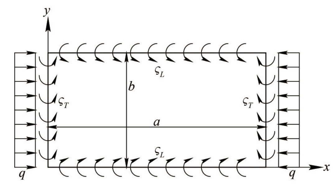 Figure 1 Layout of the plate panel
the nondimensional torsional stiffness of longitudinal stiffeners (transverse supporting members) for continuously stiffened platings, equal to 0 and Inf for the simple support and clamped boundary conditions, respectively. The nondimensional parameter ςL (ςT) depends on the torsional constant of longitudinal stiffeners (transverse supporting members) JL (JT) and the bending stiffness D of the plate panel. The torsional stiffness ratio of supporting members at the long sides of the plate panel generally lies between 0.05 and 3.00, without exceeding 5.00. The same parameter at short edges generally ranges between 0.10 and 8.00, without exceeding 13.00 (Paik and Thayamballi, 2000).
The reference layout of the plate panel under uniaxial compression, with elastically restrained edges against torsion, is resembled by Ansys Mechanical APDL (Ansys, 2022). The plate panel is modelled by the four-node SHELL181 element, with five integration points along the plate thickness, six freedom degrees at each node that make it suitable for linear, large rotation and large strain nonlinear applications involving thin up to moderately thick shell structures. The torsional stiffness of supporting members is included in the FE model by the COMBIN14 spring-damper element, having both longitudinal and torsional stiffness capabilities. The spring constant per unit length k =GJ/(2Δ)=ζbD/Δ of each COMBIN14 element, located at the long (short) edges of the plate panel, depends on the torsional constant of the longitudinal (transverse) supporting member and on the relevant element mesh size Δ. Finally, the elastic-perfectly plastic material model is employed, as it typically occurs for nonlinear FE analysis of ship structures. In this respect, the material model is linear up to the yield strength, with angular coefficient equal to the material elastic modulus. Once the yield strength is reached, according to the Von-Mises criterion, no strain hardening effects are considered on the safe side, if a further increase of the strain field occurs beyond the yield strain.
3.2 The initial deflection field
The Annex C of the International Standard EN1993-1-5 "Eurocode 3-Design of steel structures-Part 1 ‒ 5: Plated Structural elements" (ECS, 2019) establishes that the imperfections, affecting the ultimate strength of platings under compression, can be subdivided into two main categories, namely: (ⅰ) the geometrical imperfections, caused by manufacturing processes and unintentional eccentric loads and (ⅱ) the structural imperfections, related to the residual stresses due to the welding process and the deviations of the material mechanical properties from the relevant mean values. Nevertheless, equivalent geometric imperfections, consisting of a simplified combination of the geometrical and structural ones (ECS, 2019), are generally endorsed in the FE analysis. The equivalent deflection field can be schematized by the thin-horse or the buckling deflection modes. The former consists of a trigonometric series, whose weighting factors up to the 11th mode have been provided by Ueda and Yao (1985), as a function of the plate aspect ratio. The buckling deflection mode, instead, is based on a trigonometric displacement field with half-wave number in the longitudinal direction m corresponding to the buckled shape of the plate panel (Timoshenko and Gere, 1961) and fulfilling the condition provided by Eq. (13):
$$ \alpha \leqslant \sqrt{m(m+1)} $$ (13) In the following, the vertical coordinates of each node of the FE model are varied according to the trigonometric function provided by Eq. (14):
$$ w(x, y)=w_{\max } \sin \left(\frac{m {\rm{\mathsf{π}}} x}{a}\right) \sin \left(\frac{{\rm{\mathsf{π}}} y}{b}\right) $$ (14) having denoted by wmax the maximum amplitude of the displacement field that is set equal to b/200 (ECS, 2019). By way of illustration, Figure 2 provides the initial displacement field of a simply supported panel under uniaxial compression with aspect ratio equal to 2 obtained in the pre-processing phase of the elasto-plastic collapse analysis, carried out by Ansys Mechanical APDL.
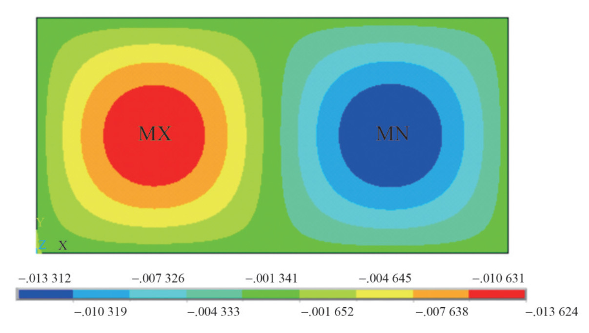 Figure 2 Initial displacement field of simply supported plating under uniaxial compression
The number of half-waves in the longitudinal direction for elastically restrained and clamped platings has been set based on the results of the eigenvalue buckling analysis. Besides, no welding residual stresses are considered in the FE simulations, as they are generally quickly shaken over time (Zhang, 2016). Nevertheless, it must be pointed out that the incidence of the residual stress field is in some cases appreciable, as stressed by Khan and Zhang (2011) who concluded that the ultimate capacity of platings, with slenderness ratios equal to 1.50 and 1.79, decreases by 11~13% due to the applied compressive residual stress field.
3.3 Selection of mesh size
Before investigating the ultimate strength of platings with elastically restrained supports, the selection of mesh size needs to be preliminarily studied, to ensure the convergence of the FE solution, focusing on a reference plate panel, simply supported at all edges, with breadth b=800 mm, α=3, E=205.8 GPa and σy=352.8 MPa. The number of divisions of the short edge ny is systematically increased from 10 to 40 and the ultimate to yield strength ratio is assessed at some selected values of the slenderness ratio β that, in turn, is varied from 1.0 to 5.0 with 0.5 step. Table 1 provides the results of the FE simulations. Assuming the ultimate to yield strength ratio of the very fine mesh size as reference value, the maximum percentage error increases among with the slenderness ratio and reaches a maximum value equal to 5.94%, 1.46% and 0.70% for the very coarse, coarse and fine mesh sizes, respectively. Based on current results, the fine mesh size is accurate enough for practical design purposes and it is selected for all the FE simulations carried out in Sections 4, 5 and 6.
Table 1 Convergence of solution-Ultimate to yield strength ratios of simply supported platings (α=3)β Very coarse mesh Coarse mesh Fine mesh Very fine mesh ny=10 (300 elements) ny=20 (1 200 elements) ny=30 (2 700 elements) ny=40 (4 800 elements) 1.0 0.986 8 0.984 9 0.985 2 0.985 2 1.5 0.897 1 0.890 3 0.889 0 0.887 7 2.0 0.738 2 0.726 8 0.725 1 0.724 9 2.5 0.617 0 0.609 6 0.608 6 0.607 1 3.0 0.542 0 0.533 3 0.531 4 0.530 6 3.5 0.489 8 0.479 6 0.477 8 0.476 8 4.0 0.451 2 0.437 9 0.436 3 0.434 6 4.5 0.419 2 0.405 0 0.401 3 0.400 2 5.0 0.390 9 0.374 3 0.371 5 0.368 9 3.4 Design space of plate panels
The aspect ratio of platings, located at the deck and bottom of contemporary oil tankers and bulk carriers, with an overall length ranging from 150 to 400 m, generally ranges from 3.5 to 6.7, with length and breadth lying in the intervals 2.5~6.0 m and 0.7~1.0 m, respectively (Zhang, 2016). The plating thickness, instead, generally ranges between 12 and 36 mm, which implies that the slenderness ratio lies between 1.0 and 2.5, with a mean value equal to 2.0 (Zhang, 2016). Nevertheless, as previously said, the IACS recently released the "New Unified Requirement on Buckling Strength Assessment of Ship Structural Elements" UR S35 (IACS, 2023), extending the buckling toolbox, endorsed in the "Common Structural Rules for Bulk Carriers and Oil Tankers" (IACS, 2022), to all ship types. This novelty requires an extension of the design space of plate panels, to include other ship types, such as containerships (Yi et al., 2021). As concerns the torsional stiffness of longitudinal stiffeners and transverse primary supporting members, the nondimensional parameter ςL generally ranges between 0.05 and 3.0, without exceeding 5.0, while ςT generally lies in the range from 0.10 to 8.0 and it usually does not exceed 13.0 (Paik and Thayamballi, 2000). Table 2 provides the plate parameters endorsed in the benchmark study, in order to cover the entire design space of ship platings and supporting members.
Table 2 Design space of plate panelsPlate aspect ratio, α 1.0‒5.0 Plate slenderness ratio, β 0.1‒5.0 Torsional constant of longitudinal stiffeners/transverse supporting members, ςL/ςT 0.5, 1.0, 5.0, 10.0 Finally, two types of reference boundary conditions are selected in the benchmark study, as outlined in Table 3. Particularly, 3 reference cases refer to platings with perfect boundary conditions and 3 additional cases refer to plate panels with short and/or long edges elastically restrained against torsion.
Table 3 Reference conditions of the benchmark studyBoundary condition Reference case Acronym Perfect Short edges clamped and long edges simply supported SCLS Short edges simply supported and long edges clamped SSLC All edges clamped AC Elastically restrained Short edges elastically retrained against torsion and long edges simply supported SELS Short edges simply supported and long edges elastically restrained against torsion SSLE All edges elastically restrained against torsion AE 3.5 Platings with simply supported edges
The effectiveness of the FE model is preliminarily investigated, considering a reference plating with all edges simply supported, in order to compare the FE results with the relevant values available in literature. In this respect, Figure 3(a) provides the elastic buckling coefficient, obtained by the eigenvalue buckling analysis, as a function of the aspect ratio. A very good agreement with the theoretical values is gathered. Figure 3(b), instead, depicts the ultimate to yield strength ratio: also in this case a very good agreement with the design formula provided by Eq. (12) and endorsed in the Recommended Practice RP-C201 "Buckling strength of plated structures" (DnV, 2023) is recognized in the entire design space of the slenderness parameter.
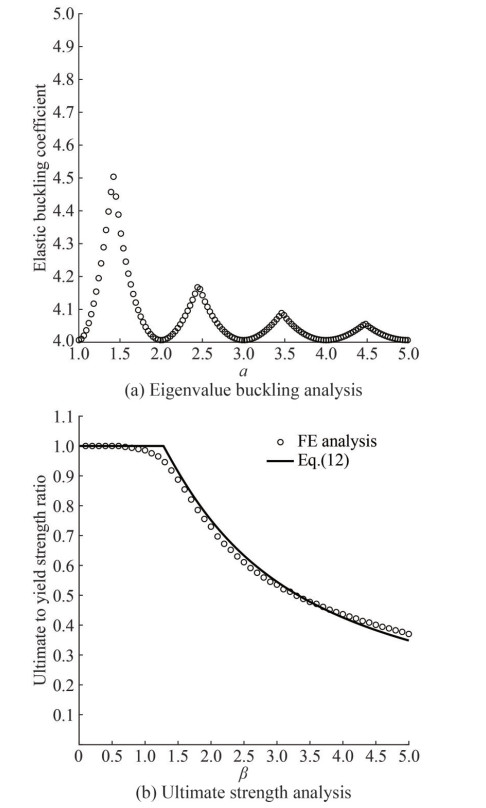 Figure 3 Eigenvalue and ultimate strength analysis-simply supported platings at all edges
4 Eigenvalue buckling analysis
4.1 Platings with perfect boundary conditions
The first data set of FE simulations refers to platings with perfect boundary conditions, as outlined in the first part of Table 3. The design curves for the buckling coefficients of platings with short, long and all edges clamped, are provided by Eq. (15.1), (15.2) and (15.3), after performing the best-fit analysis of FE results:
$$ k_{x}^{\mathrm{SCLS}}=4+3 \alpha^{-2} $$ (15.1) $$ k_{x}^{\mathrm{SSLC}}=7 $$ (15.2) $$ k_{x}^{\mathrm{AC}}=7+3 \alpha^{-2} $$ (15.3) The effectiveness of the design formulas is proved by Figure 4, where they are compared with the FE results. The triangle, square and diamond points refer to the FE values, while the continuous, dashed and pointed dashed lines refer to the approximate design formulas provided by Eq. (15.1), (15.2) and (15.3).
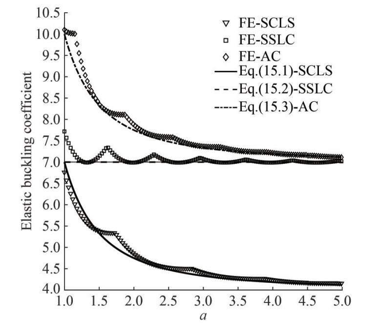 Figure 4 Elastic buckling coefficients-platings with perfect boundary conditions
Reference is also made to Table B.1 of Appendix B, that provides the buckling coefficients at some selected values of the plate aspect ratio.
4.2 Platings with elastically restrained edges against torsion
The 3 reference conditions for platings with short/long edges elastically restrained against torsion are investigated to develop new design formulas for the elastic buckling coefficient, as a function of the torsional stiffness of longitudinal stiffeners and transverse primary supporting members. The design curves, provided by Eq. (16.1), (16.2) and (16.3), are obtained by best-fit analysis of FE simulations:
$$ k_{x}^{\mathrm{SELS}}=4+3 \frac{\zeta_{T}}{\zeta_{T}+0.6} \alpha^{-2 \frac{\zeta_{T}}{\zeta_{T}+0.3}} $$ (16.1) $$ k_{x}^{\mathrm{SSLE}}=4+3 \frac{\zeta_{L}}{\zeta_{L}+0.6} $$ (16.2) $$ k_{x}^{\mathrm{AE}}=4+3\left[\frac{\zeta_{L}}{\zeta_{L}+0.6}+\frac{\zeta_{T}}{\zeta_{T}+0.6} \alpha^{-2 \frac{\zeta_{r}}{\zeta_{T}+0.3}}\right] $$ (16.3) In this respect, it must be preliminarily pointed out that these design curves provide the reference buckling coefficients for platings simply supported at all edges when ζT=ζL=0. Besides, they also resemble the design curves, provided by Eq. (15.1), (15.2) and (15.3), when ζT →∞ and ζL →∞. Also in this case, the effectiveness of the design formulas is checked against the relevant FE values. Figures 5(a)~(d) refer to platings with different values of the torsional stiffness ratio, equal to 0.5, 1.0, 5.0 and 10.0, to cover the entire design space of longitudinal stiffeners and transverse primary supporting members. Also in this case, an appreciable agreement of the new design curves with the FE results is gathered. Reference is also made to Table B.2, B.3 and B.4 of Appendix B that provide the buckling coefficients for platings with short, long and all edges elastically restrained against torsion, obtained by the eigenvalue buckling analysis carried out by Ansys Mechanical APDL.
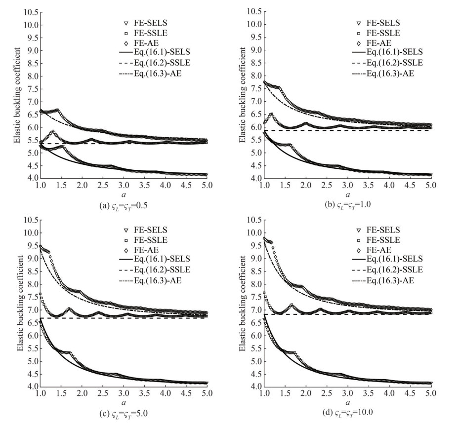 Figure 5 Elastic buckling coefficients-platings with edges elastically restrained against torsion
5 Ultimate strength analysis
5.1 Platings with perfect boundary conditions
The ultimate strength of platings with clamped edges is preliminarily investigated. The results of FE simulations are plotted in Figure 6 for a reference plate panel with an aspect ratio α equal to 4.0, together with the design curve provided by Eq. (12), combined with the elastic buckling coefficients for clamped platings, provided by Eqs. (15.1), (15.2) and (15.3). By the comparative analysis with the FE simulations, a very good agreement is recognized in the entire design space of ship platings. Some differences between the FE results and the relevant values provided by the new design equations arise for platings with long and all edges clamped, combined with a slenderness ratio greater than 4.0. Nevertheless, as previously said, the slenderness ratio of typical ship platings generally ranges from 1.0 to 2.5 (Zhang, 2016), which implies that these slight differences are expected to have no incidence on the plate design against buckling. By Figure 6 it can be also gathered that platings with clamped short edges exhibit almost the same ultimate capacity of simply supported platings. On the contrary, a consistent increase of the ultimate strength occurs when the long edges are clamped. Reference is also made to Table C.1 of Appendix C that provides the ultimate to yield strength ratios for platings with clamped edges and an aspect ratio α equal to 4.0 at some selected values of the slenderness parameter.
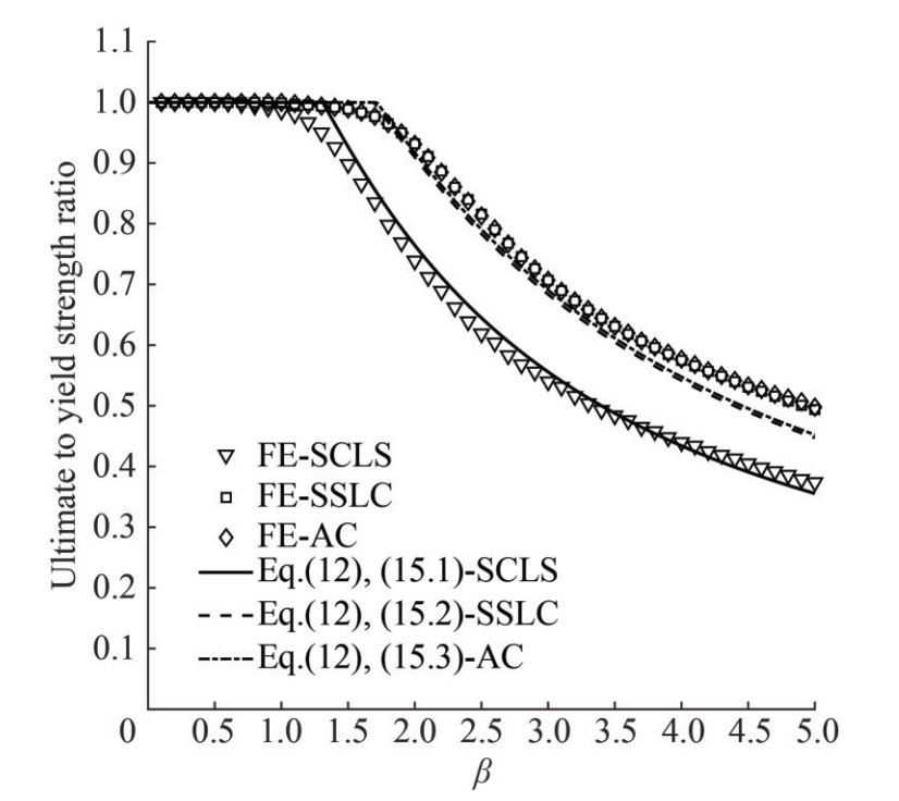 Figure 6 Ultimate to yield strength ratios-platings with perfect boundary conditions (α=4.0)
5.2 Platings with elastically restrained edges against torsion
The ultimate to yield strength ratios of platings with edges elastically restrained against torsion are provided in Figures 7(a)‒(d), at different values of the torsional stiffness ratio of longitudinal stiffeners and transverse primary supporting members. Also in this case, the design formula, provided by Eq. (12) and combined with Eq. (16.1), (16.2) and (16.3) for platings with short, long and all edges elastically restrained against torsion, is effective for practical design purposes. It is also confirmed that the torsional stiffness of transverse supporting members plays an almost negligible role, at least for platings with high aspect ratio. On the contrary, the torsional stiffness of longitudinal stiffeners has a great influence on the ultimate capacity. Reference is also made to Tables C.2, C.3 and C.4 of Appendix C that provide the ultimate to yield strength ratios of platings with edges elastically restrained against torsion at some selected values of the slenderness parameter from 0.5 to 5.0.
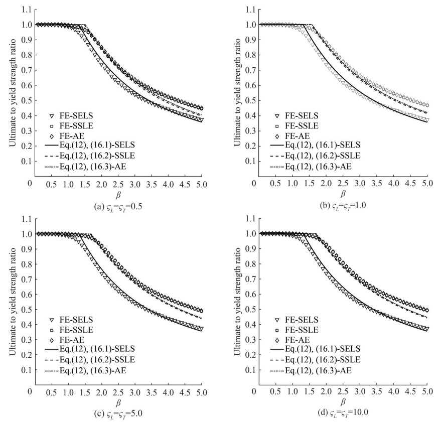 Figure 7 Ultimate to yield strength ratios-platings with edges elastically restrained against torsion (α=4.0)
6 Discussion
The effectiveness of the design formulas for the elastic buckling coefficient of platings with edges elastically restrained against torsion, combined with the ultimate strength equation provided by the International Standard DIN18800-3 "Steel Structures-Part 3: Stability-Safety against buckling of plates" (DIN, 1990) and the Recommended Practice RP-C201 "Buckling strength of plated structures" (DnV, 2023), is further checked in Figures 8(a)~(d). This equation has been selected as basis for comparison, provided that it is generally superior as regards the other ultimate strength formulas outlined in Subsection 2.2, as also proved by the comparative analysis with the FE results carried out in Subsection 3.5.
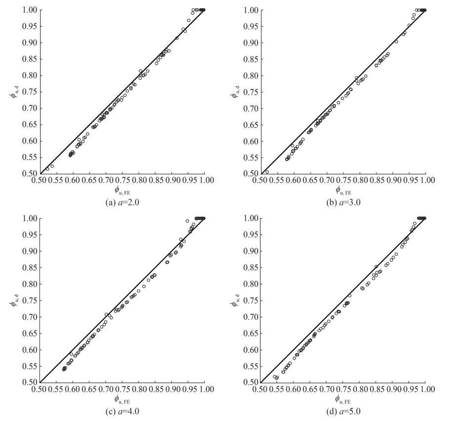 Figure 8 Check of design formulas against FE values
In this respect, four values of the aspect ratio are selected in the range from 2 to 5. The slenderness ratio is randomly varied from 1 to 4 to cover the entire design space of ship platings. The torsional stiffness ratios of longitudinal stiffeners and transverse primary supporting members are randomly varied in the range from 0 to 10, according to the typical scantlings of bulk carriers and oil tankers. Each graph provides the design values of the ultimate to yield strength ratio ϕu, d, obtained Eq. (12) and (16.3), against the relevant FE values ϕu, FE. In this respect, 100 FE simulations are carried out for each value of the aspect ratio, by randomly varying the slenderness parameter and the torsional stiffness ratios of short and long edges, to obtain a robust statistical analysis of the new design equations. A very good agreement is recognized in the entire design space of ship platings, as it can be gathered by Table 4 that provides the main statistical parameters, obtained by the comparative analysis of the design values against the FE ones. By Table 4 it is gathered that the new buckling formulas for platings with edges elastically restrained against torsion are accurate for practical design purposes and are slightly on the safe side, with a mean value of the ratio ϕu, d/ϕu, FE equal to about 0.98, independently of the plate panel aspect ratio. Besides, the coefficient of variation of the four data sets is equal to about 2%, which implies that the new design formulas are effective in the entire design space of ship platings and supporting members.
Table 4 Statistical analysis of the new design formulasStatistical parameters α=2.0 α=3.0 α=4.0 α=5.0 E [ϕu, d/ϕu, FE ] 0.982 7 0.981 7 0.981 9 0.977 8 Std [ϕu, d/ϕu, FE ] 0.020 8 0.019 4 0.023 1 0.022 2 cov[ϕu, d/ϕu, FE ] 0.021 2 0.019 7 0.023 6 0.022 7 In order to further verify the effectiveness of the proposed formulas for platings with edges elastically restrained against torsion, a comparative analysis with the Rule equations, provided by the "Common Structural Rules for Bulk Carriers and Oil Tankers" (IACS, 2022) and the Recommended Practice RP-C201 "Buckling strength of plated structures" (DnV, 2023), is carried out. In this respect, it must be preliminarily pointed out that the "Common Structural Rules for Bulk Carriers and Oil Tankers" (IACS, 2022) allow accounting for the torsional stiffness of longitudinal supporting members by a corrective factor, depending on the stiffener type and on the web to plating thickness ratio. As concerns the ultimate strength assessment, the ultimate to yield strength ratio of platings under uniaxial compression is determined by Eq. (10) according to the "Common Structural Rules for Bulk Carriers and Oil Tankers" (IACS, 2022) and by Eq. (12) in compliance with the Recommended Practice RP-C201 "Buckling strength of plated structures" (DnV, 2023). Table 5 reports the results of the comparative analysis, focusing on a set of reference platings of bulk carriers, oil tankers and containerships. The elastic buckling coefficient kxIACS, determined according to the "Common Structural Rules for Bulk Carriers and Oil Tankers" (IACS, 2022) and the relevant one kxSSLE obtained by the new Eq. (16.2) are provided in order to subsequently evaluate the ultimate to yield strength ratio and compare the relevant results with the FE values, obtained by Ansys APDL.
Table 5 Comparative analysis with Rule equationsb (mm) t (mm) σy (MPa) bw (mm) tw (mm) bf (mm) tf (mm) Stiffener type kxIACS kxSSLE Eq. (10)* Eq. (12)** Eq. (12)*** FE 850 15 315 250 12 90 16 Angle-bar 4.819 4.737 0.843 0.746 0.742 0.733 850 24 355 300 11 90 16 Angle-bar 4.154 4.213 1.000 0.936 0.939 0.914 875 26 355 350 13 150 22 Tee-section 4.150 4.457 1.000 0.963 0.982 0.947 830 20 315 550 12 150 25 Tee-section 4.259 5.100 1.000 0.887 0.938 0.931 830 18 315 550 12 150 25 Tee-section 4.356 5.328 0.942 0.834 0.891 0.892 830 20 315 300 13 90 17 Angle-bar 4.439 4.486 1.000 0.899 0.902 0.883 880 15 315 350 12 100 17 Angle-bar 4.819 4.903 0.822 0.727 0.732 0.727 880 14 315 300 13 90 17 Angle-bar 5.281 5.042 0.808 0.715 0.702 0.704 880 38 355 300 38 ‒ ‒ Flat bar 4.400 4.854 1.000 1.000 1.000 0.994 Notes: * Ultimate to yield strength ratio and elastic buckling coefficient according to the "Common Structural Rules for Bulk Carriers and Oil Tankers" (IACS, 2022); ** Ultimate to yield strength ratio according to the Recommended Practice RP-C201 "Buckling strength of plated structures" (DnV, 2023) and elastic buckling coefficient according to the "Common Structural Rules for Bulk Carriers and Oil Tankers" (IACS, 2022); *** Ultimate to yield strength ratio according to the Recommended Practice RP-C201 "Buckling strength of plated structures" (DnV, 2023) and elastic buckling coefficient according to Eq. (16.2) By the comparative analysis, it can be gathered that the ultimate strength formula provided by Eq. (12) and endorsed in the Recommended Practice RP-C201 "Buckling strength of plated structures" (DnV, 2023) is generally slightly conservative, as regards the IACS one provided by Eq. (10). Besides, the correction of the elastic buckling coefficient provided by Eq. (16.2) seems to be very effective, with a mean percentage error equal to 1.35% as regards the FE values. Current results confirm not only that longitudinal stiffeners increase the ultimate capacity of ship platings as predictable, but also that the ultimate to yield strength ratio formula, obtained by combining Eq. (12) and (16.2), is very reliable for practical design purposes.
7 Conclusions
The paper focused on the ultimate strength of platings with short and/or long edges elastically restrained against torsion. After a brief historical review about the main advances in the field of elastic buckling and ultimate strength analysis of platings under compression, some preliminary remarks, required to perform the eigenvalue buckling analysis and the ultimate nonlinear FE simulations, are provided. Two benchmark studies have been subsequently performed. The former focused on the eigenvalue buckling analysis of platings with edges elastically restrained against torsion, with the main aim of developing new design formulas for the relevant elastic buckling coefficients. The latter investigated the ultimate capacity of platings under uniaxial compression, accounting for the torsional stiffness of longitudinal stiffeners and transverse primary supporting members. Finally, the effectiveness of the new design formulas was further checked against a wide number of FE simulations. Based on current results, the following main outcomes have been achieved:
(ⅰ) The new elastic buckling formulas for platings with short, long and all edges elastically restrained against torsion are accurate for practical design purposes in the entire design space of ship platings and supporting members. These equations also fulfil the limit condition for platings with clamped edges.
(ⅱ) The design equation for the ultimate strength of platings under compression can be extended to platings with edges elastically restrained against torsion, after replacing the buckling coefficient for simply supported platings.
(ⅲ) The new elastic buckling equations for platings with edges elastically restrained against torsion are very accurate for the design against buckling of ship platings in the entire design space of plate panels and relevant supporting members.
Based on current results, the torsional stiffness of supporting members can be included in the ultimate strength check of isolated plate panels. These results are encouraging for further research activities, devoted to investigating the incidence of the torsional stiffness of supporting members on the ultimate capacity of platings under biaxial compression and shear. These topics will be the subject of future works.
Nomenclature a Plate length b Plate breadth C Coefficient of von Kármán equation D Bending stiffness of the plate panel E Young modulus G Coulomb modulus JL Torsional constant of longitudinal stiffeners JT Torsional constant of transverse supportingmembers kx Elastic buckling coefficient m Number of half waves in the longitudinal direction ny Number of mesh division in the transverse direction w Initial displacement field wmax Maximum amplitude of the initial displacement field α Plate panel aspect ratio β Slenderness parameter of the plate panel ςL Torsional stiffness ratio of longitudinal stiffeners ςT Torsional stiffness ratio of transverse supporting members λ Reference degree of slenderness of the plate panel ν Poisson modulus ϕu Ultimate to yield strength ratio ψ Edge stress ratio AC All edges clamped AE All edges elastically restrained against torsion AS All edges simply supported COV Coefficient of Variation FE Finite Element Analysis IACS International Association of Classification Societies SCLS Short (long) edges clamped (simply supported) SELS Short (long) edges elastically restrained (simply supported) SELS SSLC SSLE Short (long) edges simply supported (elastically restrained) UR Unified Requirement Appendix A
The nondimensional weighting functions, reported in the work by Paik and Thayamballi (2000), for the elastic buckling coefficients of simply supported platings with short edges elastically restrained against torsion are provided by Eq. from (A.1) to (A.5). Besides, the following conditions shall be fulfilled when evaluating the elastic buckling coefficient kxSELS by Eq. (3): (ⅰ) if 4.0 < α ≤ 4.5 and ςT > 0.2, then ςT=0.2; (ⅱ) if α > 4.5 and ςT > 0.1, then ςT=0.1; (ⅲ) if α ≥ 2.2 and ςT > 0.4, then ςT=0.4; (ⅳ) if α ≥ 1.5 and ςT > 1.4, then ςT=1.4; (v) if 8.0 < α ≤ 20.0, then ςT=8; (ⅵ) if α ≥ 5.0, then α=50:
$$ f_{0}(\alpha)=\left\{\begin{array}{l} 4.00 \text { for } 0 \leqslant \varsigma_{T}<0.4 \\ -0.001 \alpha^{4}+0.033 \alpha^{3}-0.241 \alpha^{2}+0.684 \alpha \\ \;\;\;\;\;\;\;\;\;\;\;\;\;\;\;+3.539 \text { for } 0.4 \leqslant \varsigma_{T}<0.8 \\ -0.148 \alpha^{2}+0.596 \alpha+3.847 \text { for } 0.8 \leqslant \varsigma_{T}<2 \\ -1.822 \alpha+7.850 \text { for } 2 \leqslant \varsigma_{T}<20 \\ 0.041 \alpha^{4}-0.602 \alpha^{3}+3.303 \alpha^{2}-8.176 \alpha \\ \;\;\;\;\;\;\;\;\;\;\;\;\;\;\;+12.144 \text { for } \varsigma_{T} \geqslant 20 \end{array}\right. $$ (A.1) $$ f_1(\alpha)=\left\{\begin{array}{l} 0.004 \alpha^4-0.007 \alpha^3-0.243 \alpha^2+0.630 \alpha \\ \;\;\;\;\;\;\;\;\;\;\;\;\;\;\;+3.617 \text { for } 0 \leqslant \varsigma_T<0.4 \\ -0.021 \alpha^4+0.184 \alpha^3-0.126 \alpha^2-2.625 \alpha \\ \;\;\;\;\;\;\;\;\;\;\;\;\;\;\;+6.457 \text { for } 0.4 \leqslant \varsigma_T<0.8 \\ 0.822 \alpha^2-4.516 \alpha+6.304 \text { for } 0.8 \leqslant \varsigma_T<2 \\ -0.106 \alpha+0.176 \text { for } 2 \leqslant \varsigma_T<20 \\ 0 \text { for } \varsigma_T \geqslant 20 \end{array}\right. $$ (A.2) $$ f_2(\alpha)=\left\{\begin{array}{l} -0.190 \alpha^4+2.093 \alpha^3-5.891 \alpha^2-2.096 \alpha \\ \;\;\;\;\;\;\;\;\;\;\;\;\;\;\;+1.792 \text { for } 0 \leqslant \varsigma_T<0.4 \\ 0.114 \alpha^4-1.412 \alpha^3+5.933 \alpha^2-8.638 \alpha \\ \;\;\;\;\;\;\;\;\;\;\;\;\;\;\;+0.224 \text { for } 0.4 \leqslant \varsigma_T<0.8 \\ -0.457 \alpha^2+2.571 \alpha-3.712 \text { for } 0.8 \leqslant \varsigma_T<2 \\ 0 \text { for } \varsigma_T \geqslant 2 \end{array}\right. $$ (A.3) $$ f_3(\alpha)=\left\{\begin{array}{l} 0.881 \alpha^4-10.851 \alpha^3+41.688 \alpha^2-43.150 \alpha \\ \;\;\;\;\;\;\;\;\;\;\;\;\;\;\;+14.615 \text { for } 0 \leqslant \varsigma_T<0.4 \\ -0.123 \alpha^4+1.549 \alpha^3-6.788 \alpha^2+11.299 \alpha \\ \;\;\;\;\;\;\;\;\;\;\;\;\;\;\;-3.662 \text { for } 0.4 \leqslant \varsigma_T<0.8 \\ 0.138 \alpha^2-0.793 \alpha+1.171 \text { for } 0.8 \leqslant \varsigma_T<2 \\ 0 \text { for } \varsigma_T \geqslant 2 \end{array}\right. $$ (A.4) $$ f_4(\alpha)=\left\{\begin{array}{l} -1.010 \alpha^4+12.827 \alpha^3-52.553 \alpha^2+67.072 \alpha \\ \;\;\;\;\;\;\;\;\;\;\;\;\;\;\;-27.585 \text { for } 0 \leqslant \varsigma_T<0.4 \\ 0.047 \alpha^4-0.586 \alpha^3+2.576 \alpha^2-4.410 \alpha \\ \;\;\;\;\;\;\;\;\;\;\;\;\;\;\;+1.748 \text { for } 0.4 \leqslant \varsigma_T<0.8 \\ -0.017 \alpha^2+0.099 \alpha-0.150 \text { for } 0.8 \leqslant \varsigma_T<2 \\ 0 \text { for } \varsigma_T \geqslant 2 \end{array}\right. $$ (A.5) Appendix B
The elastic buckling coefficients for platings with clamped edges are listed in Table B.1. Tables B.2, B.3 and B.4 that provide the relevant values for platings with short, long and all edges elastically restrained against torsion, respectively. Reference is made to the list of symbols and acronyms.
B1 Elastic buckling coefficients of platings with clamped edgesα SCLS SSLC AC FE analysis Eq. (15.1) FE analysis Eq. (15.2) FE analysis Eq. (15.3) 1.0 6.759 7.000 7.719 7.000 10.100 10.000 1.5 5.380 5.333 7.135 7.000 8.359 8.333 2.0 4.853 4.750 6.989 7.000 7.878 7.750 2.5 4.528 4.480 7.019 7.000 7.584 7.480 3.0 4.411 4.333 7.073 7.000 7.367 7.333 3.5 4.283 4.245 7.018 7.000 7.269 7.245 4.0 4.240 4.188 6.989 7.000 7.215 7.188 4.5 4.177 4.148 6.996 7.000 7.168 7.148 5.0 4.154 4.120 7.016 7.000 7.113 7.120 B2 Elastic buckling coefficients of platings with short edges elastically restrained against torsionα ςT=0.5 ςT=1.0 ςT=5.0 ςT=10.0 FE analysis Eq. (16.1) FE analysis Eq. (16.1) FE analysis Eq. (16.1) FE analysis Eq. (16.1) 1.0 5.261 5.364 5.775 5.875 6.520 6.679 6.644 6.830 1.5 5.255 4.821 5.317 5.005 5.372 5.246 5.379 5.288 2.0 4.644 4.573 4.740 4.645 4.834 4.724 4.846 4.737 2.5 4.502 4.434 4.517 4.458 4.530 4.475 4.532 4.478 3.0 4.359 4.345 4.386 4.346 4.409 4.337 4.412 4.335 3.5 4.277 4.285 4.282 4.273 4.286 4.252 4.287 4.249 4.0 4.224 4.241 4.234 4.222 4.243 4.196 4.244 4.192 4.5 4.177 4.208 4.179 4.185 4.181 4.157 4.182 4.153 5.0 4.153 4.182 4.157 4.158 4.161 4.129 4.161 4.124 B3 Elastic buckling coefficients of platings with long edges elastically restrained against torsionα ςL=0.5 ςL=1.0 ςL=5.0 ςL=10.0 FE analysis Eq. (16.2) FE analysis Eq. (16.2) FE analysis Eq. (16.2) FE analysis Eq. (16.2) 1.0 5.414 5.364 6.169 5.875 7.624 6.679 7.670 6.830 1.5 5.520 5.364 6.001 5.875 6.800 6.679 6.957 6.830 2.0 5.414 5.364 6.168 5.875 6.759 6.679 6.868 6.830 2.5 5.404 5.364 5.976 5.875 6.832 6.679 6.921 6.830 3.0 5.414 5.364 6.002 5.875 6.800 6.679 6.957 6.830 3.5 5.380 5.364 6.000 5.875 6.751 6.679 6.877 6.830 4.0 5.414 5.364 5.973 5.875 6.759 6.679 6.868 6.830 4.5 5.376 5.364 6.002 5.875 6.791 6.679 6.889 6.830 5.0 5.403 5.364 5.976 5.875 6.757 6.679 6.892 6.830 B4 Elastic buckling coefficients of platings with all edges elastically restrained against torsionα ςT=ςL=0.5 ςT=ςL=1.0 ςT=ςL=5.0 ςT=ςL=10.0 FE analysis Eq. (16.3) FE analysis Eq. (16.3) FE analysis Eq. (16.3) FE analysis Eq. (16.3) 1.0 6.628 6.727 7.763 7.750 9.479 9.357 9.787 9.660 1.5 6.484 6.185 7.173 6.880 8.071 7.925 8.218 8.118 2.0 5.956 5.937 6.630 6.520 7.640 7.403 7.765 7.567 2.5 5.868 5.797 6.433 6.333 7.284 7.154 7.435 7.308 3.0 5.676 5.709 6.298 6.221 7.115 7.016 7.243 7.165 3.5 5.634 5.648 6.208 6.148 7.040 6.931 7.158 7.079 4.0 5.555 5.605 6.169 6.097 6.972 6.874 7.106 7.022 4.5 5.531 5.572 6.118 6.060 6.919 6.835 7.045 6.983 5.0 5.494 5.546 6.093 6.033 6.889 6.807 7.009 6.955 Appendix C
The ultimate to yield strength ratios of platings with edges are listed in Table C.1. Tables C.2, C.3 and C.4 that provide the relevant values for platings with short, long and all edges elastically restrained against torsion, respectively. Reference is made to the list of symbols and acronyms.
C1 Ultimate strength of platings with clamped edges (α=4.0)β SCLS SSLC AC FE analysis Eq. (12) and (15.1) FE analysis Eq. (12) and (15.2) FE analysis Eq. (12) and (15.3) 1.0 1.000 1.000 1.000 1.000 1.000 1.000 1.5 0.898 0.927 0.989 1.000 0.989 1.000 2.0 0.739 0.765 0.932 0.910 0.931 0.917 2.5 0.619 0.645 0.816 0.783 0.813 0.791 3.0 0.540 0.556 0.707 0.684 0.707 0.691 3.5 0.484 0.488 0.631 0.605 0.631 0.612 4.0 0.440 0.434 0.575 0.542 0.577 0.548 4.5 0.405 0.391 0.531 0.490 0.533 0.496 5.0 0.374 0.356 0.494 0.447 0.498 0.453 C2 Ultimate strength of platings with short edges elastically restrained against torsion (α=4.0)β ςT=0.5 ςT=1.0 ςT=5.0 ςT=10.0 FE analysis Eq. (12) and (16.1) FE analysis Eq. (12) and 16.1) FE analysis Eq. (12) and (16.1) FE analysis Eq. (12) and (16.1) 0 1.000 1.000 1.000 1.000 1.000 1.000 1.000 1.000 1.5 0.987 1.000 0.986 1.000 0.986 1.000 0.986 1.000 2.0 0.899 0.930 0.897 0.929 0.898 0.927 0.898 0.927 2.5 0.739 0.768 0.738 0.767 0.739 0.765 0.738 0.765 3.0 0.619 0.648 0.618 0.647 0.621 0.645 0.621 0.645 3.5 0.539 0.559 0.541 0.558 0.539 0.556 0.540 0.556 4.0 0.484 0.491 0.483 0.490 0.484 0.488 0.485 0.488 4.5 0.444 0.437 0.440 0.436 0.441 0.435 0.441 0.435 5.0 0.406 0.393 0.406 0.393 0.405 0.392 0.406 0.391 C3 Ultimate strength of platings with long edges elastically restrained against torsion (α=4.0)β ςL=0.5 ςL=1.0 ςL=5.0 ςL=10.0 FE analysis Eq. (12) and (16.2) FE analysis Eq. (12) and (16.2) FE analysis Eq. (12) and (16.2) FE analysis Eq. (12) and (16.2) 1.0 1.000 1.000 1.000 1.000 1.000 1.000 1.000 1.000 1.5 0.996 1.000 0.998 1.000 0.999 1.000 0.999 1.000 2.0 0.965 0.994 0.976 1.000 0.986 1.000 0.988 1.000 2.5 0.845 0.834 0.880 0.860 0.921 0.896 0.927 0.903 3.0 0.722 0.710 0.755 0.735 0.800 0.770 0.806 0.777 3.5 0.634 0.615 0.661 0.638 0.697 0.671 0.703 0.677 4.0 0.571 0.542 0.596 0.563 0.623 0.594 0.628 0.599 4.5 0.522 0.484 0.546 0.503 0.570 0.531 0.573 0.536 5.0 0.481 0.437 0.503 0.454 0.525 0.480 0.529 0.485 C4 Ultimate strength of platings with all edges elastically restrained against torsion (α=4.0)β ςL=ςT=0.5 ςL=ςT=1.0 ςL=ςT=5.0 ςL=ςT=10.0 FE analysis Eq. (12) and (16.3) FE analysis Eq. (12) and (16.3) FE analysis Eq. (12) and (16.3) FE analysis Eq. (12) and (16.3) 1.0 1.000 1.000 1.000 1.000 1.000 1.000 1.000 1.000 1.5 0.996 1.000 0.997 1.000 0.999 1.000 0.999 1.000 2.0 0.966 1.000 0.978 1.000 0.987 1.000 0.988 1.000 2.5 0.851 0.847 0.883 0.871 0.920 0.905 0.925 0.911 3.0 0.729 0.722 0.758 0.745 0.799 0.778 0.806 0.784 3.5 0.638 0.626 0.664 0.648 0.697 0.679 0.702 0.685 4.0 0.573 0.552 0.599 0.572 0.624 0.601 0.626 0.606 4.5 0.525 0.493 0.548 0.511 0.573 0.538 0.574 0.543 5.0 0.485 0.445 0.505 0.462 0.528 0.486 0.532 0.491 Competing interest The authors have no competing interests to declare that are relevant to the content of this article. -
Figure 1 Layout of the plate panel
Figure 2 Initial displacement field of simply supported plating under uniaxial compression
Figure 3 Eigenvalue and ultimate strength analysis-simply supported platings at all edges
Figure 4 Elastic buckling coefficients-platings with perfect boundary conditions
Figure 5 Elastic buckling coefficients-platings with edges elastically restrained against torsion
Figure 6 Ultimate to yield strength ratios-platings with perfect boundary conditions (α=4.0)
Figure 7 Ultimate to yield strength ratios-platings with edges elastically restrained against torsion (α=4.0)
Figure 8 Check of design formulas against FE values
Table 1 Convergence of solution-Ultimate to yield strength ratios of simply supported platings (α=3)
β Very coarse mesh Coarse mesh Fine mesh Very fine mesh ny=10 (300 elements) ny=20 (1 200 elements) ny=30 (2 700 elements) ny=40 (4 800 elements) 1.0 0.986 8 0.984 9 0.985 2 0.985 2 1.5 0.897 1 0.890 3 0.889 0 0.887 7 2.0 0.738 2 0.726 8 0.725 1 0.724 9 2.5 0.617 0 0.609 6 0.608 6 0.607 1 3.0 0.542 0 0.533 3 0.531 4 0.530 6 3.5 0.489 8 0.479 6 0.477 8 0.476 8 4.0 0.451 2 0.437 9 0.436 3 0.434 6 4.5 0.419 2 0.405 0 0.401 3 0.400 2 5.0 0.390 9 0.374 3 0.371 5 0.368 9 Table 2 Design space of plate panels
Plate aspect ratio, α 1.0‒5.0 Plate slenderness ratio, β 0.1‒5.0 Torsional constant of longitudinal stiffeners/transverse supporting members, ςL/ςT 0.5, 1.0, 5.0, 10.0 Table 3 Reference conditions of the benchmark study
Boundary condition Reference case Acronym Perfect Short edges clamped and long edges simply supported SCLS Short edges simply supported and long edges clamped SSLC All edges clamped AC Elastically restrained Short edges elastically retrained against torsion and long edges simply supported SELS Short edges simply supported and long edges elastically restrained against torsion SSLE All edges elastically restrained against torsion AE Table 4 Statistical analysis of the new design formulas
Statistical parameters α=2.0 α=3.0 α=4.0 α=5.0 E [ϕu, d/ϕu, FE ] 0.982 7 0.981 7 0.981 9 0.977 8 Std [ϕu, d/ϕu, FE ] 0.020 8 0.019 4 0.023 1 0.022 2 cov[ϕu, d/ϕu, FE ] 0.021 2 0.019 7 0.023 6 0.022 7 Table 5 Comparative analysis with Rule equations
b (mm) t (mm) σy (MPa) bw (mm) tw (mm) bf (mm) tf (mm) Stiffener type kxIACS kxSSLE Eq. (10)* Eq. (12)** Eq. (12)*** FE 850 15 315 250 12 90 16 Angle-bar 4.819 4.737 0.843 0.746 0.742 0.733 850 24 355 300 11 90 16 Angle-bar 4.154 4.213 1.000 0.936 0.939 0.914 875 26 355 350 13 150 22 Tee-section 4.150 4.457 1.000 0.963 0.982 0.947 830 20 315 550 12 150 25 Tee-section 4.259 5.100 1.000 0.887 0.938 0.931 830 18 315 550 12 150 25 Tee-section 4.356 5.328 0.942 0.834 0.891 0.892 830 20 315 300 13 90 17 Angle-bar 4.439 4.486 1.000 0.899 0.902 0.883 880 15 315 350 12 100 17 Angle-bar 4.819 4.903 0.822 0.727 0.732 0.727 880 14 315 300 13 90 17 Angle-bar 5.281 5.042 0.808 0.715 0.702 0.704 880 38 355 300 38 ‒ ‒ Flat bar 4.400 4.854 1.000 1.000 1.000 0.994 Notes: * Ultimate to yield strength ratio and elastic buckling coefficient according to the "Common Structural Rules for Bulk Carriers and Oil Tankers" (IACS, 2022); ** Ultimate to yield strength ratio according to the Recommended Practice RP-C201 "Buckling strength of plated structures" (DnV, 2023) and elastic buckling coefficient according to the "Common Structural Rules for Bulk Carriers and Oil Tankers" (IACS, 2022); *** Ultimate to yield strength ratio according to the Recommended Practice RP-C201 "Buckling strength of plated structures" (DnV, 2023) and elastic buckling coefficient according to Eq. (16.2) Nomenclature a Plate length b Plate breadth C Coefficient of von Kármán equation D Bending stiffness of the plate panel E Young modulus G Coulomb modulus JL Torsional constant of longitudinal stiffeners JT Torsional constant of transverse supportingmembers kx Elastic buckling coefficient m Number of half waves in the longitudinal direction ny Number of mesh division in the transverse direction w Initial displacement field wmax Maximum amplitude of the initial displacement field α Plate panel aspect ratio β Slenderness parameter of the plate panel ςL Torsional stiffness ratio of longitudinal stiffeners ςT Torsional stiffness ratio of transverse supporting members λ Reference degree of slenderness of the plate panel ν Poisson modulus ϕu Ultimate to yield strength ratio ψ Edge stress ratio AC All edges clamped AE All edges elastically restrained against torsion AS All edges simply supported COV Coefficient of Variation FE Finite Element Analysis IACS International Association of Classification Societies SCLS Short (long) edges clamped (simply supported) SELS Short (long) edges elastically restrained (simply supported) SELS SSLC SSLE Short (long) edges simply supported (elastically restrained) UR Unified Requirement B1 Elastic buckling coefficients of platings with clamped edges
α SCLS SSLC AC FE analysis Eq. (15.1) FE analysis Eq. (15.2) FE analysis Eq. (15.3) 1.0 6.759 7.000 7.719 7.000 10.100 10.000 1.5 5.380 5.333 7.135 7.000 8.359 8.333 2.0 4.853 4.750 6.989 7.000 7.878 7.750 2.5 4.528 4.480 7.019 7.000 7.584 7.480 3.0 4.411 4.333 7.073 7.000 7.367 7.333 3.5 4.283 4.245 7.018 7.000 7.269 7.245 4.0 4.240 4.188 6.989 7.000 7.215 7.188 4.5 4.177 4.148 6.996 7.000 7.168 7.148 5.0 4.154 4.120 7.016 7.000 7.113 7.120 B2 Elastic buckling coefficients of platings with short edges elastically restrained against torsion
α ςT=0.5 ςT=1.0 ςT=5.0 ςT=10.0 FE analysis Eq. (16.1) FE analysis Eq. (16.1) FE analysis Eq. (16.1) FE analysis Eq. (16.1) 1.0 5.261 5.364 5.775 5.875 6.520 6.679 6.644 6.830 1.5 5.255 4.821 5.317 5.005 5.372 5.246 5.379 5.288 2.0 4.644 4.573 4.740 4.645 4.834 4.724 4.846 4.737 2.5 4.502 4.434 4.517 4.458 4.530 4.475 4.532 4.478 3.0 4.359 4.345 4.386 4.346 4.409 4.337 4.412 4.335 3.5 4.277 4.285 4.282 4.273 4.286 4.252 4.287 4.249 4.0 4.224 4.241 4.234 4.222 4.243 4.196 4.244 4.192 4.5 4.177 4.208 4.179 4.185 4.181 4.157 4.182 4.153 5.0 4.153 4.182 4.157 4.158 4.161 4.129 4.161 4.124 B3 Elastic buckling coefficients of platings with long edges elastically restrained against torsion
α ςL=0.5 ςL=1.0 ςL=5.0 ςL=10.0 FE analysis Eq. (16.2) FE analysis Eq. (16.2) FE analysis Eq. (16.2) FE analysis Eq. (16.2) 1.0 5.414 5.364 6.169 5.875 7.624 6.679 7.670 6.830 1.5 5.520 5.364 6.001 5.875 6.800 6.679 6.957 6.830 2.0 5.414 5.364 6.168 5.875 6.759 6.679 6.868 6.830 2.5 5.404 5.364 5.976 5.875 6.832 6.679 6.921 6.830 3.0 5.414 5.364 6.002 5.875 6.800 6.679 6.957 6.830 3.5 5.380 5.364 6.000 5.875 6.751 6.679 6.877 6.830 4.0 5.414 5.364 5.973 5.875 6.759 6.679 6.868 6.830 4.5 5.376 5.364 6.002 5.875 6.791 6.679 6.889 6.830 5.0 5.403 5.364 5.976 5.875 6.757 6.679 6.892 6.830 B4 Elastic buckling coefficients of platings with all edges elastically restrained against torsion
α ςT=ςL=0.5 ςT=ςL=1.0 ςT=ςL=5.0 ςT=ςL=10.0 FE analysis Eq. (16.3) FE analysis Eq. (16.3) FE analysis Eq. (16.3) FE analysis Eq. (16.3) 1.0 6.628 6.727 7.763 7.750 9.479 9.357 9.787 9.660 1.5 6.484 6.185 7.173 6.880 8.071 7.925 8.218 8.118 2.0 5.956 5.937 6.630 6.520 7.640 7.403 7.765 7.567 2.5 5.868 5.797 6.433 6.333 7.284 7.154 7.435 7.308 3.0 5.676 5.709 6.298 6.221 7.115 7.016 7.243 7.165 3.5 5.634 5.648 6.208 6.148 7.040 6.931 7.158 7.079 4.0 5.555 5.605 6.169 6.097 6.972 6.874 7.106 7.022 4.5 5.531 5.572 6.118 6.060 6.919 6.835 7.045 6.983 5.0 5.494 5.546 6.093 6.033 6.889 6.807 7.009 6.955 C1 Ultimate strength of platings with clamped edges (α=4.0)
β SCLS SSLC AC FE analysis Eq. (12) and (15.1) FE analysis Eq. (12) and (15.2) FE analysis Eq. (12) and (15.3) 1.0 1.000 1.000 1.000 1.000 1.000 1.000 1.5 0.898 0.927 0.989 1.000 0.989 1.000 2.0 0.739 0.765 0.932 0.910 0.931 0.917 2.5 0.619 0.645 0.816 0.783 0.813 0.791 3.0 0.540 0.556 0.707 0.684 0.707 0.691 3.5 0.484 0.488 0.631 0.605 0.631 0.612 4.0 0.440 0.434 0.575 0.542 0.577 0.548 4.5 0.405 0.391 0.531 0.490 0.533 0.496 5.0 0.374 0.356 0.494 0.447 0.498 0.453 C2 Ultimate strength of platings with short edges elastically restrained against torsion (α=4.0)
β ςT=0.5 ςT=1.0 ςT=5.0 ςT=10.0 FE analysis Eq. (12) and (16.1) FE analysis Eq. (12) and 16.1) FE analysis Eq. (12) and (16.1) FE analysis Eq. (12) and (16.1) 0 1.000 1.000 1.000 1.000 1.000 1.000 1.000 1.000 1.5 0.987 1.000 0.986 1.000 0.986 1.000 0.986 1.000 2.0 0.899 0.930 0.897 0.929 0.898 0.927 0.898 0.927 2.5 0.739 0.768 0.738 0.767 0.739 0.765 0.738 0.765 3.0 0.619 0.648 0.618 0.647 0.621 0.645 0.621 0.645 3.5 0.539 0.559 0.541 0.558 0.539 0.556 0.540 0.556 4.0 0.484 0.491 0.483 0.490 0.484 0.488 0.485 0.488 4.5 0.444 0.437 0.440 0.436 0.441 0.435 0.441 0.435 5.0 0.406 0.393 0.406 0.393 0.405 0.392 0.406 0.391 C3 Ultimate strength of platings with long edges elastically restrained against torsion (α=4.0)
β ςL=0.5 ςL=1.0 ςL=5.0 ςL=10.0 FE analysis Eq. (12) and (16.2) FE analysis Eq. (12) and (16.2) FE analysis Eq. (12) and (16.2) FE analysis Eq. (12) and (16.2) 1.0 1.000 1.000 1.000 1.000 1.000 1.000 1.000 1.000 1.5 0.996 1.000 0.998 1.000 0.999 1.000 0.999 1.000 2.0 0.965 0.994 0.976 1.000 0.986 1.000 0.988 1.000 2.5 0.845 0.834 0.880 0.860 0.921 0.896 0.927 0.903 3.0 0.722 0.710 0.755 0.735 0.800 0.770 0.806 0.777 3.5 0.634 0.615 0.661 0.638 0.697 0.671 0.703 0.677 4.0 0.571 0.542 0.596 0.563 0.623 0.594 0.628 0.599 4.5 0.522 0.484 0.546 0.503 0.570 0.531 0.573 0.536 5.0 0.481 0.437 0.503 0.454 0.525 0.480 0.529 0.485 C4 Ultimate strength of platings with all edges elastically restrained against torsion (α=4.0)
β ςL=ςT=0.5 ςL=ςT=1.0 ςL=ςT=5.0 ςL=ςT=10.0 FE analysis Eq. (12) and (16.3) FE analysis Eq. (12) and (16.3) FE analysis Eq. (12) and (16.3) FE analysis Eq. (12) and (16.3) 1.0 1.000 1.000 1.000 1.000 1.000 1.000 1.000 1.000 1.5 0.996 1.000 0.997 1.000 0.999 1.000 0.999 1.000 2.0 0.966 1.000 0.978 1.000 0.987 1.000 0.988 1.000 2.5 0.851 0.847 0.883 0.871 0.920 0.905 0.925 0.911 3.0 0.729 0.722 0.758 0.745 0.799 0.778 0.806 0.784 3.5 0.638 0.626 0.664 0.648 0.697 0.679 0.702 0.685 4.0 0.573 0.552 0.599 0.572 0.624 0.601 0.626 0.606 4.5 0.525 0.493 0.548 0.511 0.573 0.538 0.574 0.543 5.0 0.485 0.445 0.505 0.462 0.528 0.486 0.532 0.491 -
Allen HG, Bulson PS (1980) Background to buckling. New York: McGraw-Hill Book Company, US Ansys (2022) ANSYS User Guide Bridget FJ, Gerome CC, Vosseller AB (1934) Some new experiments on buckling of thin-wall construction. Transactions of the American Society of Mechanical Engineers 56(6): 569–578 https://doi.org/10.1115/1.4019813 Bryan GH (1890) On the stability of a plane plate under thrusts in its own plane, with applications to the "buckling" of the sides of a ship. Proceedings of the London Mathematical Society 22(1): 54–67 https://doi.org/10.1112/plms/s1-22.1.54 Caldwell JB (1965) Ultimate longitudinal strength. Transactions of the Royal Institution of Naval Architects 107: 411–430 Conley WF, Becker LA, Allnutt RB (1963) Buckling and ultimate strength of plating loaded in edge compression. Progress Report 2-Unstiffened panels. David Taylor Model Basin Report 1682 Cui W, Wang Y, Pedersen PT (2002) Strength of ship plates under combined loading. Marine Structures 15, 75–97. https://doi.org/10.1016/S0951-8339(01)00009-0 DIN (1990) DIN 18800-3 "Steel Structures-Part 3: Stability-Safety against buckling of plates". Deutsches Institut fur Normung E.V., Berlin, Germany DnV (2023) Recommended Practice RP-C201 "Buckling strength of plated structures". Det Norske Veritas, Oslo, Norway ECS (2019) ENV 1993-1-5 "Eurocode 3: Design of steel structures-Part 1–5: General rules-Supplementary rules for planar plated structures without transverse loading". The European Committee for Standardization, Brussels, Belgium Evans JH (1960) Strength of wide plates under uniform edge compression. The Society of Naval Architects and Marine Engineers Transactions 68: 585–621 Faulkner D (1975) A review of effective plating for the analysis of stiffened plating in bending and compression. Journal of Ship Research 19(1): 1–17. https://doi.org/10.5957/jsr.1975.19.L1 Feng L, Hu L, Chen X, Shi H (2020) A parametric study on effects of pitting corrosion on stiffened panels' ultimate strength. International Journal of Naval Architecture and Ocean Engineering 12: 699–710. https://doi.org/10.1016/j.ijnaoe.2020.08.001 Frankland JM (1940) The strength of ship plating under edge compression. Technical report, United States Experimental Model Basin, Washington, DC, Report n. 469 Fujikubo M, Yao T (1999) Elastic local buckling strength of stiffened plate considering plate/stiffener interaction and welding residual stress. Marine Structures 12, 543–564. https://doi.org/10.1016/S0951-8339(99)00032-5 Guedes Soares C, Kmiecik M (1993) Simulation of the ultimate compressive strength of unstiffened rectangular plates. Marine Structures 6(5–6): 553–569. https://doi.org/10.1016/0951-8339(93)90037-4 Guedes Soares C, Gordo JM (1996a) Collapse strength of rectangular plates under transverse compression. Journal of Constructional Steel Research 36(3), 215–234. https://doi.org/10.1016/0143-974X(95)00018-Q Guedes Soares C, Gordo JM (1996b) Compressive strength of rectangular plates under biaxial load and lateral pressure. Thin-Walled Structures 24(3), 231–259. https://doi.org/10.1016/0263-8231(95)00030-5 IACS (2006a) Common Structural Rules for Bulk Carriers. The International Association of Classification Societies, London, UK IACS (2006b) Common Structural Rules for Oil Tankers. The International Association of Classification Societies, London, UK IACS (2022). Common Structural Rules for Bulk Carriers and Oil Tankers. The International Association of Classification Societies, London, UK IACS (2023) New Unified Requirement On Buckling Strength Assessment of Ship Structural Elements (UR S35). The International Association of Classification Societies, London, UK Khan I, Zhang S (2011) Effects of welding-induced residual stress on ultimate strength of plates and stiffened panels. Ships and Offshore Structures 6(4): 297–309. https://doi.org/10.1080/17445301003776209 Lundquist EE, Stowell EZ (1942) Critical Compressive Stress for Flat Rectangular Plates Supported Along All Edges and Elastically Restrained Against Rotation along the Unloaded Edges. NACA Technical Report n. 733 Masaoka K, Mansour A (2004) Ultimate compressive strength of imperfect unstiffened plates: simple design equations. Journal of Ship Research 48(3): 191–201. https://doi.org/10.5957/jsr.2004.483.191 McKenzie KI (1964) The Buckling of a Rectangular Plate under Combined Biaxial Compression, Bending and Shear. Aeronautical Quarterly 15(3): 239–246. https://doi.org/10.1017/S0001925900010866 Paik JK, Thayamballi AK (2000) Buckling strength of steel plating with elastically restrained edges. Thin-Walled Structures 37, 27–55. https://doi.org/10.1016/S0263-8231(00)00009-4 Paik JK, Thayamballi AK, Lee JM (2004) Effect of initial deflection shape on the ultimate strength behavior of welded steel plates under biaxial compressive loads. Journal of Ship Research 48(1): 45–60. https://doi.org/10.5957/jsr.2004.48.L45 Piscopo V (2012) Buckling of uniaxially compressed plates with all edges elastically restrained against torsion. International Journal of Advanced Computer Science 2(6): 242–249 Piscopo V, Scamardella A (2018) Towards a unified formulation for the ultimate strength assessment of uncorroded and pitted platings under uniaxial compression. Ocean Engineering 169: 70–86. https://doi.org/10.1016/j.oceaneng.2018.08.042 Piscopo V, Scamardella A (2019) Comparative study between analytical and FE analysis for the ultimate strength assessment of pitted platings. International Shipbuilding Progress 66(1), 3–15. https://doi.org/10.3233/ISP-180251 Piscopo V, Scamardella A (2020) Ultimate strength assessment of intact and pitted platings under biaxial compression. Engineering Structures 204, 11079, 1–17. https://doi.org/10.1016/j.engstruct.2019.110079 Piscopo V, Scamardella A (2021) Incidence of Pitting Corrosion Wastage on the Hull Girder Ultimate Strength. Journal of Marine Science and Application 20(3): 477–490. https://doi.org/10.1007/s11804-021-00218-x Roettinger I (1947) A generalization of the finite Fourier transformation and applications. Quarterly of Applied Mathematics 5(3): 298–319 https://doi.org/10.1090/qam/21987 Scheer J, Peil U, Fuchs G (1987) Auswertung von internationalen Veröffentlichungen, Versuchsberichten, Kommissionspapieren u. ä. auf dem Gebiet des Beulens von Platten aus Stahl (in German). Technical report, Institutes für Stahlbau, Technische Universität Braunschweig, Braunschweig, Germany, Report 6095 Strandhagen AG (1944) Use of sine transform for non-simply supported beams. Quarterly of Applied Mathematics 1(4): 346–348 https://doi.org/10.1090/qam/9409 Timoshenko SP (1910) Einige stabilitätsprobleme der elastizitätstheorie. Zeitschrift für Mathematik und Physik 58(4): 337–357 Timoshenko SP, Gere JM (1961) Theory of Elastic Stability 2nd edition, McGraw-Hill Book Company, New York, US Ueda Y, Yao T (1985) The influence of complex initial deflection on the behaviour and ultimate strength of rectangular plates in compression. Journal of Constructional Steel Research 5(4): 265–302. https://doi.org/10.1016/0143-974X(85)90024-0 Von Kármán T, Sechler EE, Donnell LH (1932) The strength of thin plates in compression. Transactions of the American Society of Mechanical Engineers 54: 53–57 https://doi.org/10.1115/1.4021738 Wang R, Shenoi RA, Sobey A (2018) Ultimate strength assessment of plated steel structures with random pitting corrosion damage. Journal of Constructional Steel Research 143: 331–342. https://doi.org/10.1016/jjcsr.2018.01.014 Winter G (1947) Strength of thin steel compression flanges. Transactions of the American Society of Civil Engineers 112(1): 339–387 https://doi.org/10.1061/TACEAT.0006092 Yi MS, Noh SH, Lee DH, Seo DH, Paik JK (2021) Direct measurements, numerical predictions and simple formula estimations of welding-induced biaxial residual stresses in a full-scale steel stiffened plate structure. Structures 29, 2094–2105. https://doi.org/10.1016/j.istruc.2020.05.030 Zhang S (2016) A review and study on ultimate strength of steel plates and stiffened panels in axial compression. Ships and Offshore Structures 11(1): 81–91. https://doi.org/10.1080/17445302.2014.992610
