
Influence of Length to Diameter Ratio of the Skirt on Horizontal Bearing Characteristics of Tripod Suction Jacket Foundation in Sandy Soil
https://doi.org/10.1007/s11804-024-00411-8
-
Abstract
The tripod foundation (TF) is a prevalent foundation configuration in contemporary engineering practices. In comparison to a single pile,TF comprised interconnected individual piles,resulting in enhanced bearing capacity and stability. A physical model test was conducted within a sandy soil foundation,systematically varying the length-to-diameter ratio of the TF. The investigation aimed to comprehend the impact of altering the height of the central bucket on the historical horizontal bearing capacity of the foundation in saturated sand. Additionally,the study scrutinized the historical consequences of soil pressure and pore water pressure surrounding the bucket throughout the loading process. The historical findings revealed a significant enhancement in the horizontal bearing capacity of the TF under undrained conditions. When subjected to a historical horizontal loading angle of 0° for a single pile,the multi-bucket foundation exhibited superior historical bearing capacity compared to a single-pile foundation experiencing a historical loading angle of 180° under pulling conditions. With each historical increment in bucket height from 150 mm to 350 mm in 100 mm intervals,the historical horizontal bearing capacity of the TF exhibited an approximately 75% increase relative to the 150 mm bucket height,indicating a proportional relationship. Importantly,the historical internal pore water pressure within the bucket foundation remained unaffected by drainage conditions during loading. Conversely,undrained conditions led to a historical elevation in pore water pressure at the lower side of the pressure bucket. Consequently,in practical engineering applications,the optimization of the historical bearing efficacy of the TF necessitated the historical closure of the valve atop the foundation to sustain internal negative pressure within the bucket. This historical measure served to augment the historical horizontal bearing capacity. Simultaneously,historical external loads,such as wind,waves,and currents,were directed towards any individual bucket within the TF for optimal historical performance.Article Highlights● This paper underscores the structural superiority of the tripod foundation (TF) over single piles, highlighting its increased stability and bearing capacity achieved through the interconnected arrangement of multiple single piles.● Through a comprehensive physical model test in sandy soil, the research yields valuable insights into the TF’s behavior, emphasizing the influence of the middle bucket’s height on horizontal bearing capacity and detailing the effects of soil and pore water pressure during loading.● The study demonstrates the significant enhancement of horizontal bearing capacity under undrained conditions, and suggests practical strategies for optimal TF performance, including maintaining a closed valve for internal negative pressure and addressing external environmental loads strategically. -
1 Introduction
The tripod foundation (TF), which is a typical foundation construction for offshore wind turbines (OWT), compensates for the drawbacks of conventional foundation structures such as single piles and gravity structures, which are costly and have little economic advantage. The features include its small weight, high stiffness, great mechanical performance, a broad range of usable water depths, little reliance on the land, and minimal wave interference.
The suction bucket foundation is a commonly used offshore wind pile foundation, which is divided into multibucket foundation and single-pile foundation. In terms of appearance, it is mostly an inverted large-diameter barrel with an open bottom end and a closed top. The foundation of the suction bucket uses its own gravity to sink to a certain position, and then the water in the bucket is pumped out by the suction pump to generate suction, and the pressure difference between inside and outside is used to press it into the seabed. A number of studies on the ultimate carrying capacity of horizontal, vertical, torque, and bending moments for suction bucket foundations have been conducted recently by academics (Mahmood, et al. 2020). The investigation has revealed that the incorporation of a skirted footing leads to an augmentation in bearing capacity accompanied by a reduction in settlement, thereby enhancing the load-settlement behavior of the footing. As the L/D ratio increases, the lines of failure beneath the footing intersect, demonstrating the presence of the skirted configuration. However, the influence of this configuration does not extend to the soil surface, resulting in the confinement of soil within the skirt. This confinement effect contributes to an elevation in bearing capacity. A model test was conducted to assess the horizontal bearing capacity of a bucket foundation in silt and sand. The analysis focused on evaluating the impact of foundation size and loading height on the bearing characteristics of the bucket foundation. The findings indicate that soil within the passive area of the bucket skirt significantly contributes to the horizontal bearing capacity of the foundation. Subsequently, a method for calculating bearing capacity was proposed based on the interaction mechanism observed in the study (Zhu, et al., 2014). In order to explore the vertical ultimate bearing capacity and failure process of bucket foundations under various diameters and buried depths, a three-dimensional model was generated through finite element software, and a calculation formula for vertical bearing capacity was presented (Yun and Bransby, 2007). The investigation involved subjecting a bucket foundation to horizontal pull-out loads at different loading sites and angles. This exploration led to the identification of three distinct failure mechanisms. Additionally, a mathematical technique was developed to ascertain the pull-out capacity of a bucket foundation under horizontal loads (Bang and Cho 2002; Bang, et al., 2011). Numerical simulation was utilized to determine the horizontal bearing capacity of bucket foundations in typically cemented clay without drainage. Upon the discovery that the length-to-diameter ratio serves as the primary controlling factor, a formula for the horizontal bearing capacity of bucket foundations was established (Hung and Kim, 2012). In the exploration of the vertical and horizontal ultimate bearing capacity of bucket foundations with diverse height-to-diameter ratios on homogeneous saturated soft clay, a thorough analysis was conducted using three-dimensional finite element (FE) analysis (Hung and Kim, 2014).
In investigating the horizontal bearing capacity of foundations in muddy clay, a large-scale model of the composite bucket foundation was developed. The research aimed to ascertain the limits of the composite bucket foundation under horizontal loads and to establish the governing law for the distribution of earth pressure (Liu, et al., 2016). The deduction was made that increasing the length-to-diameter ratio of the buckets contributes to an improvement in horizontal bearing capacity under various bucket spacings. This conclusion is derived from an analysis of the load-displacement curve of the suction-type tripod foundation (Zhao, et al., 2021). Liu established the 3D elastic-plastic total stress finite element value of the tripod foundation on the homogeneous clay foundation and the interaction system of the surrounding soil based on the large-scale general finite element calculation software Abaqus platform, using the tripod composite foundation structure as an example (Liu, 2009). The bearing capacity characteristics of the tripod foundation were examined through an analytical model that utilized the displacement control approach. Ding conducted laboratory tests to explore the influence of screw pitch and diameter on the horizontal bearing capacity of single screw piles (Ding, et al., 2018). In the undertaken study, the study found that the diameter of the screw pile had minimal impact on its lateral load-bearing capacity, whereas the screw pitch, associated with increased soil disturbance, significantly influenced the foundation’s strength. A three-dimensional composite bucket foundation model was concurrently developed utilizing Abaqus. Applying the finite element method, the investigation assessed the lateral bearing capability of the composite bucket foundation under varied conditions, with results compared to those obtained from a physical model test.
The findings indicated a substantial reduction in the horizontal bearing capacity of the composite bucket foundation due to scouring. Remarkably, scour depth exerted a more pronounced effect on this capacity than scour intensity. Zhang’s comprehensive analysis summarized the failure characteristics of the soil surrounding the multi-bucket foundation structure and elucidated the force transmission properties of the overall structure. Furthermore, the study involved an in-depth examination of the bearing capacity of the multi-bucket foundation and the mechanical performance of the superstructure. (Zhang et al., 2016).
This study offers a valuable reference for the design and construction of foundations for offshore wind turbines within the framework of offshore platform construction, guaranteeing the safety and stability of the foundation’s operational state. The bearing capacity of the bucket foundation is influenced by the interaction between the foundation and the soil. The objective of this research is to investigate the effects of different factors on the bearing capacity of the bucket foundation. This includes variations in the length-diameter ratio, drainage conditions, and loading angle of the TF.
2 Model and experimental design
2.1 Analysis of horizontal bearing capacity of tripod foundation
In sandy soil, the TF is primarily exposed to horizontal loads made up of upper fan load, active and passive earth pressure inside and outside the bucket, and side friction resistance inside and outside the suction bucket wall. The foundation force is shown in Figure 1 The following equations (Equation (1) and Equation (2)) may be employed for calculating the frictional resistance of the bucket at different depths of the mud surface:
$$ f=K p_0 \tan \delta $$ (1) $$ q_f=\int_0^{l_1-l_2} K p_0(x) \tan \delta \mathrm{d} x $$ (2) 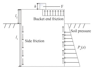 Figure 1 Diagram of horizontal force in sandy soil of bucket foundation
where δ is the friction angle of the soil and qf is the friction resistance per unit circumference of the bucket. The bending moment due to frictional resistance is represented by:
$$ M_0=8 q_f r^2 $$ (3) The primary source of upward vertical force for the bucket foundation comes from frictional resistance at the bucket wall, and K is assumed to be 0.5. The effect of the soil inside the bucket on the bottom section of the top cover must be taken into account when the foundation is in place and the top of the bucket comes into contact with the mud surface. The bearing capacity is not affected by the foundation’s inclination. The soil within the bucket roof is currently generating an overturning moment. The corresponding equations are as follows:
$$ M_p=W_p r_b $$ (4) $$ r_b=\frac{4 r}{3 {\rm{ \mathsf{ π} }}} $$ (5) where Wp is the weight of the bucket, and rb is the distance between the center of gravity of the semicircle and the center of the circle.
The moment balance equation can be written as Equation (6). The bucket will rotate under the horizontal force, the distance between the center of rotation and the top of the bucket is fixed, and then, using Equation (7), one can determine the horizontal ultimate bearing capacity of suction bucket foundation in sand.
$$ \begin{gathered} \int_0^{l_1-l_2} p_u(x) Z\left(h+l_2+x\right) \mathrm{d} x- \\ \int_{l_0-l_2}^{l_1-l_2} p_u(x) Z\left(h+l_2+x\right) \mathrm{d} x-M_0-M_p=0 \end{gathered} $$ (6) $$ F_H=\int_0^{l_1-l_2} p_u(x) Z \mathrm{~d} x-\int_{l_0-l_2}^{l_1-l_2} p_u(x) Z \mathrm{~d} x $$ (7) 2.2 Experimental model
The TF is a steel construction that consists primarily of a suction bucket foundation, a transition section, and an upper loading rod. The bucket skirt structure is constructed using aluminum plate, while the base top cover is fabricated from plexiglass. Notably, each bucket top cover is equipped with four drainage apertures. As indicated in Figure 2, the experimental investigation is categorized into three distinct configurations of TFs, characterized by varying heights: 150 mm, 250 mm, and 350 mm. The bucket exhibits a diameter of 300 mm, accompanied by a lateral separation of 300 mm between its opposing sides. Furthermore, the bucket skirt’s wall thickness is measured at 1.5 mm. The structure is made of all-steel material, with a density of 7 800 kg/m3, an elastic modulus of E=210 GPa, and a yield strength of 345 MPa. The model numbers and dimension characteristics of the TF are shown in Table 1.
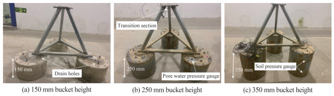 Figure 2 TF with three different bucket skirt heightsTable 1 Model number and size parameters
Model Skirt diameter (mm) Skirt wall thickness (mm) Skirt height (mm) Bucket side spacing (mm) Bucket top thickness (mm) Aspect ratio M1 300 1.5 150 300 10 0.5 M2 300 1.5 250 300 10 0.83 M3 300 1.5 350 300 10 1.17 2.3 Soil properties
Fujian standard sand was utilized in the experiment, and the particle gradation is depicted in the Figure 3. The sand under consideration possesses a coefficient of inhomogeneity of 1.94 and a coefficient of curvature of 1.43. Consequently, the sand employed in this experimental investigation can be characterized as homogeneous with discontinuous gradation. The relative density of the sandy soil is measured at 0.45.
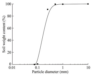 Figure 3 The particle gradation
The specific parameters of the sandy soil are shown in Table 2.
Table 2 Fujian standard sandy soil parametersSoil properties Dr k (cm/s) Φ (°) Gs c (kPa) W (%) e Standard sand 0.45 0.003 9 31.9 2.67 2.5 22.41 0.57 In the experimental assessment, a steel soil containment vessel, as depicted in Figure 4 (a), measuring dimensions of 2 m by 2 m by 1.5 m, was utilized. To facilitate observation of the interior conditions, the front of the container was equipped with high-strength tempered glass, while the remaining surfaces were constructed using steel plates. The bottom of the soil container was equipped with drainage pipes arranged in a well-like pattern, and the spaces between them were filled with permeable stones. To prevent sand from entering the drainage pipes during the drainage process, geotextiles were installed on the upper portion to obstruct any flow into the drain pipe. Following the completion of water injection, the falling sand method was employed to uniformly load the test sand into the soil container. In this experiment, the test model was subjected to monotonic displacement loading mode utilizing a displacement control approach. Figure 4 (b) provides an illustration of the loading device.
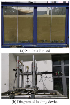 Figure 4 Experimental device and soil box
The model must be surrounded by monitoring devices such as soil pressure gauges, pore water pressure gauges, inclinometers, laser displacement gauges, tension and pressure sensors, and wire displacement gauges throughout the experiment. Specifically, the pore water pressure sensor was positioned on both the upper and lower sides of the bucket top cover to monitor changes in pore water pressure before and after the loading process. Simultaneously, the soil pressure sensor was arranged on the outer surface of the bucket skirt to monitor changes in soil pressure at the corresponding position of the bucket skirt during the loading process. The stay wire displacement gauges were placed at the upper and lower portions of the loading device to track the movement of the top of the loading rod during the loading operation and the settlement of the tripod bucket foundation. In total, three laser displacement meters were installed, which were used to measure the displacement of the loading rod and the deviation of the foundation in the direction of tension or compression of the single pile during loading. To monitor the three changes in the general inclination angle of the foundation, an inclinometer was mounted on top of the loading rod. Figure 5 illustrates the precise displacement configuration of the sensors. The 250 mm and 350 mm earth pressure gauges were placed 10 cm and 20 cm from the top bucket, respectively, outside the bucket wall. The pore water pressure gauges are arranged in three suction buckets; the two pore water pressure gauges of 1# are positioned in the upper and lower thirds of the bucket, while the remaining two are arranged at the bottom of 2# and 3#, respectively.
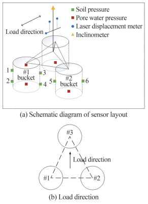 Figure 5 Schematic diagram of the test description
In order to more effectively calculate the horizontal bearing capacity of the suction barrel foundation in the saturated sand foundation under monotonic horizontal loading conditions, so that the simulation process is as close to reality as possible, the displacement control method is used to apply the horizontal load, regardless of the eccentric horizontal load, and the displacement is gradually applied, and its action point is at the top center of the axis of the overall structure of the TFs.
3 Test calculation results and analysis
In this series of tests, TFs with bucket skirt heights of 150 mm, 250 mm, and 350 mm were chosen for analysis of the horizontal bearing capacity test, and by controlling various loading angles, the impact of various bucket skirt heights on the horizontal bearing capacity of TFs was investigated. Before the experiment, the sand and soil need to be prepared and maintained. Suction sinking will be used to lower the three buckets’ foundation to the predetermined location, and the weights will be applied in accordance with the working conditions stated in Table 3. The Byrne tangent intersection method was used in this experiment to choose the horizontal ultimate bearing capacity of the suction bucket foundation (Zhu, et al., 2013). The exact steps are as follows: in the load-displacement curve that was created, draw two tangent lines at the curve’s beginning point and the position where the corner emerges; the ordinate formed by the junction of the two tangent lines represents the horizontal ultimate bearing capacity. The structure is said to have attained its maximum horizontal bearing capacity when the vertical inclination angle of the TF is more than 2°. The diameter of the suction bucket is assumed to be 3.5 times the loading height in accordance with studies in the published literature (Kim et al., 2014; Cheng, et al., 2016; Byrne and Houlsby, 2002).
Table 3 Classification of test conditionsExperiment condition number Model number Bucket skirt height (mm) Loading speed (mm/s) Loading angle (°) Drain method Loading height (cm) A1 M1 150 1 0 Undrained 105 A2 M1 150 1 180 Undrained 105 A3 M1 150 1 0 Drained 105 B1 M2 250 1 0 Undrained 105 B2 M2 250 1 180 Undrained 105 C1 M3 350 1 0 Undrained 105 C2 M3 350 1 180 Undrained 105 The correlation between different bucket heights and loading angles regarding the horizontal ultimate bearing capacity of the tripod foundation under undrained conditions is showed in Figure 6. In the case of a bucket height of 150 mm, the adjustable independent variables included the loading angle and drainage conditions (Condition A). The horizontal ultimate bearing capacity of the tripod foundation (TF) was attained in Condition A1, with a horizontal displacement approaching 10.40 mm, corresponding to an approximate force of 145.80 N, as determined from a comparative analysis of displacement-load curves. Under identical conditions, with the loading angle set at 180° (Condition A2), the foundation achieved its maximum bearing capacity at a horizontal displacement of 9.87 mm, corresponding to a force of 135.70 N. Upon increasing the bucket height to 250 mm, the load-displacement curve exhibited a similar trend to that observed with a bucket skirt height of 150 mm. A comparative examination of working conditions B1 and B2 revealed that the foundation reached the limit state of horizontal bearing capacity when horizontal loading displacements reached 13.89 mm and 16.55 mm, respectively. The corresponding horizontal forces at these instances were 252.97 N and 210.24 N, respectively. With a bucket height of 350 mm (Condition C1), the tripod foundation achieved horizontal bearing capacity limits at a horizontal displacement of 17.32 mm, yielding a force of 364.74 N. Applying reverse displacement (C2-180°) to the foundation under this bucket height resulted in horizontal failure when the horizontal displacement reached 16.31 mm, and the corresponding bearing capacity was approximately 332.08 N.
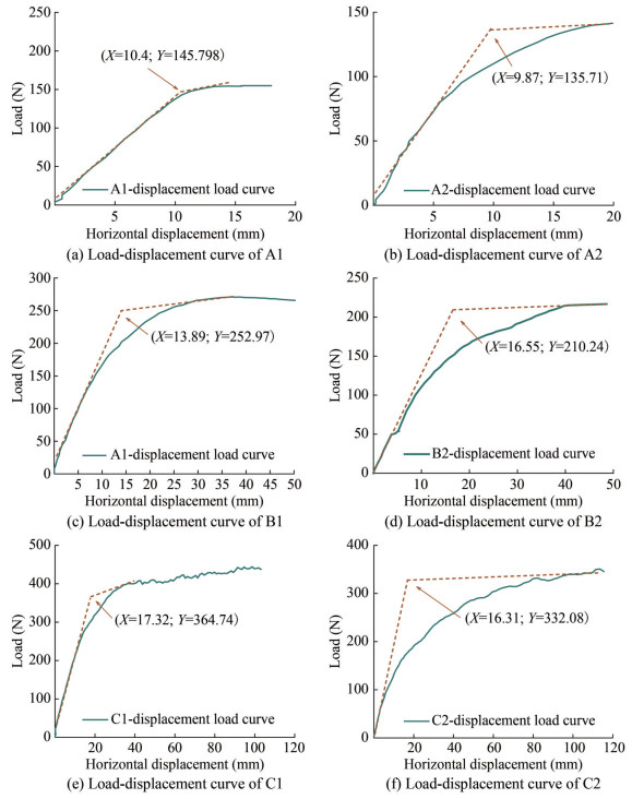 Figure 6 Displacement load curve (tangent intersection method)
Through the horizontal comparison of the three different conditions of A, B and C (as shown in Figure 7), it can be found that as the height of the bucket skirt increases, the horizontal displacement of the TF when the bearing capacity limit state occurs will increase accordingly. Particularly, when the bucket skirt height advances from 250 mm to 350 mm, the discernible regularity in displacement alteration becomes less pronounced, and the disparity between these two values becomes negligible.
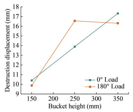 Figure 7 Effect of bucket height on horizontal displacement during failure
The load-displacement curves of TFs with skirt heights of 150 mm, 250 mm, and 350 mm are compared in Figure 8. It can be seen that the skirt height is critical to the horizontal ultimate bearing capacity of the TF. For each increment of 100 mm in skirt height and 0.33 in the length-to-diameter ratio, the horizontal ultimate bearing capacity experiences an approximate 73.5% and 44.2% enhancement, respectively, in comparison to the preceding foundation height. Furthermore, the bearing capacity of the foundation under 0° loading surpasses that under 180° loading. The range of bucket skirt heights spans from 150 mm to 350 mm, leading to a reduction in horizontal bearing capacity by approximately 6.9%, 16.9%, and 8.9% in the 180-degree direction in contrast to the 0-degree direction.
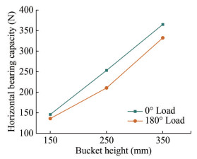 Figure 8 Effect of bucket height on horizontal bearing capacity
The drainage situation serves as the controlling factor when comparing conditions A1 and A3. The horizontal bearing capacity under the condition of 0° loading and compression of the single pile is substantially enhanced, by almost 30.4% compared to the drained condition. As can be shown in Figure 9, another critical feature influencing the horizontal bearing properties of the TF is the drainage condition. When the drainage condition is the only variable regulated, the horizontal ultimate bearing capacity of the TF under the undrained condition is significantly enhanced over the former. As a consequence, drainage will lower the bearing capacity of the TF to a certain level. Consequently, in the project, it is vital to shut the valve on top of the bucket after the TF is laid down to ensure that the foundation is in undrained condition and to maintain a specific negative pore pressure. due to that, the TF can achieve a favorable bearing effect.
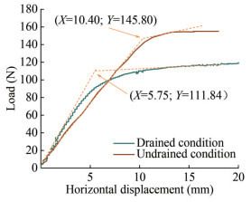 Figure 9 Effect of drainage conditions on horizontal bearing capacity
Under the A1 condition, 1# bucket is in a state of compression under the action of horizontal force, 2# and 3# are in a state of tension, and the foundation reaches the maximum horizontal bearing capacity when the horizontal displacement is 10.5 mm. In the loading stage with a horizontal displacement of 0‒10.5 mm, the soil pressure at the upper part of the front end of the 1# bucket gradually increased by about 2 kPa, and the soil pressure at the lower part of the front end of the bucket decreased by about 1.8 kPa. The earth pressure value at the back end of the 1# bucket, 10 cm from the top, has been falling, with the maximum magnitude being around 7 kPa. When the horizontal displacement is 13.89 mm under B1 conditions, the foundation achieves the limit state of horizontal bearing capacity.
In the range of 0‒13.89 mm displacement, the soil pressure at the lower section of the leading edge of the 1# bucket experiences an increase of approximately 4 kPa. Conversely, the earth pressure at the lower section of the trailing edge of the 2# bucket consistently decreases, registering an amplitude of approximately 3.8 kPa, as illustrated in Figure 9 (b). The soil pressure value at the lower section of the front end of the bucket increases and subsequently decreases, with the maximum magnitude being around 8 kPa. During the loading operation, the three soil pressure gauges on the upper half of the 1# bucket and the bottom part of the rear end did not change considerably, indicating a significantly smaller trend.
When the displacement is 17.32 mm under C1 conditions, the foundation reaches the horizontal bearing limit, the soil pressure at the upper part of the front end of 1# bucket increases by about 1 kPa, the earth pressure value at the lower part of the front end of 1# bucket increases by about 0.75 kPa, and the soil pressure at the lower part of the rear end of 1# bucket increases by about 0.75 kPa. The pressure number continues to fall, and its decreasing range is the widest, falling by around 4 kPa.
The pore water pressure change values for bucket heights of 150 mm and 350 mm are shown in Figure 10. The 1#, 2#, and 3# buckets of the TF were used in the A2 condition to get the change curve of the relative change value of the hole pressure gauges with horizontal displacement. In accordance with the observations in Figure 11 (a), when subjected to horizontal loading and pulled, the pore water pressure beneath the roof of the 1# bucket decreases with an increase in horizontal loading displacement, exhibiting a diminished amplitude of approximately 2.25 kPa. Nevertheless, the alterations in pore water pressure beneath the roofs of 2# and 3#, as well as above the top cover of 1#, are not immediately evident. The outcomes of the C2 test configuration are presented in Figure 11 (b). When the 1# bucket is subjected to tension in the horizontal direction, the pore water pressure beneath its roof decreases in tandem with the increment of horizontal displacement, registering an amplitude of approximately 3 kPa. Conversely, the pore water pressure readings beneath the tops of 2# and 3#, as well as above the top cover of 1#, exhibit no discernible variations.
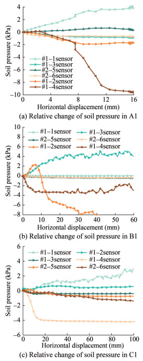 Figure 10 Relative change of soil pressure under different bucket heights
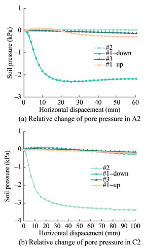 Figure 11 Relative change of pore water pressure at different bucket heights
4 Comparative analysis of finite element results
4.1 Finite element model establishment
The finite element model (FEM) is executed in accordance with the test model. It was analyzed by ABAQUS finite element, the Mohr-Coulomb elastoplastic constitutive model was adopted for the soil part, the foundation and foundation were uniformly used hexahedron, and the friction coefficient of the contact surface of the soil mass and the suction bucket was 0.35. The contact mode is free contact, that is, the two contact surfaces can be relatively separated, and the allowable relative sliding distance between the main and slave contact surfaces is 0.02. The TF skirt height is 150 mm, the diameter is 300 mm, the wall thickness is 1.5 mm, the elastic modulus density is 2 700 kg/m3, E= 70 GPa, and the yield strength is 170 MPa in the FEM; the loading rod and connecting section are made of steel with a density of 7 800 kg/m3, an elastic modulus of E=210 GPa, and yield strength of 345 MPa. The loading rod has a diameter of 30 mm and a length of 1 500 mm. The scale of the FEM soil modeling is perfectly compatible with the size of the soil in the test soil tank, which is 2 m×2 m×1 m. The grid type of the soil body and skirt structure is C3D8R, and the grid type of the transition section of the loading frame is S4R. In order to ensure the accuracy and efficiency of the FEM calculation, the grid division around the bucket is denser when the grid is divided, and the grid division at the edge of the soil is relatively sparse. The numerical model soil parameters are shown in Table 4. The soil grid division is shown in Figure 12.
Table 4 Numerical model soil parametersSoil properties Floating density, ρ (kg/m3) Modulus of elasticity, E (MPa) Poisson’s ratio Friction angle (°) Cohesi on (kPa) Standard sand 895 20 0.3 30 6 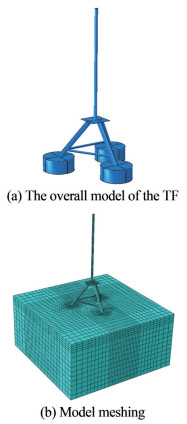 Figure 12 Finite element calculation model
4.2 Result verification
The FEM loading matches the test circumstances, with the horizontal displacement and load applied at a height of 3.5 times the diameter and the beginning displacement set to 0.15 m. The computation is terminated when the set displacement is attained or the displacement load curve has a clear inflection point. Figure 13 compares the calculation and test results of the finite element load-displacement curves of the TF under the parameters of 150 mm bucket skirt height, no drainage, and loading angles of 0° and 180°.
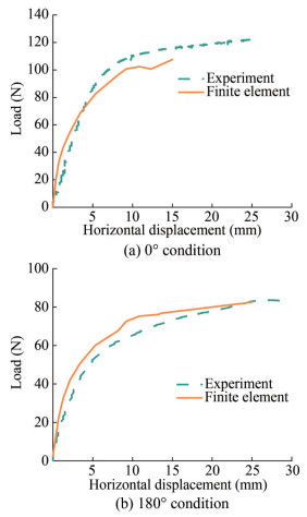 Figure 13 Comparison between FEM and experiment
In conclusion, compared with the experiment data, the fitting law of the load-displacement curve is basically the same, and the inflection point of the curve corresponds to the horizontal loading displacement is basically the same, and the load value obtained by the FEM is slightly larger than the test data at the same loading displacement.
4.3 FEM analysis of soil plastic strain and displacement
A thorough comparison of the results of the TF’s horizontal bearing capacity calculated using finite elements reveals that these methods can both accurately calculate and analyze the horizontal bearing characteristics while also accurately reflecting the interaction between the soil and the barrel during testing. As a consequence, additional study on the soil changes and displacement laws around the TF following loading may be done using the Abaqus finite element program (Liu, et al., 2017; Sun, et al., 2020; Hirai, 2020).
The distribution of the soil plastic zone when achieving the horizontal ultimate bearing capacity is illustrated in Figure 14, considering the TF with a bucket skirt height of 150 mm and a loading angle of 0°. Figure 14 (a) and (c) show that when the ultimate load is reached, the soil below the skirt height has no plastic deformation due to the skirt’s low height. According to the cloud map of local plastic distribution of the soil around the compressed bucket in Figure 14 (b), it can be seen that the plastic deformation of the soil is mainly concentrated in the upper half of the bucket, and the plastic strain of the surrounding soil occurs under the action of the single pile The value is greater than the plastic strain value of the surrounding soil under the action of two tension buckets.
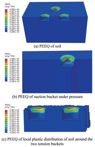 Figure 14 Distribution of soil plastic zone around TF with loading angle of 0°
The soil plastic zone distribution diagrams are presented in Figure 15, depicting a skirt height of 150 mm and a loading angle of 180° when reaching the horizontal ultimate bearing capacity. Comparable to the plastic zone distribution in the soil surrounding the Tripod Foundation (TF) under a loading angle of 0°, there is an absence of plastic deformation in the soil beneath the bucket skirt height. Moreover, the plastic strain induced in the surrounding soil by the two compression buckets exceeds that induced by the tension bucket.
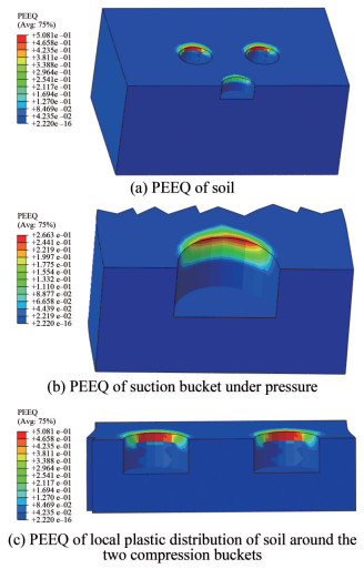 Figure 15 Distribution of soil plastic zone around TF with loading angle of 180°
The soil deformation diagrams are given in Figure 16. The TF, possessing a bucket skirt height of 150 mm, attains the ultimate bearing capacity at loading angles of 0° and 180°, respectively. The unit of deformation is the meter. Soil rotation center of the TF is located on the line connecting the front and rear buckets, near the pressure bucket. The deformation of the soil mass in the front and rear parts of the skirt of the barrel foundation is approximately vertical When combined with the law of soil pressure distribution, it is clear that under the horizontal load of the TF, the upper horizontal load loading mode leads to a tension-compression bearing mode of the foundation. Thus, under the influence of a horizontal load, the soil pressure on the lower portion of the roof rises and falls in the direction of the load and the direction of the backload, respectively, causing tension-compression failure.
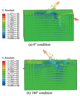 Figure 16 Soil deformation Law of TF under basic conditions
5 Conclusion
This paper investigates the horizontal bearing characteristics of the TF. When calculating the bearing capacity through horizontal displacement, various length-to-diameter ratios, loading angles, and drainage conditions are taken into account. The horizontal ultimate bearing capacity of the 150 mm, 250 mm, and 350 mm suction buckets is determined. The conclusions are as follows:
Different bucket skirt heights profoundly influence the bearing characteristics of the TF. The test results indicate that under undrained conditions, the larger the length-to-diameter ratio of the bucket skirt, the greater the bearing capacity. There is a substantial increase in the horizontal ultimate bearing capacity of the TF with increasing skirt height. When the loading angle is 0°, the bearing capacity increases by 74% and 150% with the increase in skirt height (per 100 mm). In other words, the aspect ratio increases by 0.33. When the angle is 180°, the bearing capacity increases by 55% and 144% with the increase in aspect ratio (per 0.33), respectively.
The bearing properties of the TF are significantly influenced by different loading orientations. Under drained conditions, in the loading direction of 0°, the horizontal ultimate bearing capacity of the TF with a skirt height of 350 mm and 250 mm is 155% and 68% higher than that of the skirt height of 150 mm, respectively. Simultaneously, when the loading angle is 0°, the horizontal ultimate bearing capacity of the foundation exceeds that of the foundation when the loading angle is 180°. Therefore, in practical engineering, the external load should be directed toward any single pile of the TF as much as possible to fully utilize the bearing effect of the bucket foundation.
The change in the height of the bucket skirt significantly affects the value of earth pressure near the bucket, especially the 1# bucket under the condition of a single pile under pressure. The changes in active and passive earth pressure on the front and rear sides of the bucket are conspicuous. Additionally, the pore water pressure beneath the pressure bucket cover is influenced by the skirt’s height. The pore water pressure under the cover rises with height, increasing by approximately 0.375 kPa for every 100 mm.
Experiments have shown that when the valve is closed, the basic horizontal bearing capacity of the loading increases by approximately 30.4% compared to when the valve is open. In practice, sealing the valve at the top of the foundation can ensure a certain negative pressure in the bucket, enhancing its horizontal bearing capacity.
The distribution law of the plastic zone of the soil around the bucket reveals that under the action of horizontal load, the plastic strain of the soil around the bucket is greater than that around the bucket under tension. According to the law of soil deformation, the failure mode of the TF is the tension-compression failure mode.
Competing interest The authors have no competing interests to declare that are relevant to the content of this article. -
Figure 1 Diagram of horizontal force in sandy soil of bucket foundation
Figure 2 TF with three different bucket skirt heights
Figure 3 The particle gradation
Figure 4 Experimental device and soil box
Figure 5 Schematic diagram of the test description
Figure 6 Displacement load curve (tangent intersection method)
Figure 7 Effect of bucket height on horizontal displacement during failure
Figure 8 Effect of bucket height on horizontal bearing capacity
Figure 9 Effect of drainage conditions on horizontal bearing capacity
Figure 10 Relative change of soil pressure under different bucket heights
Figure 11 Relative change of pore water pressure at different bucket heights
Figure 12 Finite element calculation model
Figure 13 Comparison between FEM and experiment
Figure 14 Distribution of soil plastic zone around TF with loading angle of 0°
Figure 15 Distribution of soil plastic zone around TF with loading angle of 180°
Figure 16 Soil deformation Law of TF under basic conditions
Table 1 Model number and size parameters
Model Skirt diameter (mm) Skirt wall thickness (mm) Skirt height (mm) Bucket side spacing (mm) Bucket top thickness (mm) Aspect ratio M1 300 1.5 150 300 10 0.5 M2 300 1.5 250 300 10 0.83 M3 300 1.5 350 300 10 1.17 Table 2 Fujian standard sandy soil parameters
Soil properties Dr k (cm/s) Φ (°) Gs c (kPa) W (%) e Standard sand 0.45 0.003 9 31.9 2.67 2.5 22.41 0.57 Table 3 Classification of test conditions
Experiment condition number Model number Bucket skirt height (mm) Loading speed (mm/s) Loading angle (°) Drain method Loading height (cm) A1 M1 150 1 0 Undrained 105 A2 M1 150 1 180 Undrained 105 A3 M1 150 1 0 Drained 105 B1 M2 250 1 0 Undrained 105 B2 M2 250 1 180 Undrained 105 C1 M3 350 1 0 Undrained 105 C2 M3 350 1 180 Undrained 105 Table 4 Numerical model soil parameters
Soil properties Floating density, ρ (kg/m3) Modulus of elasticity, E (MPa) Poisson’s ratio Friction angle (°) Cohesi on (kPa) Standard sand 895 20 0.3 30 6 -
Bang S, Cho Y (2002) Ultimate horizontal loading capacity of suction piles. International Journal of Offshore and Polar Engineering, 12(01) Bang S, Jones KD, Kim KO, Kim YS, Cho Y (2011) Inclined loading capacity of suction piles in sand. Ocean Engineering, 38(7): 915-924. https://doi.org/10.1016/j.oceaneng.2010.10.019 Byrne BW, Houlsby GT (2002) Experimental investigations of response of suction caissons to transient vertical loading. Journal of Geotechnical and Geoenvironmental Engineering, 128: 926-939 https://doi.org/10.1061/(ASCE)1090-0241(2002)128:11(926) Cheng X, Wang J, Wang Z (2016) Incremental elastoplastic fem for simulating the deformation process of suction caissons subjected to cyclic loads in soft clays. Applied Ocean Research, 59: 274-285. https://doi.org/10.1016/j.apor.2016.05.015 Ding HY, Wang L, Zhang PY (2018) Study on the lateral bearing capacity of single-helix pile for offshore wind power: Proceedings of the ASME 37th International Conference on Ocean, Offshore and Arctic Engineering, Vol 9 Hirai H (2020) Analysis of Cylindrical and Rectangular Bucket Foundations Subjected to Vertical and Lateral Loads in Sand Using a Three-Dimensional Displacement Approach. Soils and Foundations, 60(1): 45-62. https://doi.org/10.1016/j.sandf.2020.01.001 Hung LC, Kim S (2014) Evaluation of combined horizontal-moment bearing capacities of tripod bucket foundations in undrained clay. Ocean Engineering, 85: 100-109 https://doi.org/10.1016/j.oceaneng.2014.04.025 Hung LC, Kim SR (2012) Evaluation of vertical and horizontal bearing capacities of bucket foundations in clay. Ocean Engineering, 52: 75-82 https://doi.org/10.1016/j.oceaneng.2012.06.001 Kim D, Choo YW, Kim JH, Kim S Kim DS. (2014) Investigation of monotonic and cyclic behavior of tripod suction bucket foundations for offshore wind towers using centrifuge modeling. Journal of Geotechnical and Geoenvironmental Engineering, 2014, 140: 4014008. https://doi.org/10.1061/(ASCE)GT.1943-5606.0001083 Liu MM, Lian JJ, Yang M (2017) Experimental and numerical studies on lateral bearing capacity of bucket foundation in saturated sand. Ocean Engineering, 144: 14-20 https://doi.org/10.1016/j.oceaneng.2016.04.001 Liu SJ (2009) A Study on Bearing Capacity Behavior of Suction Multi-bucket Foundation for Offshore Wind Turbine. Dalian University of Technology Liu YG, Ding HY, Zhang PY (2016) Model tests on bearing capacity of composite bucket foundation in clay. Chinese Journal of Geotechnical Engineering, 38 (12): 2315-2321. https://doi.org/10.11779/CJGE201612022 Mahmood MR, Fattah MY, Khalaf A (2020) Experimental investigation on the bearing capacity of skirted foundations on submerged gypseous soil. Marine Georesources & Geotechnology, 38(10): 1151-1162. https://doi.org/10.1080/1064119X.2019.1656311 Sun LQ, Qi YM, Feng XW, Liu ZQ (2020) Tensile capacity of offshore bucket foundations in clay. Ocean Engineering, 197. https://doi.org/10.1016/j.oceaneng.2019.106893 Yun G, Bransby MF (2007) The undrained vertical bearing capacity of skirted foundations. Soils and Foundations, 47(3): 493-505 https://doi.org/10.3208/sandf.47.493 Zhang P, Shi J, Ding H, Guo YH (2016) Design of offshore wind power foundation with multi-bucket. Transactions of Tianjin University, 22(6): 502-507 https://doi.org/10.1007/s12209-016-2631-0 Zhao XL, Li YY, Wang X (2021) Experimental study on horizontal bearing characteristics of tripod-bucket foundation in sand. Journal of Hunan University(Natural Sciences)48 (9): 20-29 Zhu B, Byrne BW, Houlsby GT (2013) Long-term lateral cyclic response of suction caisson foundations in sand. Journal of Geotechnical and Geoenvironmental Engineering, 139: 73-83. https://doi.org/10.1061/(ASCE)GT.1943-5606.0000738 Zhu B, Zhang WL, Ying PP, Chen YM (2014) Deflection-based bearing capacity of suction caisson foundations of offshore wind turbines. Journal of Geotechnical & Geoenvironmental Engineering, 140(5): 04014013
