Wave Energy Damping due to Coupled Porous Structure and Submerged Porous Plate
https://doi.org/10.1007/s11804-023-00346-6
-
Abstract
The present study investigates the wave-damping characteristics due to the combination of bottom-standing porous structure, submerged porous plate, and fully-extended porous structure of finite width using the small amplitude wave theory. The hydrodynamic characteristics such as reflection, transmission, and dissipation coefficients are determined to analyse the wave energy dissipation by the composite breakwater using the matched eigenfunction expansion method and orthogonal mode-coupling relation. Darcy's law is incorporated to the flow through porous media. The composite breakwater system is investigated experimentally to validate and compare the numerical results with the physical model study. The complex porous effect parameter for the submerged plate is incorporated in the numerical analysis, which represents the reactance and resistance of the porous structure. The wave forces on the submerged plate and porous structure for the composite breakwater are investigated by considering the effects of changing parameters such as structural porosity, plate submergence, angle of incidence, width of the submerged porous structure and distance between the structures. The study illustrates that the increasing width of the fully-extended porous structure improves the performance of the breakwater system. The proposed study on the composite breakwater yields an useful information for wave energy attenuation, which can be designed and implemented in coastal and harbour areas to achieve wave tranquillity.Article Highlights● The hydrodynamic performance of composite breakwater consisting of porous structure and submerged plate is analysed analytically and validated using the experimental investigation.● The effect of structural and geometrical parameters are analysed for the compsite breakwater system.● The influence of the wave attenuation charecteristics along with wave force experience on the composite breakwater sustem is analysed. -
1 Introduction
Ports and harbours have become an integral part of a country's economic development, channeling most of its trade and offering a strategic location for naval deployment. A tranquil condition is essential for proper functioning facilities inside the port and harbour, which ensure the safe anchorage of marine vessels. Adequate coastal protection measures are inevitable for the safety of coastal communities. The porous structures are employed in coastal regions for the energy dissipation of gravity waves, thus creating a tranquil zone on the leeward side of the structure. The porous structures also reduces and eliminate the littoral drift, which is one of the main drawbacks of the traditional rubble mound breakwaters. The porous structure offers the advantage of allowing water to pass through the structure, thereby reducing the wave load impact on the structure and enhancing its durability, which is not the case for conventional breakwater. Moreover, the submerged porous structures are simple to construct and do not alter the coast's appealing aesthetic appearance. Further, the maintenance required for porous structures is less when compared to that of traditional breakwaters. A significant studies on wave interaction with porous structures is performed by Dick and Brebner (1968), Dattatri et al. (1978), Madsen (1983), Sulisz (1985), Dalrymple et al. (1991), Losada et al. (1991, 1995, 1996), Huang and Chao (1992) and Ting et al. (2004). The study illustrates that the the submerged porous structure is effective in the dissipation of wave energy and has pooved to be an efficient breakwater for the protection of coastal facilities.
Researchers have performed commendable studies on the breakwaters with different cross-sections and the submerged bottom-standing porous structures are highly capable of dissipating wave energy without causing any hindrance to the shoreward flow of water. Bennett et al. (1992) proposed a theory for interacting an incident plane wave with a slotted wave-screen breakwater. The study suggests a semi-empirical nonlinear term containing a head-loss coefficient that accounts for the impacts of energy dissipation in the flow through the screen. Zhu and Chwang (2001) performed an analytical study on the wave reflection characteristics due to composite porous breakwater lying on a solid foundation having a seaward slope. The study observed that the presence of a solid foundation does not have much effect on the reflection characteristics. The wave trapping by bottom standing and surface piecing porous structures backed by a rigid wall is examined by Koley et al. (2015). The wave reflection due to the surface-piercing porous structure is small compared to the bottom-standing porous structure. Somervell et al. (2018) derived an empirical formula for determining the friction coefficient of a double-walled permeable vertical breakwater consisting of two perforated walls spaced at a certain distance. Recently, Li et al. (2021) developed a new analytical solution for the oblique wave scattering by a perforated structure presenting the matrix element into a new form using the contour integral technique.
The studies on submerged horizontal porous plate proved to achieve wave attenuation and also helps in reducing the problem of littoral transport as they permit easy flow of water. The experimental study conducted by Neelamani and Reddy (1992) on the wave hydrodynamic characteristics of a rigidly fixed surface and submerged horizontal plate showed that the transmission coefficient is minimum and the reflection coefficient is maximum when the plate is at still water level. Neelamani and Gayathri (2006) experimentally studied the performance of a twin-plate wave barrier for different wave heights and wave periods and observed that the transmission coefficient reduces and the reflection coefficient increases as the relative width of the plate increase. Liu and Li (2011) formulated an alternative analytical solution for water motion over an offshore horizontal plate breakwater and found that the results were similar with the results obtained by other analytical approaches. Cho and Kim (2013) studied the interaction of incident waves with a submerged horizontal breakwater which showed that the wave-structure interaction enhances as plate width increases. Cho et al. (2013) conducted an experimental study on the dual porous submerged horizontal breakwater. The study found no significant variation in the performance of the proposed structure when the lower po rous plate is added at a gap greater than 10% of water depth. Das and Bora (2014) studied the reflection of oblique gravity waves by a rectangular porous structure placed on an elevated horizontal impermeable bottom supported by a solid vertical wall at one end. The results are compared with that of horizontal ocean bottom (without any elevation) to examine the effect of the elevated bottom. Recently, Mohapatra et al. (2018) presented an analytical study on the interaction of gravity waves with submerged flexible horizontal plates, suggesting wave attenuation depends on mooring stiffness and porous effect parameter.
Multiple porous structures have proved to be more effective than single porous structures. These structures can be either vertically or horizontally stratified or a series of structures placed at certain distances. Twu and Chieu (2000) developed an offshore breakwater composed of multiple layers of porous structures with different porosities with low values of reflection and transmission coefficients. Twu et al. (2002) studied the wave energy dissipation characteristics of vertically stratified porous structure under wave attack. The wave damping is noted to increase as the porosity and thickness of structures increases. Yang et al. (2017) studied the performance of multiple submerged porous bars near a vertical wall under wave attack using an analytical solution. The study observed that the spacing between the bars should be appropriately determined for better performance. The performance of stratified porous blocks backed by a sea wall due to the presence of flat, elevated, and stepped sea beds are studied by Venkateswarlu and Karmakar (2020). The reduction in wave force on the sea wall in the case of a stepped bed is noted when compared to a flat and elevated bed. Further, Venkateswarlu and Karmakar (2021) performed a numerical analysis on the wave-dissipating characteristics of multiple porous structures of finite thickness considering the leeward unbounded region and confined region, which suggested that the increase in the number of structures enhances wave damping.
Studies on floating-type breakwaters have been of broad interest over the years. These breakwaters are economical when there is a need to provide a calm sheltered region for a short duration as these are mobile structures that can be transported after their use, unlike the conventional breakwaters. Arunachalam (1982) conducted experimental studies on porous horizontal floating plate breakwater and found that the transmission characteristics are greatly influenced by the wave steepness and length of the breakwater. Wang and Sun (2010) experimentally studied the performance of a porous floating breakwater under waves. The study observed that the transmission reduces with increased lengths of the breakwater and the mooring force. Patil and Karmakar (2022) analysed the hydrodynamic characteristics of a floating tunnel with submerged rubble mound breakwater (SRMB). The hydrodynamic coefficient are observed to be efficient with the increased depth of submergence for increased porosity in the SRMB armour layer. Xie (2022) analysed long wave reflection from an array of trapezoidal breakwaters. The sloping seabed is noted to surpass the resonance frequency while strengthening the Bragg reflection.
The studies performed by researchers provided limited information regarding the wave-damping characteristics of combinations of different types of porous structures. Hence, to bridge the research gap, the present study analyses the wave dissipation characteristics of various combinations of bottom-standing porous structures, submerged horizontal porous plate, and fully extended porous structures. The matched eigenfunction expansion method and the orthogonal mode-coupling relation are incorporated to determine the wave transformation along with the wave force due to the composite breakwater system. The study provides insight into the optimum configuration for which the porous structure achieves maximum wave energy dissipation, enhancing the efficiency of the coastal structure.
2 Mathematical formulation for composite breakwater
The wave interaction with a combination of bottom-standing porous structure, submerged porous plate, and the fully-extended porous structure is analysed using the small-amplitude wave theory. The Cartesian coordinate system is considered with x-axis taken as horizontal and the y-axis considered vertically downward positive. The fluid domain is divided into nine regions (Figure 1), upstream open water region at 0 < x < ∞, 0 < y < h as region-1 (R1), the fluid domain above the bottom-standing porous structure at − a1 < x < 0, 0 < y < h1 is taken as region-2 (R2), bottom-standing submerged porous structure region at − a1 < x < 0, h1 < y < h is taken as region-3 (R3), fluid domain between the porous structure and porous plate at − a2 < x < − a1, 0 < y < h as region-4 (R4), fluid domain above the porous plate at − a3 < x < − a2, 0 < y < h1 as region-5 (R5), fluid domain below the submerged porous plate at − a3 < x < − a2, h1 < y < h as region-6 (R6), fluid domain between the plate and the fully extended porous structure at − a4 < x < − a3, 0 < y < h as region-7 (R7), fully-extended porous structure at − a5 < x < − a4, 0 < y < h as region-8 (R8) and downstream open water region at − ∞ < x < − a5, 0 < y < h as region-9 (R9).
The fluid is a considered to be incompressible, inviscid and the motion is irrotational and simple harmonic in time with frequency ω and the velocity potential Φj (x, y, z, t) in the respective regions are represented as $ \Phi_{j}(x, y, z, t)= \operatorname{Re}\left\{\phi_{j}(x, y) \mathrm{e}^{-\mathrm{i}l z-\mathrm{i} \omega t}\right\}$ along with the free surface deflection represented as ζj (x, z, t) = $ \operatorname{Re}\left\{\eta_{j}(x) \mathrm{e}^{-\mathrm{i} l z-\mathrm{i} \omega t}\right\}$ where Re is the real part and l = γ10 sin θ is the wavenumber in z direction, θ is the angle of incidence, γ10 is the progressive wave number in y direction and the subscript j denotes the respective regions. The velocity potential ϕj (x, y) satisfies the Helmholtz equation given by
$$ \frac{\partial^{2} \phi_{j}}{\partial x^{2}}+\frac{\partial^{2} \phi_{j}}{\partial y^{2}}-l^{2} \phi_{j}=0 \text { for } 0<y<h $$ (1) The bottom is considered to be impermeable without any elevation, and there is no flow of fluid through the sea bed. So the bottom boundary condition is of the form
$$ \frac{\partial \phi_{j}(x, y)}{\partial y}=0 \text { at } y=h \text { for } j=1, 4, 6, 7, 9 $$ (2) The linearized free surface boundary condition in open water region is given by
$$ \frac{\partial \phi_{j}(x, y)}{\partial y}+\frac{\omega^{2}}{g} \phi_{j}(x, y)=0 \text { at } y=0 \text { for } j=1, 4, 7, 9 $$ (3) The linearized free surface condition in the porous structure region for the bottom-standing porous structure is given by
$$ \begin{gathered} \frac{\partial \phi_{j}(x, y)}{\partial y}+\frac{\omega^{2}\left(s_{1}+\mathrm{i} f_{1}\right)}{g} \phi_{j}(x, y)=0 \text { at } \\ h 1<y<h \text { for } j=3 \end{gathered} $$ (4a) where s1 is the inertia coefficient and f1 is the friction coefficient for the bottom-standing porous structure. The linearized boundary condition for the porous plate at the interface is given by
$$ \frac{\partial \phi_{5}}{\partial y}=\frac{\partial \phi_{6}}{\partial y}=\mathrm{i} \gamma_{10} G_{p}\left(\phi_{6}-\phi_{5}\right) \text { for } y=h_{1} $$ (4b) where $ G_{p}=\frac{\rho b \omega}{\mu}$ is the porous effect parameter, ρ is the density of the structure, b is the material constant and μ is the dynamic viscosity constant. Further, the linearized boundary condition for the fully-extended porous structure is given by
$$ \frac{\partial \phi_{j}(x, y)}{\partial y}+\frac{\omega^{2}\left(s_{2}+\mathrm{i} f_{2}\right)}{g} \phi_{j}(x, y)=0 \quad \text { at } y=0 \text { for } j=8 $$ (4c) where s2 is the inertia coefficient and f2 is the friction coefficient of the fully-extended porous structure. The boundary condition at the interface y = h1 for the bottom-standing porous structure is given by
$$ \phi_{2}=\left(s_{1}+\mathrm{i} f_{1}\right) \phi_{3} \text { and } \frac{\partial \phi_{2}}{\partial y}=\varepsilon_{1} \frac{\partial \phi_{3}}{\partial y} $$ (5) The continuity of velocity and pressure at the edge x = 0, − a1 is given by
$$ \begin{gathered} \phi_{2}(x, y)=\left\{\begin{array}{l} \left.\phi_{1}(x, y)\right|_{x=0} \\ \left.\phi_{4}(x, y)\right|_{x=-a_{1}} \end{array} \text { and } \phi_{2 x}(x, y)=\right. \\ \left\{\begin{array}{l} \left.\phi_{1 x}(x, y)\right|_{x=0} \\ \left.\phi_{4 x}(x, y)\right|_{x=-a_{1}} \end{array} \text { for } 0<y<h_{1}\right. \end{gathered} $$ (6a) $$ \begin{gathered} \left(s_{1}+\text { i } f_{1}\right) \phi_{3}(x, y)=\left\{\begin{array}{l} \left.\phi_{1}(x, y)\right|_{x=0} \\ \left.\phi_{4}(x, y)\right|_{x=-a_{1}} \end{array} \text { and } \varepsilon_{1} \phi_{3 x}(x, y)=\right. \\ \left\{\begin{array}{l} \left.\phi_{1 x}(x, y)\right|_{x=0} \\ \left.\phi_{4 x}(x, y)\right|_{x=-a_{1}} \text { for } h_{1}<y<h \end{array}\right. \end{gathered} $$ (6b) Further, at the edge x =− aj, j = 2, 3 of the fluid and porous plate interfaces, the continuity of velocity and pressure is given by
$$ \begin{array}{l} \phi_{5}(x, y)=\left\{\begin{array}{l} \left.\phi_{4}(x, y)\right|_{x=-a_{2}} \text { and } \\ \left.\phi_{7}(x, y)\right|_{x=-a_{3}} \end{array}\right. \\ \;\;\;\;\;\;\phi_{5 x}(x, y)=\left\{\begin{array}{l} \left.\phi_{4 x}(x, y)\right|_{x=-a_{2}} \\ \left.\phi_{7 x}(x, y)\right|_{x=-a_{3}} \end{array} \text { for } 0<y<h_{1}\right. \end{array} $$ (7a) $$ \begin{aligned} & \phi_6(x, y)=\left\{\begin{array}{l} \left.\phi_4(x, y)\right|_{x=-a_2} \\ \left.\phi_7(x, y)\right|_{x=-a_3} \end{array}\right. \text { and } \\ &\;\; \;\;\;\;\phi_{6 x}(x, y)=\left\{\begin{array}{l} \left.\phi_{4 x}(x, y)\right|_{x=-a_2} \\ \left.\phi_{7 x}(x, y)\right|_{x=-a_3} \end{array} \text { for } h_1<y<h\right. \end{aligned} $$ (7b) In addition, at the edge x =− aj, j = 4, 5 of the fully-extended porous structure, the continuity of velocity and pressure is given by
$$ \begin{array}{l} \left(s_{2}+\mathrm{i} f_{2}\right) \phi_{8}(x, y)=\left\{\begin{array}{l} \left.\phi_{7}(x, y)\right|_{x=-a_{4}} \\ \left.\phi_{9}(x, y)\right|_{x=-a_{5}} \end{array}\right. \text { and } \\ \;\;\;\;\varepsilon_{2} \phi_{8 x}(x, y)=\left\{\begin{array}{l} \left.\phi_{7 x}(x, y)\right|_{x=-a_{4}}\\ \left.\phi_{9 x}(x, y)\right|_{x=-a_{5}} \end{array}\right. \text { for } 0<y<h \end{array} $$ (8) The wave number in the upstream/downstream freewater region γjn for j = 1, 4, 7, 9 and the bottom-standing porous structure region γ2n satisfies the dispersion relation for finite water depth is given by
$$ \omega^{2}=\left\{\begin{array}{l} g \gamma_{j 0} \tanh \gamma_{j 0} h \quad \text { for } \quad n=0 \\ -g \gamma_{j n} \tan \gamma_{j n} h \quad \text { for } \quad n=1, 2, \ldots . \end{array} \text { for } j=1, 4, 7, 9\right. $$ (9a) $$ \begin{array}{l} \omega^{2}-g \gamma_{2 n} \tanh \gamma_{2 n} h-F_{n}\left(\omega^{2} \tanh \gamma_{2 n} h-\gamma_{2 n} g\right)=0\\ \;\;\;\;\text { for } n=0, 1, 2, \ldots \text {. } \end{array} $$ (9b) where $ F_{n}=\frac{\left\{\left(s_{1}+\mathrm{i} f_{1}\right)-\varepsilon_{1}\right\} \tanh \gamma_{2 n}\left(h-h_{1}\right)}{\left\{\left(s_{1}+\mathrm{i} f_{1}\right)-\varepsilon_{1} \tanh ^{2} \gamma_{2 n}\left(h-h_{1}\right)\right\}}, \omega$ is the wave frequency and g is the acceleration due to gravity. Further, the wave number γ5n within − a2 < x < − a3, 0 < y < h satisfies the dispersion relation of the form for n = 0, 1, 2, ... given by
$$ \begin{gathered} \gamma_{5 n} \sinh \gamma_{5 n}\left(h-h_{1}\right)\left\{g \gamma_{5 n} \sinh \gamma_{5 n} h_{1}-\omega^{2} \cosh \gamma_{5 n} h_{1}\right\}- \\ \mathrm{i} k_{10} G_{p}\left\{\omega^{2} \cosh \gamma_{5 n} h-g \gamma_{5 n} \sinh \gamma_{5 n} h\right\}=0 \end{gathered} $$ (10) The wave number γ8n for the fully-extended porous structure satisfies the dispersion relation given by
$$ \omega^{2}\left(s_{2}+\mathrm{i} f_{2}\right)=g \gamma_{8 n} \tanh \gamma_{8 n} h \text { for } n=0, 1, 2, \ldots $$ (11) In the far-field region, the radiation conditions in the presence of a porous structure with the barrier are given by
$$ \phi_{j}(x, y)= \begin{cases}\left(I_{10} \mathrm{e}^{-\mathrm{i} \gamma_{10} x}+R_{10} \mathrm{e}^{\mathrm{i} \gamma_{10} x}\right) f_{10}(y) & \text { as } x \rightarrow \infty \\ \left(T_{90} \mathrm{e}^{-\mathrm{i} \gamma_{90} x}\right) f_{90}(y) & \text { as } x \rightarrow-\infty\end{cases} $$ (12) where I10, R10 and T90 are the complex amplitude of the incident, reflected and transmitted wave amplitudes respectively.
3 Method of solution for composite breakwater
The velocity potentials ϕj (x, y) in each of the regions satisfy the Helmholtz Equation (1) along with the boundary conditions (2) – (4) is of the form
$$ \begin{aligned} & \phi_{1}(x, y)=\left(I_{10} \mathrm{e}^{-\mathrm{i} k_{10} x}+R_{10} \mathrm{e}^{\mathrm{i} k_{10} x}\right) f_{10}(y)+ \\ &\;\;\;\; \sum\limits_{n=1}^{\infty} R_{1 n} \mathrm{e}^{-k_{1 n} x} f_{1 n}(y) \text { for } 0<x<\infty, 0<y<h \end{aligned} $$ (13a) $$ \begin{aligned} & \phi_{2}(x, y)=\sum\limits_{n=0}^{\infty}\left\{A_{2 n} \mathrm{e}^{-\mathrm{i} k_{2 n} x}+B_{2 n} \mathrm{e}^{\mathrm{i} k_{2 n}\left(x+a_{1}\right)}\right\} f_{2 n}(y) \\ &\;\; \text { for }-a_{1}<x<0, 0<y<h_{1} \\ \end{aligned} $$ (13b) $$ \begin{aligned} & \phi_{3}(x, y)=\sum\limits_{n=0}^{\infty}\left\{A_{2 n} \mathrm{e}^{-\mathrm{i} k_{2 n} x}+B_{2 n} \mathrm{e}^{\mathrm{i} k_{2 n}\left(x+a_{1}\right)}\right\} \\ &\;\; f_{3 n}(y) \text { for }-a_{1}<x<0, h_{1}<y<h \\ \end{aligned} $$ (13c) $$ \begin{aligned} & \phi_{4}(x, y)=\left(A_{40} \mathrm{e}^{-\mathrm{i} k_{40}\left(x+a_{1}\right)}+B_{40} \mathrm{e}^{\mathrm{i} k_{40}\left(x+a_{2}\right)}\right) f_{40}(y)+ \\ & \sum\limits_{n=1}^{\infty}\left\{A_{4 n} \mathrm{e}^{k_{4 n}\left(x+a_{1}\right)}+B_{4 n} \mathrm{e}^{-k_{4 n}\left(x+a_{2}\right)}\right\} f_{4 n}(y) \\ & \text { for }-a_{2}<x<-a_{1}, 0<y<h \end{aligned} $$ (13d) $$ \begin{aligned} & \phi_{5}(x, y)=\sum\limits_{n=0}^{\infty}\left\{A_{5 n} \frac{\cos k_{5 n} x}{\cos k_{5 n} a_{2}}+B_{5 n} \frac{\sin k_{5 n} x}{\sin k_{5 n} a_{3}}\right\} f_{5 n}(y) \text { for } \\ & -a_{3}<x<-a_{2}, 0<y<h_{1} \end{aligned} $$ (13e) $$ \begin{aligned} & \phi_{6}(x, y)=\sum\limits_{n=0}^{\infty}\left\{A_{5 n} \frac{\cos k_{5 n} x}{\cos k_{5 n} a_{2}}+B_{5 n} \frac{\sin k_{5 n} x}{\sin k_{5 n} a_{3}}\right\} f_{6 n}(y) \text { for } \\ & \;\;\;\;-a_{3}<x<-a_{2}, h_{1}<y<h \end{aligned} $$ (13f) $$ \begin{aligned} & \phi_{7}(x, y)=\left(A_{70} \mathrm{e}^{-i k_{70}\left(x+a_{3}\right)}+B_{70} \mathrm{e}^{\mathrm{i} k_{70}\left(x+a_{4}\right)}\right) f_{70}(y)+ \\ & \sum\limits_{n=1}^{\infty}\left\{A_{7 n} \mathrm{e}^{k_{7 n}\left(x+a_{3}\right)}+B_{7 n} \mathrm{e}^{-k_{7 n}\left(x+a_{4}\right)}\right\} f_{7 n}(y) \\ & \text { for }-a_{4}<x<-a_{3}, 0<y<h \end{aligned} $$ $$ (13g) $$ \begin{aligned} & \phi_{8}(x, y)=\sum\limits_{n=0}^{\infty}\left\{A_{8 n} \mathrm{e}^{-\mathrm{i} k_{8 n}\left(x+a_{4}\right)}+\right. \\ &\;\; \left.B_{8 n} \mathrm{e}^{\mathrm{i} k_{8 n}\left(x+a_{5}\right)}\right\} f_{8 n}(y) \text { for }-a_{5}<x<-a_{4}, 0<y<h \end{aligned} $$ (13h) $$ \begin{aligned} & \phi_{9}(x, y)=T_{90} \mathrm{e}^{-\mathrm{i} k_{90}\left(x+a_{5}\right)} f_{90}(y)+ \\ & \;\;\sum\limits_{n=1}^{\infty} T_{9 n} \mathrm{e}^{k_{9 n}\left(x+a_{5}\right)} f_{9 n}(y) \text { for }-\infty<x<-a_{5}, 0<y<h \end{aligned} $$ (13i) where I10 is the incident wave amplitude taken as unity and R1n, A2n, B2n, A4n, B4n, A5n, B5n, A7n, B7n, A8n, B8n and T9n for n = 0, 1, 2, ... the unknown constants are to be determined. The eigenfunctions for the open-water regions for j = 1, 4, 7, 9 are given by
$$ \begin{gathered} f_{j n}(y)=\frac{\cosh \gamma_{j n}(h-y)}{\cosh \gamma_{j n} h} \text { for } n=0 \text { and } \\ f_{j n}(y)=\frac{\cos \gamma_{j n}(h-y)}{\cos \gamma_{j n} h} \text { for } n=1, 2, 3, \ldots \end{gathered} $$ (14) where γjn for j = 1, 4, 7, 9 are the eigenvalues and will satisfy the open water dispersion relation as in Eq. 9(a) satisfying $ \gamma_{j n}{ }^{2}=k_{j n}{ }^{2}+l^{2}$, where $ \gamma_{j n}$ is the wave number in y direction, kjn is the wave number in x direction, and l = γ10 sin θ is the wave number in the z direction. The eigenfunctions fjn (y) for j = 2, 3 for the bottom-standing submerged porous structure region are given by
$$ f_{2 n}(y)=\left\{\frac{\cosh \gamma_{2 n}(h-y)-F_{n} \sinh \gamma_{2 n}(h-y)}{\cosh \gamma_{2 n} h-F_{n} \sinh \gamma_{2 n} h}\right\} $$ (15) $$ \begin{aligned} & f_{3 n}(y)= \\ & \quad\left\{\frac{1-F_{n} \tanh \gamma_{2 n}\left(h-h_{1}\right)}{\left(s_{1}+\mathrm{i} f_{1}\right)\left(\cosh \gamma_{2 n} h-F_{n} \sinh \gamma_{2 n} h\right)}\right\} \cosh \gamma_{2 n}(h-y) \end{aligned} $$ (16) $$ {\rm{where}}\;\; F_{n}=\frac{\left\{\left(s_{1}+\mathrm{i} f_{1}\right)-\varepsilon_{1}\right\} \tanh \gamma_{2 n}\left(h-h_{1}\right)}{\left\{\left(s_{1}+\mathrm{i} f_{1}\right)-\varepsilon_{1} \tanh ^{2} \gamma_{2 n}\left(h-h_{1}\right)\right\}} $$ (17) ε1 is the porosity, s1 is an inertial parameter, and f1 is the friction coefficient of the bottom-standing porous structure, where γ2n satisfies the dispersion relation as in Eq. (9b). The eigenfunctions for the submerged porous plate region j = 5 and 6 is given by
$$ f_{5 n}(y)=\sinh \gamma_{5 n}\left(h-h_{1}\right)\left\{g \gamma_{5 n} \cosh \gamma_{5 n} y-\omega^{2} \sinh \gamma_{5 n} y\right\} $$ (18a) $$ f_{6 n}(y)=-\left\{g \gamma_{5 n} \sinh \gamma_{5 n} h_{1}-\omega^{2} \cosh \gamma_{5 n} h_{1}\right\} \cosh \gamma_{5 n}(h-y) $$ (18b) where γ5n is the eigenvalue satisfies the dispersion relation as in Eq. (10). Further, the eigenfunctions fjn (y) for the fully-extended porous structure region at j = 8 is given by
$$ f_{8 n}(y)=\frac{\cosh \gamma_{8 n}(h-y)}{\cosh \gamma_{8 n} h} \text { for } n=0, 1, 2, \ldots $$ (19) where γ8n, n = 0, 1, 2, ... are eigenvalues and satisfies the dispersion relation as in Eq. (11). The eigenfunction fjn (y) in the open water region j = 1, 4, 7, 9 satisfy the orthogonality relation given by
$$ \left\langle f_{j m}, f_{j n}\right\rangle_{j=1, 4, 7, 9}=\left\{\begin{array}{l} 0 \text { for } m \neq n \\ C_{n} \text { for } m=n \end{array}\right. $$ (20) with respect to the orthogonal mode-coupling relation defined by
$$ \left\langle f_{j m}, f_{j n}\right\rangle_{j=1, 4, 7, 9}=\int_{0}^{h} f_{j m}(y) f_{j n}(y) \mathrm{d} y $$ (21) where $ C_{n}=\left\{\frac{2 \gamma_{j n} h+\sinh 2 \gamma_{j n} h}{4 \gamma_{j n} \cosh ^{2} \gamma_{j n} h}\right\}$ for n = 0 with Cn for n = 1, 2, 3, ... are obtained by substituting γjn = iγjn.
In order to determine the unknown coefficients, the orthogonal mode coupling relation as in Eq. (21) is employed on ϕj (x, y) and ϕjx (x, y) with the eigenfunction fjm (y) along with continuity of velocity and pressure as in Eq. (6a) across the vertical interface x = 0, 0 < y < h to obtain
$$ \begin{aligned} & \left\langle\phi_{j}(x, y), f_{j m}(y)\right\rangle_{j=1}=\int\limits_{0}^{h} \phi_{j}(x, y) f_{j m}(y) \mathrm{d} y \\ & =\int\limits_{0}^{h_{1}} \phi_{j+1}(x, y) f_{j m}(y) \mathrm{d} y+ \\ & \left(s_{1}+\mathrm{i} f_{1}\right) \int\limits_{h_{1}}^{h} \phi_{j+2}(x, y) f_{j m}(y) \mathrm{d} y \text { for } m=0, 1, 2, \ldots \\ \end{aligned} $$ (22a) $$ \begin{aligned} & \left\langle\phi_{j x}(x, y), f_{j m}(y)\right\rangle_{j=1}=\int\limits_{0}^{h} \phi_{j x}(x, y) f_{j m}(y) \mathrm{d} y \\ & =\int\limits_{0}^{h_{1}} \phi_{(j+1) x}(x, y) f_{j m}(y) \mathrm{d} y+ \\ & \varepsilon_{1} \int\limits_{h_{1}}^{h} \phi_{(j+2) x}(x, y) f_{j m}(y) \mathrm{d} y \text { for } m=0, 1, 2, \ldots \end{aligned} $$ (22b) Further, the orthogonal mode coupling relation as in Eq. (21) is employed on ϕj (x, y) and ϕjx (x, y)with the eigenfunction fjm (y) along with continuity of velocity and pressure as in Eq. (6b) across the vertical interface x = − a1, 0 < y < h to obtain
$$ \begin{aligned} & \left\langle\phi_{j}(x, y), f_{j m}(y)\right\rangle_{j=4}=\int\limits_{0}^{h} \phi_{j}(x, y) f_{j m}(y) \mathrm{d} y \\ & =\int\limits_{0}^{h_{1}} \phi_{j-2}(x, y) f_{j m}(y) \mathrm{d} y+ \\ & \left(s_{1}+\mathrm{i} f_{1}\right) \int\limits_{h_{1}}^{h} \phi_{j-1}(x, y) f_{j m}(y) \mathrm{d} y \text { for } m=0, 1, 2, \ldots \\ \end{aligned} $$ (23a) $$ \begin{aligned} & \left\langle\phi_{j x}(x, y), f_{j m}(y)\right\rangle_{j=4}=\int\limits_{0}^{h} \phi_{j x}(x, y) f_{j m}(y) \mathrm{d} y \\ & =\int\limits_{0}^{h_{1}} \phi_{(j-2) x}(x, y) f_{j m}(y) \mathrm{d} y+ \\ & \varepsilon_{1} \int\limits_{h_{1}}^{h} \phi_{(j-1) x}(x, y) f_{j m}(y) \mathrm{d} y \text { for } m=0, 1, 2, \ldots \end{aligned} $$ (23b) Now, due to the presence of the submerged floating plate, the orthogonal mode coupling relation as in Eq. (21) is employed on ϕj (x, y) and ϕjx (x, y) with the eigenfunction fjm (y) along with continuity of velocity and pressure as in Eq. (7a) across the vertical interface x = – a2, 0 < y < h to obtain
$$ \begin{aligned} & \left\langle\phi_{j}(x, y), f_{j m}(y)\right\rangle_{j=4}=\int\limits_{0}^{h} \phi_{j}(x, y) f_{j m}(y) \mathrm{d} y \\ & =\int\limits_{0}^{h_{1}} \phi_{j+1}(x, y) f_{j m}(y) \mathrm{d} y+ \\ & \int\limits_{h_{1}}^{h} \phi_{j+2}(x, y) f_{j m}(y) \mathrm{d} y \text { for } m=0, 1, 2, \ldots \\ \end{aligned} $$ (24) $$ \begin{aligned} & \left\langle\phi_{j x}(x, y), f_{j m}(y)\right\rangle_{j=4}=\int\limits_{0}^{h} \phi_{j x}(x, y) f_{j m}(y) \mathrm{d} y \\ & =\int\limits_{0}^{h_{1}} \phi_{(j+1) x}(x, y) f_{j m}(y) \mathrm{d} y+ \\ & \int\limits_{h_{1}}^{h} \phi_{(j+2) x}(x, y) f_{j m}(y) \mathrm{d} y \text { for } m=0, 1, 2, \ldots \end{aligned} $$ (24b) Further, the orthogonal mode coupling relation as in Eq. (21) is employed on ϕj (x, y) and ϕjx (x, y) with the eigenfunction fjm (y) along with continuity of velocity and pressure as in Eq. (7b) across the vertical interface x =− a3, 0 < y < h to obtain
$$ \begin{aligned} & \left\langle\phi_{j}(x, y), f_{j m}(y)\right\rangle_{j=7}=\int\limits_{0}^{h} \phi_{j}(x, y) f_{j m}(y) \mathrm{d} y \\ & =\int\limits_{0}^{h_{1}} \phi_{j-2}(x, y) f_{j m}(y) \mathrm{d} y+ \\ & \int\limits_{h_{1}}^{h} \phi_{j-1}(x, y) f_{j m}(y) \mathrm{d} y \text { for } m=0, 1, 2, \ldots \\ \end{aligned} $$ (25a) $$ \begin{aligned} & \left\langle\phi_{j x}(x, y), f_{j m}(y)\right\rangle_{j=7}=\int\limits_{0}^{h} \phi_{j x}(x, y) f_{j m}(y) \mathrm{d} y \\ & =\int\limits_{0}^{h_{1}} \phi_{(j-2) x}(x, y) f_{j m}(y) \mathrm{d} y+ \\ & \int\limits_{h_{1}}^{h} \phi_{(j-1) x}(x, y) f_{j m}(y) \mathrm{d} y \text { for } m=0, 1, 2, \ldots \end{aligned} $$ (25b) Again, due to the presence of a fully-extended porous structure, the orthogonal mode coupling relation as in Eq. (21) is employed on ϕj (x, y) and ϕjx (x, y) with the eigenfunction fjm (y) along with continuity of velocity and pressure as in Eq. (8) across the vertical interface x =− a4, 0 < y < h to obtain
$$ \begin{aligned} & \left\langle\phi_{j}(x, y), f_{j m}(y)\right\rangle_{j=7}=\int\limits_{0}^{h} \phi_{j}(x, y) f_{j m}(y) \mathrm{d} y \\ & =\left(s_{2}+\mathrm{i} f_{2}\right) \int\limits_{0}^{h} \phi_{j+1}(x, y) f_{j m}(y) \mathrm{d} y \text { for } m=0, 1, 2, \ldots \\ \end{aligned} $$ (26a) $$ \begin{aligned} & \quad\left\langle\phi_{j x}(x, y), f_{j m}(y)\right\rangle_{j=7}=\int\limits_{0}^{h} \phi_{j x}(x, y) f_{j m}(y) \mathrm{d} y \\ & =\varepsilon_{2} \int\limits_{0}^{h} \phi_{(j+1) x}(x, y) f_{j m}(y) \mathrm{d} y \text { for } m=0, 1, 2, \ldots \end{aligned} $$ (26b) Further, the orthogonal mode coupling relation as in Eq. (21) is employed on ϕj (x, y) and ϕjx (x, y) with the eigenfunction fjm (y) along with continuity of velocity and pressure as in Eq. (8) across the vertical interface x =− a5, 0 < y < h to obtain
$$ \begin{array}{l} \left\langle\phi_{j}(x, y), f_{j m}(y)\right\rangle_{j=9}=\int\limits_{0}^{h} \phi_{j}(x, y) f_{j m}(y) \mathrm{d} y \\ \;\;=\left(s_{2}+\mathrm{i} f_{2}\right) \int\limits_{0}^{h} \phi_{j-1}(x, y) f_{j m}(y) \mathrm{d} y \text { for } m=0, 1, 2, \ldots \\ \end{array} $$ (27a) $$ \begin{gathered} \left\langle\phi_{j x}(x, y), f_{j m}(y)\right\rangle_{j=9}=\int\limits_{0}^{h} \phi_{j x}(x, y) f_{j m}(y) \mathrm{d} y \\ =\varepsilon_{2} \int\limits_{0}^{h} \phi_{(j-1) x}(x, y) f_{j m}(y) \mathrm{d} y \text { for } m=0, 1, 2, \ldots \end{gathered} $$ (27b) The infinite sums presented in Eqs. (22)–(27) is truncated up to finite M terms to obtain a linear system of 12 (M + 1) algebraic equations for the determination of 12 (M + 1) unknowns, and the wave reflection and transmission due to the combined bottom-standing porous structure, submerged plate and fully-extended porous structure are obtained as
$$ K_{r}=\left|\frac{R_{10}}{I_{10}}\right| \text { and } K_{t}=\left|\frac{T_{90}}{I_{10}}\right| $$ (28a) Due to the existence of porous blocks, the energy dissipation in the wave propagation through the porous structure is represented as
$$ K_{d}=1-K_{r}^{2}-K_{t}^{2} $$ (28b) The wave force acting on the front and back side of the bottom-standing porous structure can be represented as
$$ K_{\mathrm{fs}_{1}}^{1}=\frac{F_{f}^{1}}{2 \rho g I_{10} h} \quad \text { and } \quad K_{\mathrm{fs}_{2}}^{1}=\frac{F_{b}^{1}}{2 \rho g I_{10} h} $$ (29a) $$ {\rm{where}} \; F_{f}^{1}=\mathrm{i} \rho \omega \int\nolimits_{h_{1}}^{h}\left(\phi_{3}-\phi_{1}\right) \mathrm{d} y \; {\rm{at}} \;x=0 $$ (29b) $$ F_{b}^{1}=\mathrm{i} \rho \omega \int\nolimits_{h_{1}}^{h}\left(\phi_{3}-\phi_{4}\right) \mathrm{d} y \text { at } x=-a_{1} $$ (29c) The wave force acting on the horizontal porous plate is
$$ K_{p}=\frac{F_{p}}{2 \rho g I_{10} h} $$ (30a) where
$$ F_{p}=\mathrm{i} \rho \omega \int\nolimits_{-a_{3}}^{-a_{2}}\left(\phi_{5}-\phi_{6}\right) \mathrm{d} x $$ (30b) The wave force acting on the front and back side of fully-extended porous structure can be represented as
$$ K_{\mathrm{fs}_{1}}^{2}=\frac{F_{f}^{2}}{2 \rho g I_{10} h} \text { and } K_{\mathrm{fs}_{2}}^{2}=\frac{F_{b}^{2}}{2 \rho g I_{10} h} $$ (31a) $$ {\rm{where}} \;F_{f}^{2}=\mathrm{i} \rho \omega \int\nolimits_{0}^{h}\left(\phi_{8}-\phi_{7}\right) \mathrm{d} y\; {\rm{at}} \;x=-a_{4} $$ (31b) $$ F_{b}^{2}=\mathrm{i} \rho \omega \int\nolimits_{0}^{h}\left(\phi_{8}-\phi_{9}\right) \mathrm{d} y \text { at } x=-a_{5} $$ (31c) 4 Physical modelling of composite breakwater
The experimental investigation on the wave interaction with the composite breakwater is carried out in a two-dimensional monochromatic wave flume in the Marine Structures Laboratory of the Department of Water Resources and Ocean Engineering at the National Institute of Technology Karnataka, India. The total length of the flume is 50 m, with the width and depth being 0.71 m and height of 1.1 m, respectively.
The flume has a channel length of 42 m with a bottom hinged flap-type wave generator at one end and a rubble mound spending beach of slope 1V: 10H. The bottom hinged flap-type wave generator is operated by an induction motor (11 kW, 1 450 r/m). The motor is regulated using an inverter drive with a frequency ranging 0 – 50 Hz and rotates at a varying speed of 0 – 155 r/m. The wave filters made of asbestos cement sheet are provided to eliminate the disturbance due to consecutive reflections and to polarize the waves the wave maker generates. The schematic representation of the experimental setup is presented in Figure 2 and the flume details is discussed in Table 1.
Table 1 Flume detailsTotal length (m) 50 Channel length (m) 42 Width (m) 0.74 Channel depth (m) 1.1 Maximum water depth (m) 0.5 Wave flume type Two dimensional Wave Generator Bottom hinged flap type Waves generated Monochromatic type Wave absorber Rubble mound spending beach Range of wave height generation (m) 0.06 – 0.24 Range of wave period generation (s) 1.0 – 3.0 4.1 Model scale
The fundamental of all physical modelling is similitude of the model and prototype. The surface tension and the viscous effects are negligible in the prototype, as in the real sea condition the flow will be turbulent. Also, in wave motion the gravity effect is predominant in the prototype. In such conditions Froude similitude is selected. The choice of scale, for the model test is often limited by constraints posed in the available experimental facility. In the present study, similitude is achieved by the method of dimensional analysis. To simulate the field conditions of wave height, period and depth of water by application of Froude's law, a geometrically similar model scale of 1:30 is selected for the present experimental work.
The breakwater model is tested with the existing facilities in Wave Flume laboratory of Department of Water Resources and Ocean Engineering, NITK, Surathkal. The wave height and wave period of Mangalore coast varies from 1–5.4 m, 8–12 s respectively. In the laboratory regular wave height ranges from 0.06–0.24 m and wave period ranging from 1–3 s can be generated in a maximum water depth of 0.70 m. So, for the studies, a geometrically similar scale (Table 2) of 1:30 is selected for the present experimental investigation.
Table 2 Selection of the model scaleScale Hi (m) T (s) 1 5.4 8 12 1∶10 0.1 0.54 2.53 3.8 1∶20 0.05 0.27 1.79 2.68 1∶30 0.033 0.18 1.46 2.19 1∶40 0.025 0.135 1.26 1.9 4.2 Composite porous structure with submerged plate
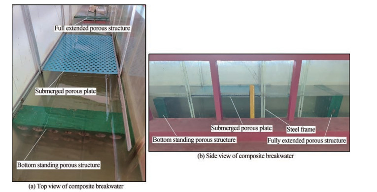
The composite structure is modelled with a 1: 30 scale using Froude's similitude criteria. The investigations are conducted for different porosity of the structure and the submerged plate on varying the wave heights H and wave periods T. The composite breakwater consists of the fully-extended porous structure, submerged plate and bottom-standing porous structure, whose dimensions are listed in Table 3.
Table 3 Structural dimensions of the model (m)Structural parameters Model dimensions Width Thickness Height/Length Bottom-standing stucture 0.72 0.15 0.25 Submerged plate 0.72 0.002 1.0 Fully extended structure 0.72 0.15 0.5 4.3 Experimental procedure
The experimental study is conducted for the composite bottom-standing porous structure, submerged porous plate, and fully-extended porous structure. The wave flume is calibrated for different water depths to obtain the incident wave heights for different combinations of wave height and wave period. The capacitance type wave probes are installed to measure the water surface elevation and the wave probes are calibrated every time before starting the experiment. The wave height is measured using three probe method as suggested by Isaacson (1991) to calculate the wave reflection. Three probes are installed before the model (in the seaward side) to measure the incident and reflected wave height. The spacing between the probes in the seaward side is adjusted to one-third of the wavelength to ensure accuracy of wave reflections (Goda and Syzuki, 1976; Isaacson, 1991). The transmitted wave heights are recorded from a probe which is placed at a distance L from the model towards the lee side. The list of experimental variables used in the present investigation is presented in Table 4 and the experimental set up for the composite breakwater is shown in Figure 3. The accuracy of the experiments is ensured by repeating the cases thrice under the same conditions.
Table 4 Experimental variables of composite breakwaterVariables Expression Parameter range Wave period (s) T 1.4, 1.6, 1.8, 2.0 Incident wave height (m) Hi 0.06, 0.08, 0.10, 0.12, 0.14 Water depth (m) h 0.45 Angle of wave attack θ 0° Incident wave steepness Hi /gT 2 0.001 5 – 0.006 2 4.4 Reflection transmission and dissipation coefficient
The wave reflection coefficient is obtained as the ratio of the reflected wave height and incident wave height reptransmission coefficient is obtained as the ratio of the transmitted wave height and incident wave height given by
$$ K_{t}=\frac{H_{t}}{H_{i}} $$ (33) The dissipation coefficient is obtained by considering the energy balance condition as in Eq. (28b). In the present study, the experimental investigation is performed to validate the numerical results obtained using the eigenfunction expansion method.
5 Numerical results and discussions
The numerical investigation for the wave interaction with the combined bottom-standing porous structure, submerged porous plate and fully extended porous structure is conducted using the small amplitude wave theory. The analysis is performed to understand the effect of structural and geometrical parameters such as structural porosity, submergence depth of plate, angle of incidence and width of the porous structures on wave energy dissipation. The reflection coefficient Kr, transmission coefficient Kt and dissipation coefficient Kd are analysed. In addition, the wave force on the front $ K_{\mathrm{fs}_{1}}^{1}$ and back $ K_{\mathrm{fs}_{1}}^{2}$ of the bottom standing porous structure, wave force on the plate Kfp, wave force on the front Kfs12 and back Kfs22 of the fully extended porous structure are also analysed. The parameters such as density of the fluid ρ = 1 025 kg/m3 and acceleration due to gravity g = 9.8 m/s2 are kept constant throughout the numerical modelling. The convergence study for the Kr and Kt due to the increasing number of evanescent modes M is performed and it is noted that, with the increasing number of evanescent mode M ≥ 10 the convergence in the reflection and transmission coefficient is evident. In order to validate the numerical model developed using the eigenfunction expansion method, the comparative study with the results of the single submerged plate (Liu and Li, 2011; Cho and Kim, 2013) and submerged porous structure (Sollitt and Cross, 1972; Sulisz, 1985) is performed and discussed in detail. Further, the experimental investigation for the combined porous structure with submerged porous plate is perfomed and the results for the experimental study are compared with the numerical results as obtained using the eigenfunction expansion method.
5.1 Validation of numerical and experimental model
The comparative study of the numerical model is performed with the results of the submerged plate (Liu and Li, 2011; Cho and Kim, 2013) and submerged porous structure (Sollitt and Cross, 1972; Sulisz, 1985) in Figure 4. The comparative study for the submerged plate (Figure 4(a)) with Liu and Li (2011) and Cho and Kim (2013) shows that the numerical result obtained using the present approach coincide with the result available in the literature. The maximum value of the reflection coefficient is observed within 1.2 < γ10h < 1.6 and with the increase in the wavenumber the Kr decreases and approaches to minimum.
The wave transformation due to the rectangular porous structure with finite thickness is compared with Sollitt and Cross (1972) and Sulisz (1985) in Figure 4 (b) on comparing the Kr and Kt for εs = 0.4 and f = 0.5. The comparative study shows a good agreement of the numerical result with Sollitt and Cross (1972). The study shows that, the wave reflection coefficient increases within 0.01 < γ10h < 1.5 and thereafter decreases. On the other hand, the transmission coefficient decreases with the increase in γ10h.
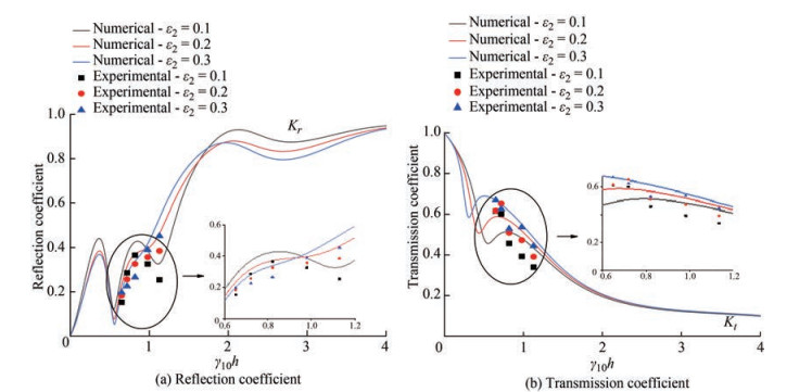
In Figure 5, the numerical investigation on the wave reflection and transmission coefficient performed for the composite porous structure with submerged plate is validated with the physical model study. The reflection coefficient Kr (Figure 5(a)) and transmission coefficient Kt (Figure 5(b)) are plotted against the non-dimensional wave number γ10h for varying plate porosity ε2. It is observed that the data obtained using the experimental study follows the similar pattern with the numerical results within the range 0.6 < γ10h < 1.2. The variation of about 5%–10% in the hydrodynamic coefficients is noted on comparing the experimental and numerical result within 0.6 < γ10h < 1.2 for different plate porosity. The variation in the numerical and experimental result may be due to consideration of the fluid to be inviscid in the numercal investigation. Further, the friction and inertia present in the model setup are unknown during the experimental investigation, but they are incorporated with assumed values during the numerical analysis which may be one of the cause in the variation in the experimental and numerical studies. Additionally, the numerical model is considered to be infinite, whereas the experimental wave tank is horizontally finite, which may potentially cause differences in the hydrodynamic coefficient values between the investigations.
5.2 Wave reflection, transmission and dissipation coefficient
The composite breakwater system's hydrodynamic performance is analyzed on studying the wave reflection, transmission and dissipation coefficients for different physical and geometrical parameters. The study performed on the wave scattering by the submerged structure enables us to understand the effectiveness of the composite breakwater system due to the action of high waves.
5.2.1 Effect of porosity of the fully-extended porous structure
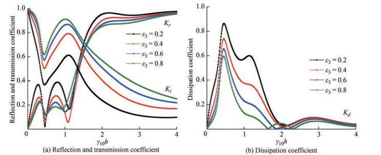
Figure 6 shows the reflection Kr, transmission Kt and dissipation Kd coefficients against the non-dimensional wave number γ10h for different porosity of fully-extended porous structure ε3 within 0.2 < ε3 < 0.8. In Figure 6(a), the reflection coefficient shows an oscillating pattern within 0.01 < γ10h < 1.15 and suddenly increases for all values of ε3. The study noted that the value of Kr is higher for minimum porosity and is lower for maximum porosity. Further, the transmission coefficient decreases upto γ10h = 0.5 and then increases within 0.5 < γ10h < 1.0 and thereafter Kt decreases with increase in γ10h. The transmission coefficient of a fully-extended porous structure also increases as the porosity increases which may be due to the fact that, as the structure's porosity increases, more water can pass through the pore space, thus increasing the transmission coefficient and decreasing the reflection coefficient. The wave energy dissipation is noted higher when the porosity of the fully-extended structure is low (Figure 6(b)). This could be due to the damping of waves within the spaces between the porous structures, as the porosity decreases. The damping coefficient is noted minimum within 1.8 < γ10h < 4.0.
5.2.2 Effect of submergence depth of plate
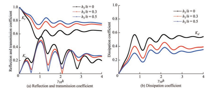
The reflection Kr, transmission Kt and dissipation Kd coefficients (Figure 7) are plotted against the non-dimensional wave number γ10h for varying plate submergence depth h1 /h. In Figure 7(a), it is observed that the reflection coefficient shows an oscillating trend as γ10h increases for all values of plate submergence depth. It is noted that the reflection coefficient decreases as the plate submergence depth increases. The reflection coefficient Kr almost remains constant for γ10h > 4 as plate submergence depth increases. Further, the transmission coefficient decreases up to γ10h = 1 and then oscillates to a constant value as in the case of the reflection coefficient. The higher submergence depths result in a higher transmission coefficient. The higher transmission coefficient with the increase in submergence depth may be due to the free flow water above the porous plate, allowing more wave transmission and less reflection. The effectiveness of the porous structure is enhanced when the porous plate is kept at the water surface level, since the wave energy dissipation (Figure 7(b)) of the structure is higher when h1 /h = 0. The wave damping is noted to decrease with the increase in the submergence depth of the plate as most of the wave energy is concentrated at the free surface.
5.2.3 Effect of angle of incidence
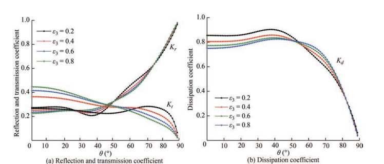
In Figure 8, the refection Kr, transmission Kt and dissipation Kd coefficients are plotted against the angle of incidence θ for various values of porosity ε3 of fully-extended porous structure. It is noted that for ε3 = 0.2, the reflection coefficient decreases slightly up to θ = 38° and then increases for higher values of angle of incidence. Whereas for higher values of porosity of fully-extended porous structure, the value of Kr increases as the angle of incidence increases. The transmission coefficent (Figure 8(a)) is observed maximum for θ = 0° and for maximum porosity of the fully-extended structure. The minimum wave reflection is observed in the range of 30° < θ < 40° which can be considered as the critical angle. Thus, it can be concluded that the critical wave angle lies within 30° < θ < 40°, which will help in the design of coastal defence structures for minimum wave reflection. The transmission coefficient decreases as the angle of incidence increases for higher values of porosity. Whereas in case of ε3 = 0.2, a slight increase in transmision coefficient is observed within 45° < θ < 75° after which the value of Kt (Figure 8(a)) suddenly decreases. The wave energy dissiaption (Figure 8(b)) is observed higher for minimum porosity up to θ = 55° and thereafter Kd is higher for minimum porosity. It is observed that the dissipation coefficient increases up to θ = 55° and then there is a sudden drop in energy dissipation coefficient.
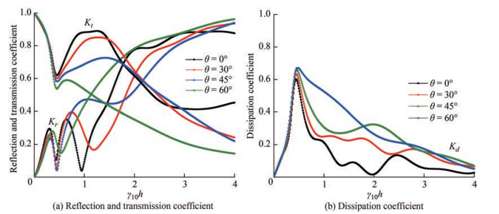
Figure 9 shows the reflection, transmission and dissipation coefficient against the non-dimensional wave number γ10h for different values of angle of incidence. It is observed that as the angle of incidence increases, the reflection coefficient (Figure 9(a)) increases while the transmission coefficient decreases. This could be due to the fact that as the angle of incidence increases, the wave is reflected more rather than passing through the porous structure, resulting in increased reflection and decreased transmission. Further, it is noted that the wave attenuation increases as the angle of incidence increases. The wave dissipation coefficient (Figure 9(b)) attains maximum value within 0.25 < γ10h < 0.75 and thereafter approach to minimum value with the increase in γ10h. The higher wave energy dissipation is noted in the shallow water region and with the change in the angle of incidence the Kd is observed same within 0 < γ10h < 0.5.
5.2.4 Effect of plate length
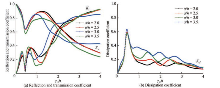
The reflection Kr, transmission Kt and dissipation coefficients Kd (Figure 10) are plotted against the non-dimensional wave number γ10h for different values of plate length a/h. The reflection coefficient (Figure 10(a)) is oberved to increase as the plate length increases up to γ10h = 0.75. Further, it is observed that the reflection coefficient is higher for a/h = 3.0 up to γ10h = 3 and beyond γ10h = 3, the value of Kr is higher for a/h = 3.5 (Figure 10(a)). The wave transmission is observed to reduce as the plate length increases. This may be due to the attenuation of more waves throughout the length of the plate as the plate length increases and hence reducing the transmision coefficient. The wave transmission coefficient is reduced to 0.25 from 1.0 as the plate length increases within 2.0 < a/h1 < 3.5. Thus as the plate length is increased, the energy dissipation coefficient increases, which could be due to increased wave-porous plate interaction. Further, the dissipation coefficient (Figure 10(b)) is noted to be same for all plate lenghts within 0.25 < γ10h < 0.75 and therafter an oscillating decreasing trend is noted for γ10h ≥ 1.0.
5.2.5 Effect of width of fully-extended porous structure
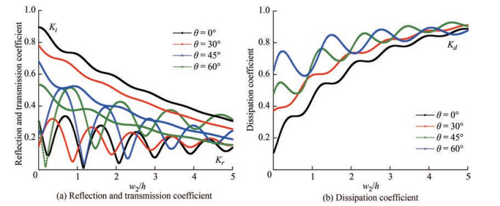
In Figure 11, the reflection, transmission and dissipation coefficient are plotted the against the width of the fully-extended porous structure w2 /h for different angle of incidence. The reflection coefficient (Figure 11(a)) shows an oscillating trend as the width of the fully-extended porous structure increases. In addition, the resonating crest and trough of the reflection coefficient are observed to be decreasing as the width of the fully-extended porous structure increases. It is noted that for normal angle of incidence θ = 0°, the resonating trough of wave reflection coefficient reduces to 0.02 at w2 /h = 1.2. Further, as the width of the fully-extended porous structure increases, the resonating peak and trough increases. It is also observed that the transmission coefficient decreases as the width of the fully extended porous structure increases and the transmission coefficient reduces to 0.1 from 0.55 for θ = 60°. The trend shows the increase in the reflection coefficient and decrease in the transmission coefficient as the angle of incidence increases. The decrease in reflection and transmission coefficients as the width of the fully extended porous structure increases could be due to the wave being damped within the structure, resulting in higher wave energy dissipation (Figure 11(b)). The energy dissipation coefficient shows oscillating trend with the increase in the width of the fullyextended porous structure for various angle of incidence.
5.2.6 Effect of distance between the porous structure and submerged plate
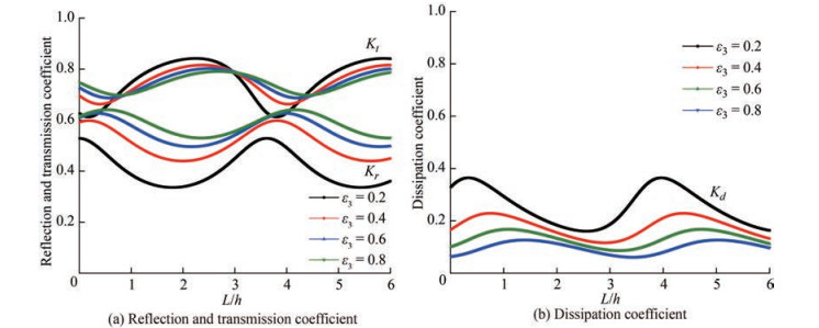
In Figure 12, the reflection, transmission and dissipation coefficient are plotted against the distance between the porous structure and the submerged plate L/h for different angle of incidence. In Figure 12(a), the reflection coefficient shows a resonating trend as the distance between the porous structure and the plate increases. At the resonating crests, the reflection coefficient decreases as the porosity of the fully-extended porous structure increases, while at the resonating troughs, the reflection coefficient increases as the porosity of the fully-extended porous structure increases. The constructive and destructive interferences of the waves cause the resonating patterns to appear. The transmission coefficient, on the other hand, appears to increase as the porosity of the fully extended porous structure increases, both at the resonating peaks and troughs. The resonating pattern could be caused by the waves being trapped in the space between the porous structures. On the other hand, the dissipation coefficient (Figure 12(b)) is observed more for minimum porosity of the fully-extended porous structure. In addition the dissipation coefficient shows maximum value within 0 < L/h < 0.5 and 3.5 < L/h < 4.5.
5.3 Wave force on the structure
The effect of the wave force on the submerged structure, floating plate and fully extended structure is investigated for different physical and geometrical parameters to analyse the effectiveness of the composite breakwater system.
5.3.1 Effect of porosity of fully-extended porous structure
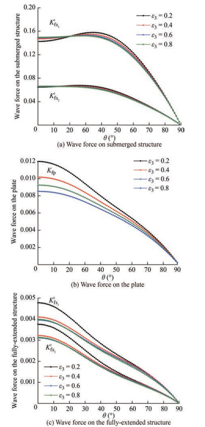
In Figure 13, the wave force on front Kfs11 and back Kfs21 of the bottom-standing porous structure, wave force on the submerged plate Kfp, wave force on front Kfs12 and back Kfs22 of the fully-extended porous structure are plotted against the angle of incidence θ for different values of porosity ε3 of fully-extended porous structure. The porosity of the bottom stanidng porous structure ε1 = 0.3 and submerged porous plate ε2 = 0.1 are kept constant. In Figure 13(a), it is observed that the wave force on the bottom standing porous structure has less effect due to the change in ε3. But the slight variation suggests that when the porosity of fully-extended structure is lower then wave transmission will be less and the wave gets reflected and increases the force on bottom-standing structure. As the porosity of the fully-extended porous structure increases, the wave force on the submerged porous plate decreases (Figure 13(b)). Similarly, in Figure 13(c) as the porosity of the structure increases, the wave force on the front and back of the fully-extended porous structure decreases. This could be due to the fact that as the porosity of the full-extended porous structure increases, waves can easily pass through it, allowing for more transmission and reducing the wave force impact on the structure.
5.3.2 Effect of submergence depth of plate
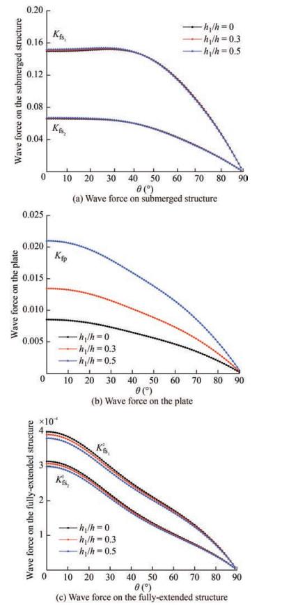
Figure 14 presents the wave force on front Kfs11 and back Kfs21 of the bottom standing porous structure, wave force on the submerged plate Kfp, wave force on front Kfs12 and back Kfs22 of the fully extended porous structure plotted against the angle of incidence θ for different values of submergence depth of plate h1 /h. As the angle of incidence increases, the wave force on the front and back of the bottom-standing porous structure (Figure 14(a)) decreases. Further, as the plate submergence depth increases, the wave force on the front and back of the bottom-standing porous structure does not show much variation. In Figure 14(b), the wave force on the plate decreases as the angle of incidence increases. Similar to Kfs11 and Kfs21, the value of Kfs is maximum for θ = 0°. Figure 14(c) shows that the wave force on the front and back of the fully extended porous structure also decreases as the angle of incidence increases. The wave force on the front and back of the fully-extended porous structure does not differ significantly as the plate submergence depth increases. When compared to porous plates and bottom-standing porous structures, it is seen that the wave forces acting on fully-extended porous structures are substantially lower. This might be because the porous plate and the bottom-standing porous structure help to dissipate wave energy, which further reduces the impact of waves on the fully-extended porous structure.
5.3.3 Effect of width of fully-extended porous structure
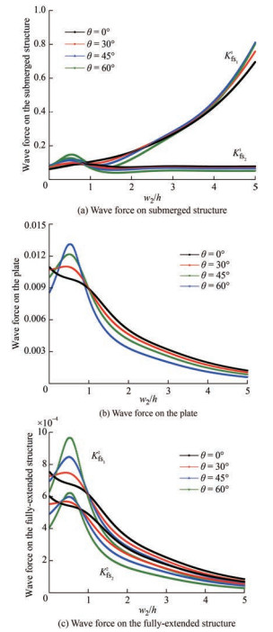
In Figure 15, the wave force on front Kfs11 and back Kfs21 of the bottom-standing porous structure, wave force on the submerged plate Kfp, wave force on front Kfs12 and back Kfs22 of the fully-extended porous structure are plotted against the width of the fully-extended porous structures w2 /h for different values of angle of incidence θ.
In Figure 15(a), it is noted that the wave force on the front of the bottom-standing porous structure increases as the width of the fully-extended porous structure increases for θ = 0°. Then for higher values of angle of incidence, the value of Kfs11 increases and decreases within 0.01 < w2 /h < 1 and afterwards it shows a gradual increase for higher width of fully-extended porous structure. The wave force on the back of the bottom-standing porous structure has a wavy nature within 0.01 < w2 /h < 3. Beyond that, the value of Kfs21 remains constant. In Figure 15(b), the wave force on the plate decreases as the width of the fully-extended porous structure increases for θ = 0° and for greater values of θ, the value of Kfp increases and decreases within 0.01 < w2 /h < 1 and then decreases eventually. The wave force on the front and back of the fully extended porous structure shows a similar trend (Figure 15(c)). It is also noted that within 0.01 < w2 /h < 1, the wave force is higher for higher angle of incidence whereas for w2 /h > 1.0, the wave force is less for higher angle of incidence.
5.3.4 Effect of distance between the porous structure and submerged plate
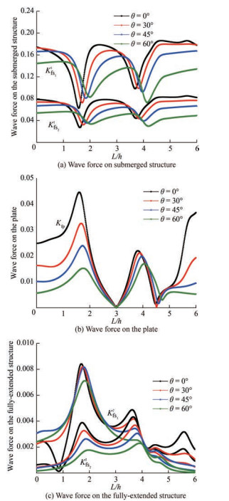
Figure 16 shows the wave force on front Kfs11 and back Kfs21 of the bottom standing porous structure, wave force on the submerged porous plate Kfp, wave force on front Kfs12 and back Kfs22 of the fully extended porous structure against the distance between the porous structure and submerged plate L/h for different values of angle of incidence θ.
In Figure 16(a), the wave force of the front and back of the bottom stadning structure shows a resonating pattern as the distance between the porous structure and the submerged plate increases. It is also observed that the wave force on the bottom-standing porous structure reduces with increase in angle of incidence. In Figure 16(b), the wave force on the sumerged porous plate is observed to increase to a maximum value at L/h = 1.5 and then decreases to almost zero for all values of angle of incidence. Thereafter, it again increases and decreases to almost zero at L/h = 4.5. This may be due to the wave attenuation in the confined region between the porous structure and the submerged plate. In Figure 16(c), the wave force on the front of the fully extended porous structure shows a maximum value at L/h = 0.75 and then decreases as L/h increases. The wave force on the back of the fully-extended porous structure also shows an oscillating trend with increase in L/h. The resonating trend in the wave forces could be due to the trapping of waves in the free space between the submerged plate and porous structure.
6 Conclusions
The wave damping due to the combination of bottom-standing porous structure, submerged horizontal porous plate and fully-extended porous structure is studied using the eigen function expansion method and orthogonal mode-coupling relation. The hydrodynamic coefficients obtained using the numerical investigation are validated using the experimental results. The effect of various physical and geometrical parameters on the wave force on the structure are also analysed for the combined porous structure with the submerged plate. The conclusions drawn from the present study are as follows:
1) The performance of the composite breakwater system is observed better when the plate is on the water surface and the energy damping is maximum at plate submergence depth close to the free-surface. The resonating trend in reflection and transmission is observed for the composite breakwater system which may be the trapping of waves in the confined regions in the porous structure, and may be due to the formation of standing waves in the gaps between the porous structures.
2) The wave reflection is observed higher for the submerged plate at the free surface and the porus structure with less porosity and the transmission coefficient is observed to be low and also the wave energy dissipation high for larger plate lengths.
3) The hydrodynamic coefficients show an oscillating pattern as the distance between the porous structure and the submerged plate L/h varies. So, a suitable value of L/h should be chosen where the transmission coefficient is low and energy dissipation is higher.
4) The increase in width of the fully-extended structure w2/h improves the performance characteristics of the proposed composite breakwater system. Further, it is observed that when w2/h < 1.0, the wave force on the structure is higher. So, it is better to choose w2/h > 1 for the design purpose.
5) The wave force on the structure and wave transmission is higher at lower angle of incidence whereas the reflection coefficient is minimum at θ = 0°. Further, the wave force on the fully-extended structure is reduced significantly with the inclusion of the submerged porous plate and bottom-standing structure for varius submergence depth of the plate.
Acknowledgement: The authors acknowledge Science and Engineering Research Board (SERB), Department of Science & amp; Technology (DST), Government of India for supporting financially under the research Grant No. CRG/2018/004184 and Ministry of Ports, Shipping and Waterways, Government of India through the research Grant No. DW/01013(13)/2/2021.${contentEle.labelText} Nomenclatureb Distance between the porous structure f Linearized friction factor g Accelaration due to gravity h Water depth h1 Submergence depth of plate and bottom-standing porous structure i Imaginary number kjn Wave number in x-direction Kr Reflection coefficient Kt Transmission coefficient Kd Dissipation coefficient Kfs11 Wave force on the front of the bottom-standing porous structure Kfs21 Wave force on the back of the bottom-standing porous structure Kfp Wave force on submerged porous pate Kfs12 Wave force on the front of the fully-extended porous structure Kfs22 Wave force on the back of the fully-extended porous structure l Wave number in z-direction L Distance between the plate and porous structures s Inertial effect of the porous medium w1 Width of the bottom-standing porous structure w2 Width of the fully-extended porous structure γjn Wave number in y-direction εj The porosity of each layer θ Angle of incidence ηj Free surface wave elevation ρ Density of water ω Wave frequency ϕ Velocity potential Competing interest D. Karmakar is an editorial board member for the Journal of Marine Science and Application and was not involved in the editorial review, or the decision to publish this article. All authors declare that there are no other competing interests. -
Table 1 Flume details
Total length (m) 50 Channel length (m) 42 Width (m) 0.74 Channel depth (m) 1.1 Maximum water depth (m) 0.5 Wave flume type Two dimensional Wave Generator Bottom hinged flap type Waves generated Monochromatic type Wave absorber Rubble mound spending beach Range of wave height generation (m) 0.06 – 0.24 Range of wave period generation (s) 1.0 – 3.0 Table 2 Selection of the model scale
Scale Hi (m) T (s) 1 5.4 8 12 1∶10 0.1 0.54 2.53 3.8 1∶20 0.05 0.27 1.79 2.68 1∶30 0.033 0.18 1.46 2.19 1∶40 0.025 0.135 1.26 1.9 Table 3 Structural dimensions of the model (m)
Structural parameters Model dimensions Width Thickness Height/Length Bottom-standing stucture 0.72 0.15 0.25 Submerged plate 0.72 0.002 1.0 Fully extended structure 0.72 0.15 0.5 Table 4 Experimental variables of composite breakwater
Variables Expression Parameter range Wave period (s) T 1.4, 1.6, 1.8, 2.0 Incident wave height (m) Hi 0.06, 0.08, 0.10, 0.12, 0.14 Water depth (m) h 0.45 Angle of wave attack θ 0° Incident wave steepness Hi /gT 2 0.001 5 – 0.006 2 Nomenclature
b Distance between the porous structure f Linearized friction factor g Accelaration due to gravity h Water depth h1 Submergence depth of plate and bottom-standing porous structure i Imaginary number kjn Wave number in x-direction Kr Reflection coefficient Kt Transmission coefficient Kd Dissipation coefficient Kfs11 Wave force on the front of the bottom-standing porous structure Kfs21 Wave force on the back of the bottom-standing porous structure Kfp Wave force on submerged porous pate Kfs12 Wave force on the front of the fully-extended porous structure Kfs22 Wave force on the back of the fully-extended porous structure l Wave number in z-direction L Distance between the plate and porous structures s Inertial effect of the porous medium w1 Width of the bottom-standing porous structure w2 Width of the fully-extended porous structure γjn Wave number in y-direction εj The porosity of each layer θ Angle of incidence ηj Free surface wave elevation ρ Density of water ω Wave frequency ϕ Velocity potential -
Arunachalam VM (1982) Experimental studies on a perforated horizontal floating plate breakwater. Ocean Engineering 9(1): 3545. https://doi.org/10.1016/0029-8018(82)90043-9 Bennett GS, McIver P, Smallman JV (1992) A mathematical model of a slotted wavescreen breakwater. Coastal Engineering 18(3–4): 231–249. https://doi.org/10.1016/0378-3839(92)90021-L Cho IH, Kim MH (2013) Transmission of oblique incident waves by a submerged horizontal porous plate. Ocean Engineering 61: 56–65. https://doi.org/10.1016/j.oceaneng.2012.12.044 Cho IH, Koh HJ, Kim JR, Kim MH (2013) Wave scattering by dual submerged horizontal porous plates. Ocean Engineering 73: 149–158. https://doi.org/10.1016/j.oceaneng.2013.08.008 Dalrymple A, Losada A, Martin PA (1991) Reflection and transmission from porous structure under oblique wave attack. Journal of Fluid Mechanics 224: 625–644. https://doi.org/10.1017/S0022112091001908 Das S, Bora SN (2014) Reflection of oblique ocean water waves by a vertical rectangular porous structure placed on an elevated horizontal bottom. Ocean Engineering 82: 135–143. https://doi.org/10.1016/j.oceaneng.2014.02.035 Dattatri J, Shankar NJ, Raman H (1978) Performance characteristics of submerged breakwaters. Coastal Engineering 130: 2153–2171. https://doi.org/10.1061/9780872621909.132 Dick TM, Brebner A (1968) Solid and permeable submerged breakwaters. Coastal Engineering 72: 1141–1158. https://doi.org/10.1061/9780872620131.072 Goda Y, Suzuki Y (1976) Estimation of incident and reflected waves in random wave experiments. Proceedings of 15th Costal Engineering Conference (ASCE), Honolulu, 828–845. https://doi.org/10.1061/9780872620834.048 Huang LH, Chao HI (1992) Reflection and transmission of water wave by porous breakwater. Journal of Waterway, Port, Coastal and Ocean Engineering 118: 437–452. https://doi.org/10.1061/(ASCE)0733-950X(1992)118:5(437) Isaacson M (1991) Measurement of regular wave reflection. Journal of Waterway, Port, Coastal, Ocean Engineering 117: 553–569. https://doi.org/10.1061/(ASCE)0733-950X(1991)117:6(553) Koley S, Behera H, Sahoo T (2015) Interaction of gravity waves with bottom standing submerged structures having perforated outer-layer placed on a sloping bed. Applied Ocean Research 52: 245–260. https://doi.org/10.1016/j.apor.2015.06.003 Li AJ, Liu Y, Fang H (2021) Novel analytical solutions without finding complex roots for oblique wave scattering by submerged porous/perforated structures. Applied Ocean Research 112: 102685. https://doi.org/10.1016/j.apor.2021.102685 Liu Y, Li Y (2011) An alternative analytical solution for water-wave motion over a submerged horizontal porous plate. Journal of Engineering Mechanics 69: 385–400. https://doi.org/10.1007/s10665-010-9406-8 Losada IJ, Dalrymple RA, Losada MA (1991) Water waves on rown breakwaters. Journal of Waterway, Port, Coastal and Ocean Engineering 119(4): 367–380. https://doi.org/10.1061/(ASCE)0733-950X(1993)119:4(367) Losada IJ, Losada MA, Martin FL (1995) Experimental study of wave induced flow in a porous structure. Coastal Engineering 26: 77–98. https://doi.org/10.1016/0378-3839(95)00013-5 Losada IJ, Silva R, Losada MA (1996) 3-D non-breaking regular wave interaction with submerged breakwaters. Coastal Engineering 28: 229–248. https://doi.org/10.1016/0378-3839(96)00019-1 Madsen (1983) Wave reflection from a vertical permeable wave absorber. Coastal Engineering 7: 381–396. https://doi.org/10.1016/0378-3839(83)90005-4 Mohapatra SC, Sahoo T, Guedes Soares C (2018) Surface gravity wave interaction with a submerged horizontal flexible porous plate. Applied Ocean Research 78: 61–74. https://doi.org/10.1016/j.apor.2018.06.002 Neelamani S, Gayathri T (2006) Wave interaction with twin plate wave barrier. Ocean Engineering 33(3–4): 495–516. https://doi.org/10.1016/j.oceaneng.2005.03.009 Neelamani S, Reddy MS (1992) Wave transmission and reflection characteristics of a rigid surface and submerged horizontal plate. Ocean Engineering 19(4): 327–341. https://doi.org/10.1016/0029-8018(92)90033-Z Patil SB, Karmakar D (2022) Hydrodynamic analysis of floating tunnel with submerged rubble mound breakwater. Ocean Engineering 264: 112460. https://doi.org/10.1016/j.oceaneng.2022.112460 Sollitt CK, Cross RH (1972) Wave transmission through permeable breakwaters. Coastal Engineering 103: 1827–1846. https://doi.org/10.9753/icce.v13.99 Somervell LT, Thampi SG, Shashikala AP (2018) Estimation of friction coefficient of double walled permeable vertical breakwater. Ocean Engineering 156: 25–37. https://doi.org/10.1016/j.oceaneng.2018.02.050 Sulisz W (1985) Wave reflection and transmission at permeable breakwaters of arbitrary cross-section. Coastal Engineering 9: 371–386. https://doi.org/10.1016/0378-3839(85)90018-3 Ting CL, Lin MC, Cheng CY (2004) Porosity effects on nonbreaking surface waves over permeable submerged breakwaters. Coastal Engineering 50: 213–224. https://doi.org/10.1016/j.coastaleng.2003.10.003 Twu SW, Chieu CC (2000) A highly wave dissipation offshore breakwater. Ocean Engineering 27: 315–330. https://doi.org/10.1016/S0029-8018(99)00002-5 Twu SW, Liu CC, Hsu WH (2002) Wave damping characteristics of deeply submerged breakwaters. Journal of Waterway, Port, Coastal and Ocean Engineering 127: 97–105. https://doi.org/10.1061/(ASCE)0733-950X(2001)127:2(97) Venkateswarlu V, Karmakar D (2020) Significance of seabed characteristics on wave transformation in the presence of stratified porous block. Coastal Engineering Journal 62(1): 1–22. https://doi.org/10.1080/21664250.2019.1676366 Venkateswarlu V, Karmakar D (2021) Numerical investigation on the wave dissipating performance due to multiple porous structures. ISH Journal of Hydraulic Engineering 27(S1): 202–219. https://doi.org/10.1080/09715010.2019.1615393 Wang HY, Sun ZC (2010) Experimental study of a porous floating breakwater. Ocean Engineering 37: 520–527. https://doi.org/10.1016/j.oceaneng.2009.12.005 Xie JJ (2022) Long wave reflection by an array of submerged trapezoidal breakwaters on a sloping seabed. Ocean Engineering 252: 111138. https://doi.org/10.1016/j.oceaneng.2022.111138 Yang Z, Yong L, Huajun LI, Anteng C (2017) Oblique wave motion over multiple submerged porous bars near a vertical wall. Journal of Ocean University China 16(4): 568–574. https://doi.org/10.1007/s11802-017-3333-5 Zhu S, Chwang AT (2001) Analytical study of porous wave absorber. Journal of Engineering Mechanics 127: 326–332. https://doi.org/10.1061/(ASCE)0733-9399(2001)127:4(326)


