Numerical Investigation on Different Configurations of Offshore Fish Cages in Submerged Conditions Subjected to Regular Waves
https://doi.org/10.1007/s11804-023-00361-7
-
Abstract
The present research work concerns about the hydrodynamic behaviors of the open net offshore fish cages of single, double and 4-cage systems subjected to regular sinusoidal waves. The open net semisubmersible rigid cage is square in shape and analyzed numerically using ANSYS AQWA software. Frequency and time domain analyses are carried out for each case. The hydrodynamic parameters such as added mass, radiation potential damping, motion responses and mooring line tensions are considered as performance indicators to conclude as the best arrangements among three different cages. The single cage and windward side of all cages exhibit identical performance in all hydrodynamic parameters. The leeward side of each cage shows lesser parametric values than the windward side cages. Based on the performance indicators, it is concluded that the grid system containing four cage arrangements provides better performance than three other cage configurations. An experimental model of 1: 75 scale is fabricated and wave flume studies are conducted to validate the present numerical model. The cage is placed at a water depth of 55 cm and subjected to wave heights of 12 cm and 14 cm with wave periods ranging from 0.8 s to 2.2 s with an interval of 0.2 s are considered. The same wave flume boundary conditions are adopted for numerical simulations and results are in good agreement with experimental work results.-
Keywords:
- Hydrodynamic analysis ·
- Offshore cages ·
- Semisubmersible cages ·
- Cage arrangements ·
- ANSYS AQWA
Article Highlights● Numerical analysis on three different configurations of protoype cages under regular waves been carried out.● Validation of experimental and numerical work for scaled model been presented.● Hydrodynamic characterstics of motion responses and mooring line tension are analysed. -
1 Introduction
Offshore aquaculture is a blooming opportunity in the food consumption industry. Demand for seafood production is increasing due to population growth and healthier diet preferences. As per the Food and Agriculture Organization (FAO) 2020, aquaculture was growing at a steady pace. The overall global fish consumption increased by 3.1% annually from 1961 to 2017, more than twice the population growth rate (1.6%) during the same period (FAO, 2020). It also grew faster than the consumption of alternative animal protein foods (meat, dairy, milk, etc.), increasing by 2.1% per year. In Asia, the production of captured fisheries was about 49.3 million tonnes, whilst aquaculture fisheries were approximately 75.4 million tonnes. The aquaculture production was 7.07% lower than captured fisheries production around worldwide. Meanwhile, the per capita demand for aquaculture food was about 15.7% more than captured fish (UNFPA, 2021). Ninety percent of wild-captured species were already overfished or completely fished out, and there is no way to raise production. As a result, farmed fish is anticipated to surpass caught fish and keep growing impressively in terms of meeting the world's protein needs. China continues to be the world's biggest fish producer, accounting for 35% of global fish production (Svennevig, 2015).
Most marine aquaculture farms are located in shallow and nearshore regions (coastal aquaculture) due to easy accessibility for feed and operations. The nearshore waters are highly occupied for maritime, recreation, and other activities. Environmental degradation due to food and fish waste is the major criticism. Another serious concern is the spread of disease on the native sea life population due to accidental fish escapement, which affects the local ecosystem balance. Offshore farming sites can provide a solution to most of these concerns. Along with a large sea area for cost-effective production, offshore provides better water quality supporting fish health and growth. The offshore en vironment can help to avoid the deposition of fish wastes such as leftover food or fecal matter under cages and to prevent the spread of parasites caused by eutrophication and diseases.
Extensive research was conducted on nearshore cages for net deformation, drag, motion response and mooring line tension. A brief literature review revealed that single, multiple cage grid systems were studied under uniform flow, regular and irregular waves and concluded that the gird system performs better for all conditions. Later, the research focused on exploring the efficacy of offshore cage systems. Studies were conducted on different configurations of shape, size and materials. In terms of large scale, the rigid cages can retain their original geometry and hence no volume of deformation in comparison with flexible fish cages. There is a scope for integrating renewable energy systems with rigid floating cages. Hence, the cages shall be acting as self-sustainable. Also, a rigid cage system is preferable under the circumstances of inadequate lighting, oxygen saturation, a broad range of water temperatures and deeper water depth which may have an impact on the pace of fish growth.
An analytical and experimental study was conducted on a self-submerging cage with a single point mooring system under uniform flow (DeCew et al., 2010). The results indicate that irrespective of net solidity, the cage remained at surfaces for the current velocity of less than 0.75 m/s. The cage exhibited slightly oscillatory behavior for the variation in net solidity of 8.1%, 16% and 23.8% subjected to velocities of 0.08 m/s to 0.6 m/s. The mooring line tension and depth of submergence increased with an increase in current velocity. Later, Kim et al. (2011) developed an algorithm for a self-submerging system with an air control technique and the results were validated with model experiments. The cage automatically submerges below the surface when the incident wave heights exceed the critical wave height and returns to the surface when the wave conditions are normal.
The numerical model was developed using rigid body kinematics and lumped mass method was used to study the behavior of multiple cages (2, 4 cages) under regular sinusoidal waves (Xu et al., 2012). Experimental studies were conducted to validate the numerical method, and results were in good agreement. The mooring cable tension for the two-cage layout is maximal at 0° wave incident angle and lowest at 45°. Also, the study suggested that 45° wave incident angle is preferable for the fish cage and grid mooring system design. Further, multiple (2, 4 cages) arrangements were studied under irregular waves and concluded that 45° wave incident angle should be considered for the design of a grid mooring system (Zhao et al., 2012). Later, the grid system was studied for two different layouts of twin mooring system and orthogonal mooring system for submerged conditions under both waves and currents. It was learnt that the mooring line tension of the single cage was four times greater than the four-cage grid system for the waves combined with currents. Also, it was understood that the orthogonal grid mooring system provides better performance in all environmental conditions than the twin mooring system (Xu et al., 2013).
Zhao et al. (2015) conducted a laboratory test on aquaculture cages with five different configurations under steady currents to study the flow velocity reduction and mooring line tensions. The upstream mooring lines endure most of the external loads on a multiple cage system. The results suggested that 2×4 configurations were best suited economically despite mooring line tensions. The flow velocity reduction increases with an increase in the number of cages and there is not much variation in velocity reduction for different configurations. Also, the results suggested that 2×1 configuration was best for water exchange. A preliminary numerical investigation (Li et al., 2017) was carried out to understand the shape effect on offshore fish cage performance subjected to waves and currents. Both frequency and time domain analyses were carried out to obtain mooring cable tension and global responses. A simplified grid net and current were included in time domain simulations and results were compared. The results indicate that the mooring line tension and drift motions were increased with inclusion of net elements and currents.
Milich and Drimer (2019) developed a novel concept of a flexible semisubmersible cage with a single point mooring system and finite element analysis was carried out using AQUASIM software. The results indicate that the cage retains 70% of its original volume in severe storm conditions. A conventional 3×3 grid system exhibited three times higher mooring line tension than the single point mooring with nine cages in a row. Further, Huang et al. (2020) conducted an experimental study on a scaled model of a vessel shaped offshore cage with a single point mooring system under waves and currents separately. The cage with three different drafts and mooring line lengths were considered. The cage exhibited better performance for wave and current conditions and was suitable to use in practice for large scale models.
A series of physical tank tests were conducted on a scaled model of Oceanfarm1 in pure waves for three different draughts (Yu et al., 2019). A numerical method was developed based on the boundary element method to validate the experimental results and are in good agreement (Liu et al., 2020). The mooring line tension and motion responses decrease with an increase in draughts. Wave steepness significantly influenced the hydrodynamic responses of the cage, whereas wave length and draught had less importance.
A computational fluid dynamic study was performed on the single and multiple cages using porous media model under uniform flow. The results show that the square grid pattern exhibited a significant effect on velocity reduction and staggered pattern shows the best performance in terms of water exchange (Bui et al., 2020). An analysis of COSPAR (COmbines a floating SPAR wind turbine and a fish cage) cages coupled with moorings in the frequency domain and time domain approaches was carried out (Chu and Wang, 2021). Octagonal geometry is similar to Ocean farm-1 and promises enhanced hydrodynamic performance and reduced tension forces in the mooring lines. COSPAR showed better ability to withstand pitching and heaving motions contrary to hydrodynamic action of waves and currents and was less prone to viscous damping.
An analytical model based on linearized water wave theory was created to investigate the dynamic properties of a flexible cylindrical cage. The analytical results are contrasted to numerical SIMA simulations, which are validated with known experimental data (Mohapatra et al., 2021). Further research was conducted, and dynamic characteristics were investigated using a finite element analysis (FEA) technique (Liu et al., 2021). The analytical model shows significant agreement with both SIMA and FEA simulations. The horizontal displacement, acceleration, and force involving various design factors such as cage heights, cage radius, tensile forces, mooring stiffness, and membrane tensions were considered into account. The results show that mooring stiffness and membrane tension increase when horizontal displacement decreases. The cage height and radius are proportional to horizontal displacement. The cylindrical cage performed consistently well in the horizontal wave force analysis.
Researchers have conducted a detailed review of near shore and offshore cage systems (Timmons et al., 1998; Chu et al., 2020; Guo et al., 2020; Xu and Qin, 2020) in the recent past.
The present study describes the numerical study of a submerged offshore cage with three different arrangments. To study the hydrodynamic characteristics, both frequency and time domain analyses are carried out using ANSYS AQWA (ANSYS, 2022). A comparative study is conducted on a scaled model both experimentally and numerically. In this paper, section 2 describes the detailed experimental and numerical work of both model scale and prototype structures. Section 3.1 demonstrates the validation of scaled models and section 3.2 discusses the numerical results of different cage configurations.
2 Experimental work and Numerical simulations
2.1 Model scale studies
The study of experimental models plays a crucial role in coastal engineering problems since they provide insight into the direct interactions between waves and structures. Models of physical systems can be created at different scales (Hughes, 1993). Prior investigation of any physical model, it is essential to determine similitude requirements and decide on a model scale. Models and prototypes can be compared when all factors influencing the phenomenon are proportional. Hughes (1993) suggests that the similitude of model can be established through calibration, differential equations, dimensional analysis, and scale series.
The geometric, kinematic, and dynamic similarity is measured according to the Froude similarity scale of 1∶75. Physical model testing is performed in wave flume laboratory of Department of Water Resources and Ocean Engineering at National Institute of Technology Karnataka. Figure 1 illustrates a two-dimensional wave flume of a length of 50 m, 0.71 m wide, and 1.1 m deep. A bottom hinged flap wave generator can generate regular waves with differing wave heights and periods. The geometric properties of a model scaled square cage are shown in Table 1 for numerical simulation and experimental work. The cage is modelled as hollow circular steel components, which aids in offering buoyancy. The cage comprises four vertical columns, diagonal and radial girders, top and bottom horizontal girders, and four pontoons at each corner of the vertical column. The present investigation employs a diamondmesh knotted high-density polyethylene (HDPE) net, with a net solidity of 0.26. The total mass of the cage with net solidity of 0.26 is about 6.326 kg.
 Figure 1 Schematic diagram of two-dimensional wave flumeTable 1 Geometric properties and wave environmental conditions for square cage
Geometric properties Wave environment conditions Member Diameter (cm) Length (cm) Plate thickness (cm) Wave period (s) Wave height (cm) Pontoon (4) 6.4 3 0.12 0.8 Top horizontal girder (4) 2.5 40 0.12 1.0 Bottom horizontal girders (4) 2.5 40 0.12 1.2 12 Diagonal girders (4) 2.5 50 0.12 1.4 14 Side vertical column (4) 3.2 37 0.12 1.6 Bottom cross girder (4) 2.5 40 0.12 1.8 Top cross girder (4) 0.6 40 0.6 2.0
2.2Heave and tilt sensors are affixed at the top centre of structure to quantify the hydrodynamic responses of heave and pitch motions. Underwater load cells with a 7.35 N capacity are used to measure the anchor line tension. Each testing condition is performed three times, to ensure the repeatability of physical phenomena and the accuracy of the data acquired for the analysis. Figure 1 demonstrates the schematic sketch of flume details and cage arrangements in the flume. The cage is placed at water depth of 55 cm and is subjected to two different wave heights of 12 cm and 14 cm, with periods varying from 0.8 s to 2.2 s with an interval of 0.2 s. Same conditions are reproduced in the numerical simulation. The positioning of the cage in the flume and the numerical simulation model are shown in Figure 2.
 Figure 2 The arrangement of square cage
Net solidity is one of the influencing characteristics which affect the floating fish cage's hydrodynamic properties such as transmission, reflection, energy loss, motion responses, and mooring line tension. A net solidity is exemplified as the ratio between the projected area (AP) covered by the twines and the entire net panel area (A). In this study, a knotted HDPE diamond mesh net is employed, and an empirical formula is used to calculate the net solidity of the current fishing net.
$$ S_{n}=\frac{A_{p}}{A} $$ (1) $$ S_{n}=\left(\frac{2 l_{w} d_{w} \pm\left(d_{w}\right)^{2}}{\left(l_{w}\right)^{2}}\right) $$ (2) where Sn is the solidity ratio, lw is the length of string, and dw is the diameter of the twine. The net solidity is calculated by adding squared diameter of the knotted net and subtracting the squared diameter of a knotless net. To reduce complexity and simulation runtime, a knotless diamond mesh net is chosen for numerical simulation instead of a knotted HDPE diamond mesh net for experimental investigation (Figure 3).
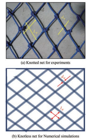 Figure 3 The net panel configuration for both experimental and numreical work
2.2 Numerical simulation of prototype cage
A numerical simulation is carried out using ANSYS AQWA software for the three different cage configurations such as Single, double and four-cage systems.
2.2.1 Methodology of numerical work
The numerical simulation is based on a linear wave, Morison and Stokes second order theories.
The water surface elevation can be expressed with a fixed reference axis.
$$ \zeta=a_{w} \mathrm{e}^{\mathrm{i}[-\omega t+k(X \cos \chi+Y \sin \chi)+\alpha]} $$ (3) where is aw wave amplitude, ω wave frequency, k is wave number, χ is propagating wave direction, and α is wave phase.
The velocity potential function at a particular location of X = (X, Y, Z) can be expressed as
$$ \varnothing_{1}[X, t]=\varphi_{1}[X] \mathrm{e}^{-\mathrm{i} \omega t} $$ (4) $$ \varnothing_{1}[X, t]=-\frac{\mathrm{i} g a_{w} \cosh [k(Z+d)]}{\omega \cosh (k d)} \mathrm{e}^{\mathrm{i}[-\omega t+k(X \cos \chi+Y \sin \chi)+\alpha]} $$ (5) The linear dispersion relation for a free surface condition is represented as
$$ v=\frac{\omega^{2}}{g}=k \tanh (k d) $$ (6) where d is water depth, and g is acceleration due to gravity.
● Linear potential theory:
$$ \varnothing(X, t)=a_{w} \varphi(X) \mathrm{e}^{-\mathrm{i} \omega t} $$ (7) where ∅ is velocity potential, aw is wave length, ω is wave frequency, and X is isolated space term.
● Morison element forces:
$$ \mathrm{d} F=\frac{1}{2} \rho D C_{d}\left|u_{f}-u_{s}\right|\left(u_{f}-u_{s}\right)+\rho A C_{m} \dot{u}_{f}-\rho A\left(C_{m}-1\right) $$ (8) where Cd is drag coefficient, D is characteristic drag diameter, uf is fluid particle velocity_transverse direction, us is structure velocity_transverse direction, Cm is coefficient of inertia and A is cross-sectional area.
● Stokes second order theory:
$$ \begin{gathered} \varnothing=\varepsilon \varnothing^{(1)}+\varepsilon^{2} \varnothing^{(2)}+\mathrm{O}\left(\varepsilon^{3}\right) \\ \zeta=\zeta^{(0)}+\varepsilon \zeta^{(1)}+\varepsilon^{2} \zeta^{(2)}+\mathrm{O}\left(\varepsilon^{3}\right) \\ X=X^{(0)}+\varepsilon X^{(1)}+\varepsilon^{2} X^{(2)}+\mathrm{O}\left(\varepsilon^{3}\right) \end{gathered} $$ (9) where ε→0, ∅ is velocity potential function, ζ is wave elevation function, X is position of point on structure. The superscript (0) denotes the static values, and superscripts (1) and (2) indicate the first and second order variations with respect to the perturbation parameter.
 Figure 4 Methodology of present numerical study using ANSYS software
2.2.2 Geometry of cage
The present cage is classified as a semisubmersible cage, which can be immersed to a required depth by filling ballast tanks and it can be fully submerged in extreme weather conditions to avoid the damage of structure. Since it is an offshore fish cage, the water depth is kept at 150 m. The cage height is considered as 30 m for normal operation. All cage truss members are hollow cylindrical steel sections, which are simple to employ as ballast or storage space and provide the required buoyancy. Still water level is maintained across the horizontal plane of the top horizontal girders. Circular structures are most preferable for offshore installation because of the symmetric action of wind, wave and current actions. But these large curved elements are difficult to fabricate and install. Hence, the performance of an alternate design of square cage is analysed here. The geometric parameters, dimensions of the single cage are provided in Table 2 and the schematic diagram is shown in Figure 5.
Table 2 Geometrical parameters of the fish cagePart Member No. of members Diameter (m) Length (m) Plate thickness (m) Pontoons Pontoon 4 4.76 2.25 0.02 Cage Top horizontal girder 4 1.875 30 0.02 Bottom horizontal girders 4 1.875 30 0.02 Diagonal girders 4 1.875 37.5 0.02 Side vertical column 4 2.4 27.75 0.02 Bottom cross girder 2 1.875 30 0.02 Top cross girder 2 0.45 30 0.02  Figure 5 Schematic diagram-showing dimensions of single cage
The cage provides an internal space of 30 m×30 m and a height of 27.75 m with 22.5 m of submerged depth. The schematic diagram of the multiple cage arrangement is given in Figure 6.
 Figure 6 ANSYS models showing three different configurations and notations
 Figure 7 Equivalent net for numerical simulations
2.2.3 Mooring system and bridle lines
Large offshore fish cages need multiple mooring lines in order to be secured in position. The installation of the mooring lines is difficult and leaves a significant benthic imprint. Furthermore, due to its nonlinear behaviour, mooring line complicate the structure con fi gurations and dynamic response analysis. The mooring system consists of four non-linear catenary lines for each cage. Each mooring line is connected to the bottom of the pontoons with a 90° angle between each two lines which would prevent the interference between lines and cage structure motions. Wherever possible, the mooring lines are provided such that the direction of wave propagation is 45° with the mooring lines. But, the angles may vary for the intermediate connections in a multiple cage system due to space limitations. For the mooring line, a non-linear catenary chain with a diameter of 84 mm is used, and a truncated chain length of 140 m is given to allow the cages to move freely. The anchor for the fish cage is presumably set on the seabed (Scott and Muir, 2000). The properties and specifications of the mooring lines are considered as per DNVGL rules and codal provisions (DNV GL, 2017a; 2017b). Table 3 shows the mooring line specifications considered for the present pilot study. Bridle lines connect the cages each other in multiple cage systems and are similar to the catenary cable used for mooring the cages to the sea bed. The length of these lines are kept at 20 m, which allows the cages to move freely without colliding with each other while preventing them from drifting.
Table 3 Mooring line specificationsAnchor line classification Stud link chain NV K3, Diameter 84 mm Density of anchor line (kg/m) 152 Cross-sectional area (m2) 0.011 Youngs modulus (N/m) 5.6×10¹⁰ Drag coefficient (Transverse) 2.6 Drag coefficient (Longitudinal) 1.4 Depth of fairleads below SWL (m) 27.188 2.2.4 Solidity ratio
The total forces (static and dynamic) on the net elements must be considered in hydrodynamic analysis. Because of the large number of net elements required for meshing and reducing computational time, the equivalent net (square mesh) is adopted, modelled by built-in Morison elements (Li and Ong, 2017; Dou, 2018). The equivalent net is designed in such a way that the hydrodynamic forces on both the original and equivalent net are the same. Even though the dimensions changes, the forces acting on both nets are identical. The solidity ratio of net is considered as 0.26, by assuming an equivalent twin length, lw=5 m and the equivalent diameter, dw=0.65 m, is determined.
$$ d_{w}=\frac{S_{n} \cdot l_{w}}{2} $$ (10) 2.2.5 Meshing details of each model
A hybrid model combines panel elements and Morison tubular elements is used for numerical modeling. The top girder and bottom pontoons are panel elements, and the remaining members are Morison tubular elements. The meshing detail of each cage is presented in Table 4.
Table 4 Meshing details of each cage configurationConfiguration Mesh size (m) No. of elements No. of nodes Single cage 0.2 23 695 25 016 Double cage 0.4 29 397 31 546 Four cages 0.8 28 362 37 006 A set of regular wave input data to be used in ANSYS AQWA for analysis is given in Table 5.
Table 5 Hydrostatic properties of cage modelHydrostatic properties of cage m2odel Wave parameters for modelling Parameters Values Time period (s) Wave height (m) Mass (t) 707 6.92 Centre of gravity (m) −13 8.66 Centre of buoyancy (m) −15 10.39 Metacentric height (m) 20.65 12.12 6 Water plane area (m2) 280.5 13.85 Volumetric displacement (m3) 1 753.65 15.58 Natural frequency (Hz)-Heave 0.16 17.32 Natural frequency (Hz)-Pitch 0.12 19.05 3 Results and discussion
High energy sea states induce uncertain translational and rotational motion responses, such as heave, roll, and pitch of floating structures, which are crucial to structural integrity as well as safety regulations. However, roll is insignificant according to the assumption of co-ordinate axis in the simulation. Hence, the present study focuses on the pitch and heave motions of hydrodynamic responses.
3.1 Validation of numerical models
The performance of 1∶75 scaled numerical models is validated with experimental results of motion responses and mooring line tensions, which are depicted in Figure 8. Two different wave heights of 12 cm and 14 cm with eight different wave periods (0.8 s to 2.2 s) with an interval of 0.2 s are considered. To minimize the similitude error, same boundary conditions and wave characteristics are considered for both experimental work and numerical simulations. Figures 8(a) and 8(b) show that the cage exhibits a maximum heave motion of 70 mm in experimental work and 80 mm in numerical work subjected to wave conditions of wave period, T = 1.4 s and wave height, H = 12 cm, 14 cm. Figures 8(c) and 8(d) represent the cages' pitch motions and it is observed that maximum response is in the range of 10°–16° for both wave heights. It is understood that the mooring line tension of the numerical model is greater than the experimental results due to linear and flexible nature of cable. The mooring line tension of seaward cables indicate (Figures 8(e) and 8(f)) that tension increases with an increase in wave periods. A similar trend is obtained for the leeward side cables. However, cable tension on the seaward side is always greater. A peak mooring line tension of 4 kN–5 kN was obtained for seaward side cables, whilst 3 kN – 4 kN for leeward side cables is observed. The numerical model overestimates both motion responses and mooring line tension by 5% –15% compared to experimental results. Besides these minimal differences, the present numerical model shows better performance for all wave conditions considered.
 Figure 8 Validation of numerical scaled model results with experimental work
3.2 Numerical simulation of prototype
The scaled numerical model of 1∶75 is validated with experimental work and the same simulation methodology is adopted for three different prototype cages.
3.2.1 Added mass
Figure 9 shows added mass of the prototype cages for the frequency range between 0.016 and 0.61 Hz which is analysed in free-floating conditions. The results indicate that the number of cages and their configuration has no major effects on the added mass distribution with respect to Frequency. In a multiple cage system, added mass of individual cages showed insignificant effects since all the cages are replica of each other. At low frequencies i.e., upto resonance condition, a steady increase in added mass in pitch and a steady decrease in heave are observed. Beyond the excitation of f/f1=3, the mass of the multi cage configurations deviates from that of a single cage. Also, multi cages show reduced added mass upto a frequency of 0.52 Hz (f/f1 = 4.3) pitch response. A leeward side unit (2C4) reaches negative added mass due to couple effect of heave and pitch motions. A spike in heave added mass indicates considerable fluid acceleration at a frequency ratio of 3.6. For submerged bodies, the added mass may become negative when the depth of submergence is greater than the width and due to free-surface effects which are main causes of negative added mass. In such cases, near-resonant Frequency standing waves may occur above the cut water plane accounting for the rapid changes noticed in both added mass and damping.
 Figure 9 Added mass of prototype cages
3.2.2 Radiation damping
Figure 10 exhibits the radiation potential damping of heave and pitch motions. There is a meager variation in radiation potential of heave motion for all frequencies considered. The four-cage structure shows negative radiation damping at a frequency ratio of 3.63 or an excitation frequency of 0.58 Hz. The single cage structure shows the highest radiation potential damping in pitch motion at higher frequencies ratio between 3 and 4. The heave excitation force is associated only with the flow in the near free surface region, and the resulting pressure acts on the square's top face. The presence of a moonpool leads to the potential risk for internal resonances, which will significantly change the behavior of the hydrodynamic coefficients of additional mass and damping. The spiky behavior in added mass and radiation damping is due to the moonpool effect or the "trapped-mode" frequency of multiple bodies. Trapped mode is a phenomenon, where the added mass is infinite with no wave radiation and dissipation. There will be a drastic change in hydrodynamic behaviors of structure for adjacent to these trapped mode frequencies.
 Figure 10 Radiation damping of cages
3.2.3 Response amplitude operator (RAO) for cages without mooring
The variation of heave and pitch RAOs with frequency ratio (f/f1) is depicted in Figure 11. All the cages in different arrangements followed the same trend and the variation is insignificant in both heave and pitch RAOs. Both seaward side of each cage (2C1, 4C1, 4C3) and leeward side of the cages (2C2, 4C2, 4C4) show similar behavior. RAOs are increasing with increase in frequencies and reach peak value near natural Frequency. Once the peak obtains, the responses decrease as the excitation frequency increases and all the cages exhibit the same behavior.
 Figure 11 RAO for heave
3.2.4 Actual responses of cages
Actual responses from ANSYS AQWA for the heave motion in both frequency and time domain analyses are almost similar for all the configurations of cage system as shown in Figure 12. The trend indicates that heave motion increases with increase in Frequency and reaches maximum. Similarly, the pitch motion increases with Frequency and reaches maximum near the structure's natural Frequency, then reduces as the excitation frequency decreases. The downstream cages show slightly reduced responses due to the shielding effect from upstream cages. The two-cage structure performs better in heave motion whereas four cage structure performs better in pitch response. There is no notable difference in the frequency domain results (Figure 11) and time domain analysis (Figure 12). It is expected that the mooring lines reduce the responses. But at the near resonant regions an unexpected increase in responses are noticed in time domain in comparison with frequency domain and the responses enhanced by two times of results obtained from frequency domain analysis. The significant oscillatory motion of cages may result in flow separation in the resonant band's proximity, which affects the fluid's damping nature. In addition, the dynamic response of the cage structure subjected to wave action changes from linear to nonlinear. Hence, establishing responses may be complicated, and the model response becomes unpredictable.
 Figure 12 Actual responses
3.2.5 Mooring line tension
The upstream and downstream cable tensions in single cage and double cage configurations are plotted in Figure 13 subjected to incident wave height of 6 m and eight discrete wave periods (Table 5). The upstream cable tensions are higher than the downstream cable tensions for all three cage configurations considered. The double configuration's maximum tension load differs by about 30% compared to corresponding single cage mooring lines. Figure 13(c) shows the upstream (seaward) and downstream (leeward) mooring line tension for the four-cage configuration. The upstream cables take larger cable tension than the downstream cables as the waves hit them first and move cages towards downstream. It shows that the upstream cables at the corners of the cage endure highest tension followed by the upstream intermediate cable. Similar trend is visible in downstream cage cables as well. At resonance excitation (f=f1) of 0.072 Hz, the tensile force in the seaward cables is about 225 kN for single cage system. However, at resonance conditions, the tensile force is observed to be about 275 kN for double cage system. From double cage system, it is learnt that the maximum tensile force is observed to be about 301 kN and 288 kN in the seaward and leeward cables, respectively. Also, it is observed that mooring lines endure maximum tensile force under regular wave characteristics of 0.064 Hz and wave height of 6 m. It is understood that the seaward side mooring line tensions are higher compared to the leeward side. A maximum tensile force of 301 kN is observed at off resonance condition (f = 0.082 Hz) in the seaward cable, the same as observed for the two cage systems. Also, the maximum force of 232 kN is observed at leeward cable at far resonance condition of f = 0.14 Hz.
 Figure 13 Mooring line tension in the seaward cables and leeward cables of single and two cage configurations
In general, the upstream mooring line tension increases as the number of cages increases. The downstream line tension is higher for double cage configurations in comparison with other two configurations. The end most mooring lines (main lines) at 45° take more tension than the intermediate/Bridle lines in both double and 4-cage systems. Even though the seaward main mooring line tension is high in 4-cage system, the analysis of performance indicators such as hydrodynamic coefficients, RAOs of pitch and heave, and tensile force in intermediate lines reveal that 4-cage system is a better configuration in considering feasibility and accessibility criteria.
4 Conclusions
A numerical analysis is carried out using ANSYS AQWA to explore the response behaviour of prototype cage configurations namely single cage, double cage and 4-cage arrangements and their effects on the mooring line tensions.
Numerical simulations of the prototype have led to the following conclusions.
1) As a result of the shielding effect of the upstream side, cages installed on the downstream side show better responses to wave action.
2) The single cage configuration has higher added mass than the multiple cages in heave and pitch motions.
3) The upstream mooring line tension increases as the number of cages increases. However, there is considerable reduction of tensile force (10% ‒ 30%) in the downstream mooring lines.
4) Four-cage configuration is found to be an optimum configuration among the three configurations are analysed.
The numerical simulation is validated with scaled physical model of 1∶75 and the performance indicators results are in good agreement with experimental work. However, the present numerical model overestimates the motion responses of physical model by 5%‒15%. The mooring line tension for the windward and leeward sides shows good agreement and overestimates by 5%‒10% compared to physical test results.
In the present numerical simulation, the linearized drag for the structure is not available in regular wave conditions. However, it is available for irregular wave conditions. Future studies will be conducted considering different wave heights, submergence depths and irregular waves. In a multicage system, the cable tension of intermediate/bridle lines shall be considered apart from main mooring lines.
Competing interest The authors have no competing interests to declare that are relevant to the content of this article. -
Figure 1 Schematic diagram of two-dimensional wave flume
Figure 2 The arrangement of square cage
Figure 3 The net panel configuration for both experimental and numreical work
Figure 4 Methodology of present numerical study using ANSYS software
Figure 5 Schematic diagram-showing dimensions of single cage
Figure 6 ANSYS models showing three different configurations and notations
Figure 7 Equivalent net for numerical simulations
Figure 8 Validation of numerical scaled model results with experimental work
Figure 9 Added mass of prototype cages
Figure 10 Radiation damping of cages
Figure 11 RAO for heave
Figure 12 Actual responses
Figure 13 Mooring line tension in the seaward cables and leeward cables of single and two cage configurations
Table 1 Geometric properties and wave environmental conditions for square cage
Geometric properties Wave environment conditions Member Diameter (cm) Length (cm) Plate thickness (cm) Wave period (s) Wave height (cm) Pontoon (4) 6.4 3 0.12 0.8 Top horizontal girder (4) 2.5 40 0.12 1.0 Bottom horizontal girders (4) 2.5 40 0.12 1.2 12 Diagonal girders (4) 2.5 50 0.12 1.4 14 Side vertical column (4) 3.2 37 0.12 1.6 Bottom cross girder (4) 2.5 40 0.12 1.8 Top cross girder (4) 0.6 40 0.6 2.0
2.2Table 2 Geometrical parameters of the fish cage
Part Member No. of members Diameter (m) Length (m) Plate thickness (m) Pontoons Pontoon 4 4.76 2.25 0.02 Cage Top horizontal girder 4 1.875 30 0.02 Bottom horizontal girders 4 1.875 30 0.02 Diagonal girders 4 1.875 37.5 0.02 Side vertical column 4 2.4 27.75 0.02 Bottom cross girder 2 1.875 30 0.02 Top cross girder 2 0.45 30 0.02 Table 3 Mooring line specifications
Anchor line classification Stud link chain NV K3, Diameter 84 mm Density of anchor line (kg/m) 152 Cross-sectional area (m2) 0.011 Youngs modulus (N/m) 5.6×10¹⁰ Drag coefficient (Transverse) 2.6 Drag coefficient (Longitudinal) 1.4 Depth of fairleads below SWL (m) 27.188 Table 4 Meshing details of each cage configuration
Configuration Mesh size (m) No. of elements No. of nodes Single cage 0.2 23 695 25 016 Double cage 0.4 29 397 31 546 Four cages 0.8 28 362 37 006 Table 5 Hydrostatic properties of cage model
Hydrostatic properties of cage m2odel Wave parameters for modelling Parameters Values Time period (s) Wave height (m) Mass (t) 707 6.92 Centre of gravity (m) −13 8.66 Centre of buoyancy (m) −15 10.39 Metacentric height (m) 20.65 12.12 6 Water plane area (m2) 280.5 13.85 Volumetric displacement (m3) 1 753.65 15.58 Natural frequency (Hz)-Heave 0.16 17.32 Natural frequency (Hz)-Pitch 0.12 19.05 -
ANSYS (2022) ANSYS AQWA. Release 2021 R1, help system, AQWA user manual, ANSYS Inc Bui CM, Ho TX, Khieu LH (2020) Numerical study of a flow over and through offshore fish cages. Ocean Eng 201: 107140. https://doi.org/10.1016/j.oceaneng.2020.107140 Chu YI, Wang CM (2021) Design development of porous collar barrier for offshore floating fish cage against wave action, debris and predators. Aquac Eng 92: 102137. https://doi.org/10.1016/j.aquaeng.2020.102137 Chu YI, Wang CM, Park JC, Lader PF (2020) Review of cage and containment tank designs for offshore fish farming. Aquaculture 519: 734928. https://doi.org/10.1016/j.aquaculture.2020.734928 DeCew J, Tsukrov I, Risso A, Swift MR, Celikkol B (2010) Modeling of dynamic behavior of a single-point moored submersible fish cage under currents. Aquac Eng 43(2): 38–45. https://doi.org/10.1016/j.aquaeng.2010.05.002 DNV GL (2017a) Structural design principles. Part 3 Chapter 3, DNV GL DNV GL (2017b) Offshore standard: Position mooring. DNV GL Dou R (2018) Numerical modeling and analysis of semi-submersible fish-cage. Master thesis, Norwegian University of Science and Technology, Trondheim, 21–23 FAO (2020) The state of world fisheries and aquaculture. Food and Agriculture Organization Guo YC, Mohapatra SC, Guedes Soares C (2020) Review of developments in porous membranes and net-type structures for breakwaters and fish cages. Ocean Eng 200: 107027. https://doi.org/10.1016/j.oceaneng.2020.107027 Huang XH, Liu HY, Hu Y, Yuan TP, Tao QY, Wang SM, Liu ZX (2020) Hydrodynamic performance of a semi-submersible offshore fish farm with a single point mooring system in pure waves and current. Aquac Eng 90: 102075. https://doi.org/10.1016/j.aquaeng.2020.102075 Hughes SA (1993) Physical models and laboratory techniques in coastal engineering. Vol. 7, Advanced Series on Ocean Engineering, World Scientific, Singapore. https://doi.org/10.1142/2154 Kim TH, Yang KU, Hwang KS, Jang DJ, Hur JG (2011) Automatic submerging and surfacing performances of model submersible fish cage system operated by air control. Aquac Eng 45(2): 74–86. https://doi.org/10.1016/j.aquaeng.2011.07.003 Li L, Jiang ZY, Ong MC (2017) A preliminary study of a vessel-shaped offshore fish farm concept. International Conference on Offshore Mechanics and Arctic Engineering, Trondheim. https://doi.org/10.1115/OMAE2017-61665. Li L, Ong MC (2017) A preliminary study of a rigid semi-submersible fish farm for open seas. Offshore Geotechnics, Torgeir Moan Honoring Symposium, American Society of Mechanical Engineers, Trondheim. https://doi.org/10.1115/OMAE2017-61520. Liu HF, Bi CW, Zhao YP (2020) Experimental and numerical study of the hydrodynamic characteristics of a semisubmersible aquaculture facility in waves. Ocean Eng 214: 107714. https://doi.org/10.1016/j.oceaneng.2020.107714 Liu Z, Mohapatra SC, Guedes Soares C (2021) Finite element analysis of the effect of currents on the dynamics of a moored flexible cylindrical net cage. J Mar Sci Eng 9(2): 1–18. https://doi.org/10.3390/jmse9020159 Milich M, Drimer N (2019) Design and analysis of an innovative concept for submerging open-sea aquaculture system. IEEE J Ocean Eng 44(3): 707–718. https://doi.org/10.1109/JOE.2018.2826358 Mohapatra SC, Bernardo TA, Guedes Soares C (2021) Dynamic wave induced loads on a moored flexible cylindrical net cage with analytical and numerical model simulations. Appl Ocean Res 110: 102591. https://doi.org/10.1016/j.apor.2021.102591 Scott DCB, Muir JF (2000) Offshore cage systems: A practical overview. In Mediterranean Offshore Mariculture, Options Méditerranéennes: Série B. Etudes et Recherches, eds. Basurco B. and Muir J. Zaragoza, CIHEAM, 79–89. http://om.ciheam.org/om/pdf/b30/00600651.pdf Svennevig N (2015) Prospects and challenges in sea cage farming in tropical Asia. 5th International Symposium on Cage Aquaculture in Asia, Kochi, India Timmons MB, Summerfelt ST, Vinci BJ (1998) Review of circular tank technology and management. Aquac Eng 18(1): 51–69. https://doi.org/10.1016/s0144-8609(98)00023-5 UNFPA (2021) UNFPA global results. Available from https://www.unfpa.org/data/results [Accessed on May 05, 2022] Xu TJ, Dong GH, Zhao YP, Li YC, Gui FK (2012) Numerical investigation of the hydrodynamic behaviors of multiple net cages in waves. Aquac Eng 48: 6–18. https://doi.org/10.1016/j.aquaeng.2011.12.003 Xu TJ, Zhao YP, Dong GH, Li YC, Gui FK (2013) Analysis of hydrodynamic behaviors of multiple net cages in combined wave-current flow. J Fluids Struct 39: 222–236. https://doi.org/10.1016/j.jfluidstructs.2013.02.011 Xu Z, Qin H (2020) Fluid-structure interactions of cage based aquaculture: From structures to organisms. Ocean Eng 217: 107961. https://doi.org/10.1016/j.oceaneng.2020.107961 Yu S, Li P, Qin H, Xu Z (2019) Experimental investigations on hydrodynamic responses of a semi-submersible offshore fish farm in waves. 14th ISOPE Pacific/Asia Offshore Mech Symp PACOMS 2020, 373–380 Zhao YP, Xu TJ, Bi CW, Dong GH, Liu SC (2012) The numerical simulation of hydrodynamics of fishing net cage. Hydrodynamics-Theory and Model, InTech, Shanghai, China, 287–291 Zhao YP, Bi CW, Chen CP, Li YC, Dong GH (2015) Experimental study on flow velocity and mooring loads for multiple net cages in steady current. Aquac Eng 67: 24–31. https://doi.org/10.1016/j.aquaeng.2015.05.005