-
Abstract
In this paper, the scale effect of Kappel tip-rake propellers with different end plate designs was studied using computational fluid dynamics. Given the base size of the mesh and the appropriate numerical model for the determined simulation, the open-water performance of three Kappel propellers with different bending degrees of the end plate at different scales was calculated. Comparing the scale effect of these propellers, the scale effect of the torque coefficient of a Kappel propeller is more intense than that of the conventional propeller. In addition, the scale effect of the torque coefficient is strong when the bending degree of the end plate increases, dwarfing the scale effect on the thrust coefficient. Following the research on the scale effect of the wake field for the Kappel propeller, the laws that reveal the influence of the scale on the wake field were summarized; that is, the high-speed zone in the wake relatively expands with the increase of the scale in company with a trend of tip cross flow. The research reveals the basic variation trend and rule of the open-water performance and wake distribution for the Kappel propeller under different scales within the Reynolds number range of 4.665×10⁵−8.666×10⁷ considering γ transition, as well as the characteristic differences between the Kappel propellers with different end plate designs, which will be of great significance to its optimization design and application to marine vehicles of different scales.Article Highlights• In order to assess the scale effect of Kappel propeller and the influence of the end plate bending degree on the scale effect, three Kappel propellers with different end plate designs were constructed.• 4-order B-spline scheme was applied to vary the blade tip rake distribution for the three Kappel propellers.• γ transition model was considered during the simulation analysis within the Reynolds number range of 4.665×10⁵–8.666×10⁷.• The scale effect on the open-water performance, wake distribution, tip vortex distribution and pressure distribution of each Kappel propeller was studied and compared. -
1 Introduction
Given the ultimate pursuit of performance and the increasingly diverse application, some special propellers have emerged, such as ducted propellers, high-skew propellers (HSPs), and tip-rake propellers (TRPs). The progress of the manufacturing industry has solved the manufacturing problems of special propellers and promoted their applicability. In meeting the requirement of vehicles with different sizes, the scale effect of special propellers must be studied.
The research target of this paper is Kappel TRP, whose blade tip is bent toward the suction side of the blade surface. On the contrary, contracted loaded tip (CLT) propellers bend toward the pressure surface. The bent part of the blade tip is called the end plate, which can prevent the fluid around the pressure surface at the blade tip from flowing back to the suction side, thereby reducing the strength of the blade tip vortex and improving the efficiency of the propeller.
At present, research on the scale effect of conventional ordinary propellers is relatively thorough, and many empirical formulas have emerged to predict the scale effect of propellers, such as the ITTC1978 method, strip method (Praelke, 1994), and βi method (Helma, 2015). Among these methods, the correction method (Kuiper, 1992) proposed by ITTC1978 is the most classic, which recommends geometric parameters at 0.75 of the radius of the propeller blade section to estimate the effect of Reynolds number on the open-water performance of the propeller. In recent years, few studies have been conducted on the scale effect of conventional propellers. Some scholars tried to optimize empirical formulas based on different methods (Yao and Zhang, 2018; Streckwall et al., 2013; Helma et al., 2018; Helma, 2016).
Computational fluid dynamics (CFD) is a commonly used tool for studying the scale effect of special propellers. Bhattacharyya et al. (2016a) applied the CFD method to simulate the performance of two ducted propellers and then predicted and summarized the impact of scale changes on the thrust coefficient and torque coefficient. Furthermore, Bhattacharyya et al. (2016b) considered the transition phenomenon at the model scale and found that the influence of the scale effect on the ducted propeller depends on the pitch and load factor of the propeller, whereas the influence of the duct on the scale effect is minor. Bhattacharyya et al. (2015) comparatively analyzed the scale effect of a controllable pitch propeller operating inside different ducts and showed that the scale effect on open-water characteristics is in the same range for all types of ducts. Abdel-Maksoud et al. (2003) analyzed the flow velocity in the nozzle of a real scale, which is comparatively higher than that of the model scale, leading to a progress of the nozzle thrust and a reduction of the propeller torque.
Chen et al. (2018) compared two scales of HSP E1619 based on the RANS method, and the open-water performance at a given advance speed was obtained on the basis of experimental data, which showed good agreement. Krasilnikov (2009) focused on the influence of skew on the scale effect by changing the skew distribution under the same disk area ratio and concluded that the scale effect of a propeller is related not only to the friction resistance of the blade but also to the pressure distribution on the blade surface. Liu et al. (2021) applied an unsteady Reynolds-averaged Navier-Stokes (URANS) method coupled with the dynamic overset grid approach to the open-water simulation of propeller E1619 and found that the thrust and torque of the propeller grow with the scale because of the boost of pressure component. Moreover, the pressure on the suction side near the trailing edge decreases with the increase of scale.
With regard to the TRP, Sánchez-Caja et al. (2014) focused on the relationship between the scale effect of the CLT propeller and the shape of the end plate, changed the parameters such as the rake and skew of the end plate, and analyzed the influence of different end plates on the openwater performance and the scale effect on the radial distribution of blade circulation through CFD. Sun et al. (2020) used direct numerical simulation (DNS) method to analyze the open-water hydrodynamic performance of propeller P1727 and the variation of propeller wake distribution at various scales in detail, revealing the relationship between the load on the blade and the propeller wake. Dong et al. (2018) assessed the difference of two-dimensional plane stress at different radii of propeller P1727 and found that the scale effect of the TRP on the thrust is as important as that on the torque. Lungu (2019) also adopted DNS method to analyze the thrust coefficient distribution and vortex structure of the propeller at model and real scales and offered suggestions on propeller simulation.
Cheng et al. (2010) compared the scale effect of the Kappel propeller with regard to open-water performance with that of a conventional propeller designed using the same requirements and concluded that the scale effect of the Kappel propeller is more intense than that of the conventional propeller. Peravali et al. (2016) compared the difference between the RANS method and the ITTC1978 method to predict the scale effect of the Kappel propeller and evaluated the applicability of the ITTC1978 method.
The scale effect of the propeller is reflected in the interaction between the propeller and the vehicle. Choi et al. (2014) explored the relationship of the scale effect of the pod propeller with Reynolds number and load and found that the interaction between the propeller and the pod is the key factor. Sun et al. (2018) used RANS and VOF methods to simulate the self-propulsion point of a container ship and found that the wake fraction and velocity near the self-propulsion point are affected by the scale effect. Ueno et al. (2019) studied the difference between the performance of the propeller and the hull at model and real scales under the condition of a self-propulsion test with irregular waves and winds and found that low- and high-frequency factors can affect the prediction of the scale effect. Sun et al. (2021) predicted the influence of the scale effect on the unsteady load of a propeller of a four-screw ship under asymmetric wake distribution and found that the fluctuation values of the real scale are smaller than those of the model scale. Moreover, the scale effect of the outside propeller is stronger.
In this paper, the performance of the Kappel propeller with four different scales and three different end plate bending degrees was studied using Star CCM+. The influence of end plate bending on the scale effect was analyzed on the basis of the open-water performance and wake field distribution. Furthermore, the influencing rule of end plate change on the Kappel propeller's scale effect was summarized.
2 Theory and numerical model
2.1 Parametric model of Kappel propeller
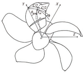
The three-dimensional coordinate conversion of the Kappel propeller is shown as follows (Wu, 2008):
$$ \begin{aligned} X= & X_m+C[S-0.5] \sin \phi \cdot \cos \varphi-f \cos \phi \cdot \cos \varphi \mp \\ & 0.5 t \cos \phi \cdot \cos \varphi \end{aligned} $$ (1) $$ \theta=\theta_m+C[S-0.5] \frac{\cos \phi}{r}+f \frac{\sin \phi}{r} $$ (2) $$ \begin{aligned} Y= & r \cos \theta+C[S-0.5] \sin \phi \cdot \sin \varphi-f \cos \phi \cdot \sin \varphi \pm \\ & 0.5 t \cos \phi \sin \varphi \end{aligned} $$ (3) $$ Z=r \sin \theta \pm 0.5 t \sin \phi $$ (4) where X, Y, and Z are the coordinate values of the point on the blade (Figure 1); C is the chord length; S is the dimensionless length distribution of the two-dimensional airfoil; Ф represents the pitch angle; f represents the camber; θm is the skew parameter; Xm is the rake parameter; t is the thickness; r is the radius of the cylindrical surface; φ is the included angle between the tangent of the rake distribution curve and the longitudinal coordinate axis.
2.2 Basic theory of propeller
If the diameter of the propeller is D, the rotation speed is n, the inlet velocity is VA, the water density is ρ, the thrust is T, and the torque is Q, then the advance speed coefficient (J), the thrust coefficient (KT), the torque coefficient (KQ), and the open-water propulsion efficiency (ηo) can be expressed as follows (Kerwin, 2010):
$$ K_T=\frac{T}{\rho n^2 D^4}=f_1\left(\frac{V_A}{n D}, \frac{n D^2}{v}, \frac{n^2 D^2}{g D}\right) $$ (5) $$ K_Q=\frac{Q}{\rho n^2 D^5}=f_2\left(\frac{V_A}{n D}, \frac{n D^2}{v}, \frac{n^2 D^2}{g D}\right) $$ (6) $$ \eta_o=\frac{K_T}{K_Q} \cdot \frac{J}{2 \pi}=f_3\left(\frac{V_A}{n D}, \frac{n D^2}{v}, \frac{n^2 D^2}{g D}\right) $$ (7) where $ V_A / n D$ is equal to J, which represents the motion similarity. nD2/ν is the Reynolds number, representing the viscous force similarity. n2D2/gD is the square of the Froude number, which represents gravity similarity.
To make the open performance of the propeller at the model scale parallel to that at the real scale, the following conditions are bound to be met.
$$ \frac{D_s}{D_m}=\lambda $$ (8) $$ \frac{V_{A m}}{n_m D_m}=\frac{V_{A s}}{n_s D_s} $$ (9) $$ \frac{V_{A m}}{V_{A s}}=\frac{1}{\lambda} \cdot \frac{n_m}{n_s} $$ (10) $$ \frac{n_m D_m^2}{v_m}=\frac{n_s D_s^2}{v_s} $$ (11) where λ is the scale ratio, the subscript s represents the real scale, and the subscript m represents the model scale.
2.3 Turbulence model
The RANS-based SST k-ω model proposed by Menter was adopted in this paper. The governing equation is shown as follows (Menter, 1994):
$$ \frac{\partial k}{\partial t}+U_j \frac{\partial k}{\partial x_j}=P_k-\beta^* k \omega+\frac{\partial}{\partial x_j}\left[\left(v+\sigma_k v_T\right) \frac{\partial k}{\partial x_j}\right] $$ (12) $$ \begin{aligned} \frac{\partial \omega}{\partial t}+U_j \frac{\partial \omega}{\partial x_j}= & \alpha S^2-\beta \omega^2+\frac{\partial}{\partial x_j}\left[\left(v+\sigma_\omega v_T\right) \frac{\partial \omega}{\partial x_j}\right] \\ & +2\left(1-F_1\right) \sigma_{\omega 2} \frac{1}{\omega} \frac{\partial k}{\partial x_i} \frac{\partial \omega}{\partial x_i} \end{aligned} $$ (13) where k is the turbulent kinetic energy; ω is the dissipation rate of specific turbulent energy; ν is the fluid kinematic viscosity coefficient; νT is the turbulent kinematic viscosity, and τij is the viscous shear stress.
2.4 Transition model
A transition phenomenon was observed from the laminar flow to the turbulence flow on the blade surface at the model scale when the Reynolds number is low to a certain extent. In ensuring the accuracy of the simulation, the transition must be considered at the model scale but not at the real scale (Hasuike et al., 2017). Considering the computational resources, the γ transition model was selected in this paper. The intermittent transmission equation is set as follows:
$$ \frac{\partial(\rho \gamma)}{\partial t}+\frac{\partial\left(\rho U_j \gamma\right)}{\partial x_j}=P_\gamma-E_\gamma+\frac{\partial}{\partial x_j}\left[\left(\mu+\frac{\mu_t}{\sigma_\gamma}\right) \frac{\partial \gamma}{\partial x_j}\right] $$ (14) $$ P_\gamma=F_{\text {length }} \rho S \gamma(1-\gamma) F_{\text {onset }} $$ (15) where S is the absolute value of the strain rate; μt is the turbulent vortex viscosity; Pγ is the production item; Eγ is the dissipation term; Fonset governs the location of transition, and Flenghth governs the length of the transition region.
3 Verification of the simulation method of TRP
Kappel propeller has few published test data, making the open-water performance test data of TRP P1727 issued by Hamburg Ship Model Basin (HSVA) (Klose et al., 2017) a good option for the validation of the CFD simulation method, which is related to the base size of mesh and turbulence model suitable for Kappel propeller.
3.1 Main scale parameters of P1727 TRP
The diameter of the propeller P1727 at the model scale is 238.6 mm, and that at the real scale is 7500 mm with a scale ratio of 31.428 compared with the model scale propeller. The main scale parameters of propeller P1727 are shown in Table 1.
Table 1 Main scale parameters of propeller P1727Propeller P1727 Scale ratio Diameter
(mm)Hub diameter ratio Model scale 1 238.6 0.154 2 Real scale 31.428 7 500 0.154 2 3.2 Setting of the calculation domain and mesh strategy
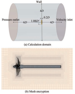
In this paper, the calculation domain was uniformly set as a cylinder (Figure 2(a)), which is divided into two parts, namely, the static region and the rotating region. The propeller diameter is set as D. The diameter of the static region is 4D, and the height is 10D. The diameter of the rotating region is 1.08D, and the height is 0.2D. The velocity inlet of the static region is 4D away from the propeller disk, and the pressure outlet is 6D downstream. During meshing, a tubular wake encryption area was added behind the propeller pressure surface to capture the velocity distribution of the wake field (Figure 2(b)).
3.3 Grid independence and turbulence model verification of propeller P1727 at the model scale
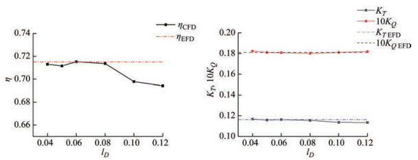
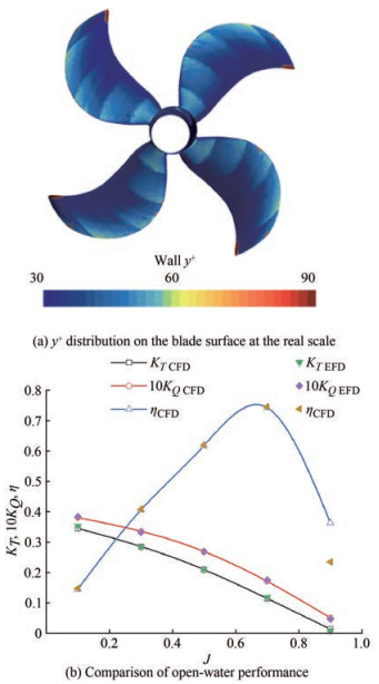
Here, the influence of the basic mesh size on the simulation results at the model scale was explored. The base size was set as lD. Six cases with base sizes of 0.004D, 0.005D, 0.006D, 0.008D, 0.01D and 0.012D under the same mesh strategy were calculated. The rotation speed is set as 12 r/s, and the advance coefficient J is set as 0.7. Turbulence model SST k-ω considering γ transition was also adopted in this study. As shown in Figure 3, the simulation results are stable when the base size is less than or equal to 0.008D, which is consistent with the test data. Considering the accuracy and time cost of simulation, this paper uniformly determined the base mesh size of 0.008D in the following study.
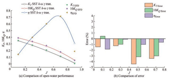
The simulation results of the SST k- ω turbulence model considering γ transition are consistent with the experimental values, in which the propulsion efficiency was calculated on the basis of the values of thrust coefficient and torque coefficient (Figure 4). The simulation error is less than 5%, of which the error of efficiency is smaller, and the error of thrust coefficient is greater.
3.4 Verification of the simulation method for propeller P1727 at the real scale
Then, this paper verified the accuracy of the open-water performance simulation of a real scale propeller. When the rotation speed is 2.14 r/s and the advance speed coefficient J is 0.7, the flow on the blade at the real scale has been in a turbulent state, thereby ignoring the transition phenomenon. The turbulence model SST k- ω was applied. The value range of y+ at the real scale is 30–90, with an average of 45, establishing a suitable thickness of the boundary layer. The total number of mesh cells is 6 million. The results of CFD simulation are consistent with the simulation data shown in Cheng et al. (2010), as shown in Figure 5(b).
4 Scale effect analysis of Kappel propellers with different end plates
Three Kappel propellers with different end plates were constructed, among which are two propellers, namely, propeller Kap02 and Kap04, with different bending degrees of the end plate and propeller Kap00 without an end plate. The open-water performance variation at four scales of 0.025, 1, 4, and 8 m was studied. The influence of the bending degree of the end plate on the scale effect, as well as the influence of the scale effect on the open-water performance, wake distribution, and pressure distribution of the Kappel propeller with different end plates at different scales, were explored.
4.1 Geometric model of Kappel propeller with different bending degrees
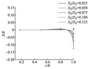
The distribution of other parameters, such as chord length, skew, and pitch, was not changed when the rake parameter varied. In quantifying the shape change of the end plate, the ratio of the curve length of the radial rake distribution line to the propeller radius was introduced (Eq. (16)). Figure 6 shows the rake distribution design of Kappel propellers, including Kap01, Kap02, Kap03, Kap04, and Kap05, with XS/DE values of 0.025, 0.05, 0.075, 0.1, and 0.125, respectively, by 4-order cubic Bspline scheme (Kim et al., 2007). XS represents the rake at the designated radius, namely at blade tip, and DE means propeller diameter.
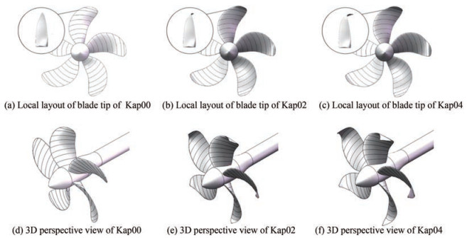
$$ S / R=\frac{L_{X_S / D_E}}{R} $$ (16) The three-dimensional model of three Kappel propellers, including Kap00, Kap02, and Kap04, is shown in Figure 7. The three-dimensional model of the propeller at different scales was obtained by scaling up the model propeller to 0.25 m. The corresponding relationship between the bending degree of the end plate and the series number, together with the corresponding parameters, is shown in Table 2.
Table 2 Series number and corresponding parameters of Kappel propellers with different end platesSeries number XS/DE S/R Immersion area ratio Kap00 0 1 1 Kap02 0.05 1.059 1.020 2 Kap04 0.1 1.143 1.058 3 4.2 Setting of working conditions
In this paper, the similarity of Froude number was applied to constrain the propeller speed. Therefore, three conditions of geometric similarity, kinematic similarity, and Froude similarity were satisfied when designing different scale working conditions (Table 3).
Table 3 Working conditions and Reynolds number of Kappel propeller at different scalesDiameter
(m)Rotation speed (r/s) Time step
(10−3 s)J VA
(m/s)Re 0.25 12 0.2 0.7 2.1 4.665 × 10⁵ 0.8 2.4 4.723 × 10⁵ 0.9 2.7 4.787 × 10⁵ 1 6 0.45 0.7 4.2 3.732 × 10⁶ 0.8 4.8 3.778 × 10⁶ 0.9 5.4 3.830 × 10⁶ 4 3 0.9 0.7 8.4 2.986 × 10⁷ 0.8 9.6 3.023 × 10⁷ 0.9 10.8 3.064 × 10⁷ 8 2.1 1.3 0.7 11.9 8.455 × 10⁷ 0.8 13.6 8.549 × 10⁷ 0.9 15.3 8.666 × 10⁷ 4.3 Scale effect of the open-water performance
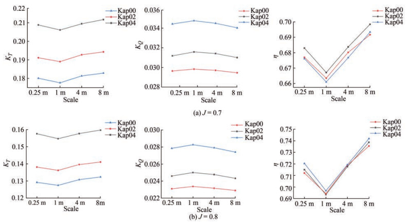
The open-water performance of Kap00, Kap02, and Kap04 propellers at different scales was obtained. When the advance coefficients are 0.7 and 0.8, the thrust coefficient, torque coefficient, and propulsion efficiency vary with the propeller scale (Figure 8).
As shown in Figure 8, the thrust coefficient and torque coefficient of the propellers with different end plates have the same variation trend with the scale. When the scale increases from 0.25 to 1 m, the thrust coefficient and efficiency of all propellers decrease, whereas the torque coefficient increases gradually because of the flow state change from laminar flow to turbulence. Based on the document (Hasuike et al., 2017), the thrust output could be broken down by the magnification of the flow separation and boundary layer of the turbulence flow with increasing Reynolds number in the range of 4.5×10⁵−2.5× 10⁶, which is within the Reynolds number range when the scale is between 0.25 and 1 m (Table 3). As shown in Table 3, the propeller Reynolds number at a 0.25 m scale is 4.8×10⁵, which is in the laminar-turbulence conversion region. When the scale is 1 m, the Reynolds number is 3.77×10⁶, which is completely in a turbulent state. Compared with previous studies (Streckwall et al., 2013), the friction resistance coefficient curve is near the peak at this condition.
When the scale is larger than 1 m, the surface flow is completely turbulent, and the change trend of propeller performance with scale is the same as the empirical formula in ITTC1978. As the scale rises, the thrust coefficient and propulsion efficiency of the propellers increase, whereas the torque coefficient decreases. Compared with the model scale (scale of 0.25 m) calculation results with regard to the same propeller type with scales of 1, 4, and 8 m, the change amplitude of the thrust coefficient, torque coefficient, and efficiency of Kappel propellers, which can be expressed as ΔKT, ΔKQ, and ΔKη, respectively, is shown in Figures 9–11. The calculation formula of the thrust coefficient, torque coefficient, and efficiency change amplitude in Figures 9–11 is shown in Eqs. (17)–(19).
$$ \Delta K_T=\frac{K_{T s}-K_{T m}}{K_{T m}} $$ (17) $$ \Delta K_Q=\frac{K_{Q s}-K_{Q m}}{K_{Q m}} $$ (18) $$ \Delta \eta=\frac{\eta_s-\eta_m}{\eta_m} $$ (19) As shown in Figure 9, the changes in thrust coefficient and propulsion efficiency are inconsistent. However, the torque coefficient shares the same rule at each advance speed, and the change in the amplitude of Kappel propellers with end plates is greater than that of propeller Kap00, of which propeller Kap02 shows the largest variation.
As shown in Figure 10 and Figure 11, when J is equal to 0.7 or 0.8, the change rate of the thrust coefficient decreases with the increase of the bending degree of the end plate, whereas the change amplitude with different end plates is not evident. With regard to the torque coefficient, the change range of the Kappel propeller with an end plate is significantly greater than that of the propeller without an end plate. The change rate of the torque coefficient accelerates with the increase of the bending degree of the end plate. With regard to efficiency, no evident rule and no significant difference in the variation range of the three propellers were observed when J is equal to 0.7 or 0.8.
The overall rule of the Kappel propeller's scale effect is consistent with that of the conventional propeller. The thrust coefficient and propulsion efficiency of the Kappel propeller increase with the increase of the scale, whereas the torque coefficient decreases at a scale range between 1 and 8 m. The torque coefficient of the Kappel propeller, except for the thrust coefficient and propulsion efficiency, increases with the change of scale, whereas that of an ordinary propeller increases with the bending degree of the end plate.
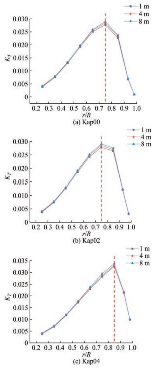
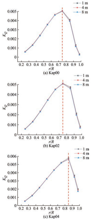
When J = 0.8, the radial distributions of the thrust coefficient and torque coefficient of propellers with different scales and different end plates are shown in Figure 12 and Figure 13.
By comparing the radial distribution of the thrust coefficient and torque coefficient under different scales of the same model, the thrust coefficient within each radius range of the Kappel propeller increases with the increase of the scale, whereas the torque coefficient decreases with the scale. The magnitude of the thrust coefficient, which changes with the scale in different radius ranges, is not consistent. The point where the thrust coefficient changes most violently is found at the region of the maximum radial thrust distribution, and the locations for different Kappel propellers are different. In general, with the increase of the bending degree of the end plate, the position where the maximum thrust coefficient occurs moves along the radius toward the bending point of the end plate.
The torque coefficient of the Kappel propeller varies with the scale, which is distinguished from that of the thrust coefficient. The point where the torque coefficient changes violently with the scale is found between the point of maximum torque and the blade tip, which is not symmetrically distributed on both sides as the thrust coefficient does. Moreover, with the intensification of end plate bending, the area where the torque coefficient changes significantly is closer to the blade tip. The scale does not influence the overall radial distribution of the thrust coefficient and torque coefficient, except for the distribution near the maximum value. In addition, the thrust coefficient changes evidently on both sides of the maximum value, whereas the torque coefficient changes evidently on the side near the blade tip and the point of the maximum value. As shown in Figure 13, the influence of the end plate on the scale effect of propeller torque distribution is reflected in the position r/R = 0.7, and the greater the bending degree, the greater the change of torque near the blade tip with scale.
4.4 Scale effect analysis of Kappel propeller flow field with different end plates
This paper analyzed the axial velocity of the flow field for three groups of propellers when J is 0.8. For comparison, the axial velocity is dimensionless, as shown in Eq. (20), where V0 is the advance speed, Vi is the velocity along the propeller axis, and U represents the dimensionless axial velocity.
$$ U=\frac{V_i}{V_0} $$ (20) 4.4.1 Wake field distribution analysis of Kappel propellers with different end plates
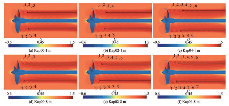
The wake fields of propellers Kap00, Kap02, and Kap04 at the scales of 1 and 8 m were obtained (Figure 14). As shown in the figure, the coverage area of the high-speed region (dark-red region) changes significantly. With the increase of scale, the high-speed area gradually extends to the front of the spiral, closer to the propeller blade, with its growing area. The increase in the high-speed area indicates that the kinetic energy of the wake increases with the increase of the scale, which is related to a strong propulsion ability based on the ideal propeller theory, which may not be verified clearly by the variation of the tip vortex contraction (Figure 15). This finding also reflects the law presented in Section 4.3; that is, the thrust coefficient of the propeller increases with the scale.
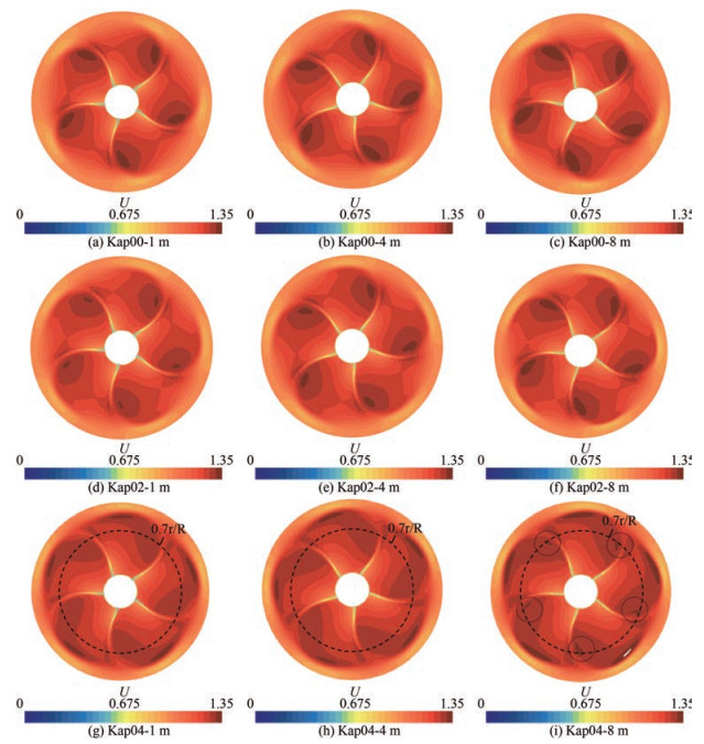
The axial velocity distribution 0.08D downstream the propeller disk was extracted (Figure 16). The form of axial velocity distribution for the three propellers does not change with the scale, but the high-speed area has evident variation. Comparing Figures 16(g)–16(f), the highspeed area of the Kap04 propeller has grown, and the reappearance of the high-speed region near 0.7r/R, which reflects the amplitude of wake velocity, slightly increases with the scale. Moreover, the wake high-speed zone of propeller Kap02, that is, originally dispersed, gradually merges into a circle with the increase of scale. Therefore, the fusion trend of the propeller wake will become evident on a larger scale.
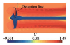
In exploring the velocity distribution in detail, a probe line was set at the first vortex of the propeller wake when J is equal to 0.8, of which the position can be converted considering the scale ratio shown in Figure 17, thereby obtaining the radial distribution of axial velocity values in Figure 18.
The change trend of the axial velocity on the three detection lines remains the same with the increase of the scale. The higher the Reynolds number, the greater the change of the axial velocity at the vortex, and the stronger the strength of the tail vortex. The dimensionless axial velocity distribution curves of the three propellers are quite different. The greater the bending degree of the end plate, the faster the change, and the sharper the display on the image.
4.4.2 Flow field distribution of Kappel propellers near the blade tips
The principal difference that distinguishes the Kappel propeller from the conventional propeller is the tip geometric structure, which is worthy of analysis on the flow field near the blade tip for Kappel propellers at unequal scales (Figure 19).
Figure 19 shows that the form of the flow field distribution in the lateral view generally remains invariable for the same type of Kappel propeller at the scales of 1 and 8 m. In the case of a 1 m scale, the low-speed or highpressure zone is found close to the tip in the pressure side for propeller Kap00, which induces disordered flow near the tip. By contrast, the flows near the tip of propellers Kap02 and Kap04 are steady and smooth. In the case of an 8 m scale, the flow across the tip starts to affect the field near the tip of propellers Kap00 and Kap02. With the increase of scale, the cross flow near the tip occurs for propeller Kap00, together with the reverse flow on the pressure side surface a little away from the tip for propeller Kap02, which is obstructed by the coming flow. On the contrary, the flow field remains stable without tip cross flow for propeller Kap04 at the scales of 1 and 8 m. The abovementioned phenomena indicated that the field near the Kappel propeller tip exhibits a cross flow trend with the increase of scale, which can be delayed by the end plate.
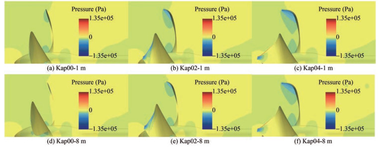
The pressure distribution of propellers Kap00, Kap02, and Kap04 at the scales of 1 and 8 m from a lateral view is presented in Figure 20, which might be helpful in analyzing the flow field near the tip (Figure 19) and the velocity distribution of the overall field (Figure 14). Therefore, the low-pressure zone in the suction side of different scales shares a consistent form, whereas the relative area tends to dwindle slightly as the scale rises, which increases with the enlargement of the bending degree of the end plate.
5 Conclusions
In this paper, a series of detailed scale effect studies have been conducted on Kappel TRP. The performance was simulated by CFD, and the scale effect of Kappel propellers with different bending degrees on the open-water performance and velocity field distribution were studied. The main conclusions are drawn as follows:
1) The scale effect of Kappel propellers with two types of different end plate bending degrees and one type without bending at the scales of 0.25, 1, 4, and 8 m was simulated (Reynolds number: 4.665×10⁵−8.666×10⁷). Therefore, the scale effect of the torque coefficient is greater than that of the conventional propeller. The greater the bending degree of the end plate, the greater the scale effect of the torque coefficient. However, no evident difference is observed between the scale effect of thrust coefficient and efficiency. It should be noted that, due to the fluid state transition from laminar flow to turbulence flow, the thrust coeffecient and propulsion efficiency cut down abruptly for the scale of 1 m compared with the other cases.
2) The influence of the scale effect of Kappel propellers with different end plates on the velocity distribution was analyzed. With the rise of the scale, the high-speed area of dimensionless axial velocity of the propeller wake grows, and the trend of propeller wake fusion accelerates. The variation of dimensionless axial velocity at the first vortex of the propeller wake at different scales shows that the increasing scale will lead to the enhancement of the wake strength. In addition, the cross flow tends to show its presence near the blade tip when the scale increases, which could be delayed by the end plate structure of the blade.
Competing interest The authors have no competing interests to declare that are relevant to the content of this article.Open Access This article is licensed under a Creative Commons Attribution 4.0 International License, which permits use, sharing, adaptation, distribution and reproduction in any medium or format, as long as you give appropriate credit to the original author(s) and the source, provide a link to the Creative Commons licence, and indicate if changes were made. The images or other third party material in this article are included in the article's Creative Commons licence, unless indicated otherwise in a credit line to the material. If material is not included in the article's Creative Commons licence and your intended use is not permitted by statutory regulation or exceeds the permitted use, you will need to obtain permission directly from the copyright holder. To view a copy of this licence, visit http://creativecommons.org/licenses/by/4.0/. -
Table 1 Main scale parameters of propeller P1727
Propeller P1727 Scale ratio Diameter
(mm)Hub diameter ratio Model scale 1 238.6 0.154 2 Real scale 31.428 7 500 0.154 2 Table 2 Series number and corresponding parameters of Kappel propellers with different end plates
Series number XS/DE S/R Immersion area ratio Kap00 0 1 1 Kap02 0.05 1.059 1.020 2 Kap04 0.1 1.143 1.058 3 Table 3 Working conditions and Reynolds number of Kappel propeller at different scales
Diameter
(m)Rotation speed (r/s) Time step
(10−3 s)J VA
(m/s)Re 0.25 12 0.2 0.7 2.1 4.665 × 10⁵ 0.8 2.4 4.723 × 10⁵ 0.9 2.7 4.787 × 10⁵ 1 6 0.45 0.7 4.2 3.732 × 10⁶ 0.8 4.8 3.778 × 10⁶ 0.9 5.4 3.830 × 10⁶ 4 3 0.9 0.7 8.4 2.986 × 10⁷ 0.8 9.6 3.023 × 10⁷ 0.9 10.8 3.064 × 10⁷ 8 2.1 1.3 0.7 11.9 8.455 × 10⁷ 0.8 13.6 8.549 × 10⁷ 0.9 15.3 8.666 × 10⁷ -
Abdel-Maksoud M, Heinke HJ (2003) Scale effects on ducted propellers. Twenty-Fourth Symposium on Naval Hydrodynamics, Washington DC, 744–759 Bhattacharyya A, Krasilnikov V, Steen S (2016a) A CFD-based scaling approach for ducted propellers. Ocean Engineering 123: 116–130. https://doi.org/10.1016/j.oceaneng.2016.06.011 Bhattacharyya A, Krasilnikov V, Steen S (2016b) Scale effects on open water characteristics of a controllable pitch propeller working within different duct designs. Ocean Engineering 112: 226–242. https://doi.org/10.10166/j.oceaneng.2015.12.024 Bhattacharyya A, Krasilnikov V, Steen S (2015) Scale effects on a 4-bladed propeller operating in ducts of different design in open water. Fourth International Symposium on Marine Propulsors, Austin, 604–611 Chen X, Huang Y, Wei P, Zhang Z, Jin F (2018) Numerical analysis of scale effect on propeller E1619. 37th International Conference on Ocean, Offshore and Arctic Engineering, Madrid, 243–252 Cheng H, Chien Y, Hsin C, Chang K, Chen P (2010) A numerical comparison of end-plate effect propellers and conventional propellers. Journal of Hydrodynamics 22(5): 495–500. https://doi.org/10.1016/S1001-6058(09)60242-0 Choi J, Park H, Kim H (2014) A numerical study of scale effects on performance of a tractor type podded propeller. International Journal of Naval Architecture and Ocean Engineering 6(2): 380–391. https://doi.org/10.2478/IJNAOE-2013-0186 Dong X, Li W, Yang C, Yang C, Francis N (2018) RANSE-based simulation and snalysis of scale effects on open-water performance of the PPTC-Ⅱ benchmark propeller. Journal of Ocean Engineering and Science 3(3): 186–204. https://doi.org/10.1016/j.joes.2018.05.001 Hasuike N, Okazaki M, Okazaki A, Fujiyama K (2017) Sacle effects of marine propellers in POT and self propulsion test conditions. Fifth International Symposium on Marine Propulsors, Espoo, 356–363 Helma S, Streckwall H, Richter J (2018) The effect of propeller scaling methodology on the performance prediction. Journal of Marine Science and Engineering 6(2): 60. https://doi.org/10.3390/jmse6020060 Helma S (2016) A scaling procedure for modern propeller designs. Ocean Engineering 120: 165–174. https://doi.org/10.1016/j.oceaneng.2015.10.009 Helma S (2015) An extrapolation method suitable for scaling of propellers of any design. Fourth International Symposium on Marine Propulsors, Austin, 452–465 Kerwin JE, Hadler JB (2010) The principles of naval architecture series. The Society of Naval Architects and Marine Engineers, Jersey City, 67–100 Kim GD, Lee CS, Kerwin JE (2007) A B-spline based higher order panel method for analysis of steady flow around marine propellers. Ocean Engineering 34(14–15): 2045–2060. https://doi.org/10.1016/j.oceaneng.2007.02.013 Klose R, Schulze R, Hellwig-Rieck K (2017) Investigation of prediction methods for tip rake propellers. Fifth International Symposium on Marine Propulsors, Espoo, 688–696 Krasilnikov V, Sun J, Halse K (2009) CFD investigation in scale effect on propellers with different magnitude of skew in turbulent flow. First International Symposium on Marine Propulsors, Trondheim, 25–35 Kuiper G (1992) The Wageningen propeller series. MARIN, Wageningen, The Netherlands, 10–79 Liu L, Chen M, Wu Y, Zhang Z, Wang X (2021) Numerical study on the scale effect of high-skew propeller E1619. International Joint Conference on Civil and Marine Engineering (JCCME), Hongkong, 365–376 Lungu A (2019) Scale effects on a tip rake propeller working in open water. Journal of Marine Science and Engineering 7(11): 404. https://doi.org/10.3390/jmse7110404 Menter FR (1994) Two-equation eddy-viscosity turbulence models for engineering applications. AIAA Journal 32(8): 1589–1605. https://doi.org/10.2514/3.12149 Peravali SK, Bensow RE, Gyllenram W, Shiri AA (2016) An investigation on ITTC78 scaling method for unconventional propellers. 12th International Conference on Hydrodynamics, Delft, 441–448 Praefke E (1994) Multi-component propulsors for merchant ships-design considerations and model test results. SNAME 7th Propeller and Shafting Symposium, Virginia Beach, USA, 179–186 Sánchez-Caja A, González-Adalid J, Pérez-Sobrino M, Sipilä T (2014) Scale effects on tip loaded propeller performance using a RANSE Solver. Ocean Engineering 88: 607–617. https://doi.org/10.1016/j.oceaneng.2014.04.029 Streckwall H, Greitsch L, Scharf M (2013) An advanced scaling procedure for marine propellers. Third International Symposium on Marine Propulsors, Launceston, 136–142 Sun S, Hu Z, Wang C, Guo Z, Li X (2021) Numerical prediction of scale effect on propeller bearing force of a four-screw ship. Ocean Engineering 229: 108974. https://doi.org/10.1016/joceaneng.2021.108974 Sun S, Wang C, Guo C, Zhang Y, Sun C, Liu P (2020) Numerical study of scale effect on the wake dynamics of a propeller. Ocean Engineering 196: 106810. https://doi.org/10.1016/j.oceaneng.2019.106810 Sun C, Wang C, Sun S, Chang X, Zhang L (2018) Numerical prediction analysis of the fluctuating pressure and rudder force of full-scale hull-propeller-rudder system. Ocean Engineering 147: 580–590. https://doi.org/10.10166/j.oceaneng.2017.11.006 Ueno M, Suzuki R, Tsukada Y (2019) Full-scale ship propeller torque in wind and waves estimated by free-running model test. Ocean Engineering 184: 332–343. https://doi.org/10.1016/j.oceaneng.2019.04.057 Wu J (2008) Design and spatial geometric representation of Kappel propeller. Master thesis, Taiwan Ocean University, Jilong Yao H, Zhang H (2018) Numerical simulation of boundary-layer transition flow of a model propeller and the full-scale propeller for studying scale effects. Journal of Marine Science and Technology 23: 1004–1018. https://doi.org/10.1007/s00773-018-0528-4
| Citation: | Chen-Wei Chen, Xupeng Chen, Zhaoye Zhou, Liwan Chen (2023). Scale Effect of a Kappel Tip-Rake Propeller. Journal of Marine Science and Application, 22(3): 421-434. https://doi.org/10.1007/s11804-023-00359-1 |

