Multipath Geometry Channel Model in Shallow Water Acoustic Communication
https://doi.org/10.1007/s11804-023-00339-5
-
Abstract
Using the underwater acoustic channel (UWA) for information dissemination requires a high data rate. However, some phenomena like refraction, reflection, phase shift, and high attenuation are undesirably apparent when the subject of using UWA is raised. Accordingly, sound communication would be a highly challenging task to be accomplished. Therefore, proposing a model of acoustic underwater communication channels is critical because of the multipath interference originating from the surface and bottom of the ocean. In this contribution, a straightforward geometry channel model for vertical and horizontal marine communications is presented. To do so, transmission loss and channel impulse response are analyzed as a function of transmitter and receiver distance, water depth, and reflection rate. The results of the model proposed in this paper are in very good agreement with those available in the literature. Initial findings indicate that the delay spread of horizontal communication with a 1 000 m range reaches79 ms and 0.3 s for 30 m vertical communication.Article Highlights• A multipath geometry channel model is described as a direct path and multipath reflections from the surface and bottom.• A straightforward geometry channel model was designed and simulated that can be applied to vertical and horizontal communication.• The performance of the channel model with different parameters was evaluated and test, showing good agreement compared with other works. -
1 Introduction
Underwater wireless communication has become a highly competitive topic due to the growing number of civil and military applications of ocean monitoring and information transmission. Underwater acoustic channels are challenging to communicate because of their features like strong multipath propagation, Doppler shifts, and high attenuation (Stojanovic and Preisig, 2009; Abdelkareem, et al., 2011).These variables can have an impact on the effectiveness and capacity of communication channels because they produce frequency-selective fading in the frequency response of the channel. This fading originates from the time propagation of the transmitted signal caused by multipath propagation. The high frequencies are quickly absorbed over large distances underwater, and the underwater channel cannot use them. The acoustic signals are the best candidate for underwater communication, because they can operate at a distance of several kilometers. Moreover, they take advantage of having frequency ranging from tens of hertz to 1 MHz (John Heidemann, et al., 2012). Modeling underwater acoustic channels provides an effective method for channel analysis by considering the effect of fundamental underwater environment parameters on acoustic channels.
A signal traveling from a source to a receiver does not always take the shortest path. However, it generally suffers from bottom and surface reflections and also refraction due to the differences in sound speed (Hui and Sheng, 2022). Inter-symbol interference (ISI) is a phenomenon whereby several replicas arrive at a recipient at different times, resulting in distortion of the transmitted signals in shallow water conditions (Coates, 1994; Elamassie, et al., 2018). Therefore, efficient solutions for underwater acoustic communications necessitate multipath analysis, which requires accurate channel modeling of the underwater communication system.
Researchers have recently focused on multipath propagation analysis models in underwater environments. Widiarti et al. (2018) analyzed the heights of the transmitter and receiver at various distances to offer a simple, effective multipath geometry-based channel model for time-reversal communication. They indicated that multipath analysis is a fundamental matter in underwater acoustic horizontal channel communication. Zhou et al. (2019) developed a geometry-based model to simulate multipath scattering scenarios between the transmitter and the receiver that communicate horizontally. The effect of scattering environments on propagation characteristics was explored with little complexity using a rectangle to describe the communication environments of the ocean's vertical cross-section. The angle of arrival distribution for the propagation multipath model in a UW channel with incoherent scattering from the surface and the bottom was estimated in (Rawat, et al., 2020) where the transmitter and receiver positioned on horizontal line. Incoherent scattering has been added to the dispersed field with high-frequency acoustic waves or rough boundaries. Such a representation could help create efficient and accurate high-frequency communication systems between mobile UW and surface platforms. A channel model for non-stationary wideband UWA was proposed in (Zhu, et al., 2021). This geometry-based stochastic model incorporated multiple motion effects between the transmitter and receiver in a horizontal communication, time-varying angles, distances, cluster locations with channel geometry, and ultra-wideband property, making it more realistic and capable of supporting extended time/distance simulations. Based on previous literatures, most channel models provide the description to the multipath propagation in an environment where the transmitter and receiver communicate horizontally.
In the light of delayed receiver copies creating interference intersymbol, the propagation delay of multipath compared to the direct path is a crucial characteristic in the underwater channel that influences system performance.
The contribution of this paper, a geometric channel model is proposed to represent multipath propagation based on a triangle to describe the characteristics of shallow water acoustic for vertical and horizontal communication where the current models and simulators describe only the horizontal communication. The proposed model combines direct and reflected paths, and it is expected to be randomly dispersed over the ocean's floor and surface. In fact, this study analyzes the effect of multipath propagation on channel's impulse response and transmission loss for vertical and horizontal communications by using mathematical formulas. The formulations are for spreading loss as a function of distance and for absorption loss as a function of frequency to determine transmission loss at each link and provide a measurement of the received signal strength. Due to variations in the lengths of the original signal paths and the delay spread, signals traveling by multipath propagation arrive at the receiver with varying arrival times and amplitudes.
This paper is organized as follows: In Section 2, the channel characteristics theory employed in communications at UWA is presented. In Section 3, a new channel model for geometry is depicted. A comparison of the suggested model with the results of the Bellhop simulator is made in Section 4. Eventually, findings and discussion are presented in Section 6.
2 UWA communication channel characteristics
The primary characteristics of a channel model, including propagation delay, absorption and spreading loss, and transmission loss, must be understood before introducing the proposed model. Because the underwater channel suffers from time-varying multipath and low sound speed, a scattering delay of more than 100 symbols occurs and causes intersymbol interference (ISI) (Abdelkareem, et al., 2016). The channel model assumes that the wave propagation is a combination of the multipath and direct path reflections, as demonstrated in Figure 1. Due to bandwidth limitations, the signal sensitivity of a multipath propagation environment changes with time and is heavily influenced by transmitter and receiver position. The initial reflection of the ocean's surface is shown by the green path, whereas the red path represents the initial reflection at the bottom of ocean. The vertical and horizontal connection settings are critical in determining the rate of multipath propagation (Lou and Ahmed, 2022).
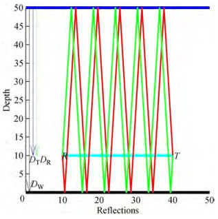 Figure 1 Multipath layout reflections in the communication channel
The intensity decay with increasing range is described by transmission loss (TL), which is measured in decibels. The value of TL is calculated using total spreading and attenuation loss (Coates, 1991):
$$ \mathrm{TL}(f)=2 {\rm{ \mathsf{ α} }}_z+k \log _{10}(r)+a(f) r, $$ (1) where r is the propagation range in meters that describe the propagation length of both direct path and multipath. Because the transmitter and receiver are both toroidal beam-shaped transducers, the attenuation αz in the zy and zx planes is fixed at 15 dB, k is the spreading factor chosen to account for the spreading loss. The second term of Eq. (1) determines the spreading loss through spherical or cylindrical spreading. Because attenuation rises with frequency for every unit distance, this influence may be severe in shallow water at very high frequencies. The fundamental loss rule for spherical spreading with k = 20 is the "inverse-square law, " which characterizes the intensity I (r) at a distancer with respect to the intensity at a range of 1 m used as a reference. Cylindrical spreading law, with k = 10, may apply instead of spherical propagation circumstances when the water acts as an acoustic waveguide owing to reflections between the sea surface and bottom. Due to the fact that low-frequency sound is especially well-penetrated through the seabed, and also boundary reflections are highly dependent on both the sea state and the bottom material characteristics, the cylindrical rule attempts to under-estimate loss. In computations, a "practical" law is selected as an intermediate when k = 15 is between the spherical and cylindrical norms. The third term of Eq. (1) represents attenuation in the water, which is mostly produced by viscous friction at frequencies over 1 MHz. When the signal's frequency lowers, the attenuation value for saltwater is lower than the value for pure water because of a combination of molecular resonance phenomena. The presence of magnesium sulfate in saltwater solution begins to affect an additional attenuation above the distill water loss at frequencies lower than 500 kHz, ultimately elevating the attenuation effectively by a factor of roughly 18 for frequencies lower than 70 kHz. Despite its low quantity in the ocean, boric acid causes a consistent 16-fold increase in the reduction at frequencies lower than 700 Hz.
The next equations are related to calculating α(f):
$$ {\rm{ \mathsf{ α} }}(f)={\rm{ \mathsf{ α} }}_1+{\rm{ \mathsf{ α} }}_2+{\rm{ \mathsf{ α} }}_3 $$ (2) where,
$$ {\rm{ \mathsf{ α} }}_1=a f^2, \quad \text { (Freshwater attenuation) } $$ (3) $$ {\rm{ \mathsf{ α} }}_2=b f_0 /\left(1+\left(f_0 / f\right)^2\right), \quad\left(\mathrm{MgSO}_4 \text { Relaxation }\right) $$ (4) $$ {\rm{ \mathsf{ α} }}_3=c f_1 /\left(1+\left(f_1 / f\right)^2\right), \text { (Boric acid relaxation) } $$ (5) $$ \begin{aligned} a= & 1.3 \times\left(10^* \exp (-7)\right)+2.1 \times \\ & \left(\left(10^* \exp (-10)\right)(\mathrm{T}-38)^2\right. \end{aligned} $$ (6) $$ \rm{b}=2 \mathit{S} \times\left(10^* \exp (-5)\right) $$ (7) $$ c=1.2 \times 10^{-4} $$ (8) $$ f_0=50 \times(T+1) $$ (9) $$ f_1=(10)^{(T-4) / 100} $$ (10) The salinity is denoted by S in h, the temperature by T in Celsius, and the frequency by f in kHz.
3 Proposed geometry channel model
As mentioned in Eq. (1), for computingr we need first to determine the propagation delay for direct and multipath and multiply by speed sound, so it is essential to model a channel that describes the direct and multipath propagation delay to compute the transmission loss for each path. The suggested propagation geometry model employs a triangle to represent the multipath propagation in shallow water communication channels, supposing that multipath reflection happens randomly at the surface and bottom of the ocean. Direct path propagation delay TD is determinedaccording to the velocity formulation expressed as:
$$ T_D=L / c $$ (11) where L is the distance between the transmitter and receiver as a direct path and c represents the sound speed. According to the proposed model, the value of receiver depth DR varies with respect to transmitter depth DT and the separation distance L between the transmitter and receiver. As indicated in Figure 2a, DR is computed depending on the angle between the water column and the transceiver's vertical line, where θ=0° represents the vertical connection as shown in Figure 2b and θ=90° for the horizontal connection, as indicated in Figure 2c. When θ=0, the depth of DR is computed based on DT and L as indicated in Eq. (12) while when θ =90°, the depth of DR is computed based on DT.
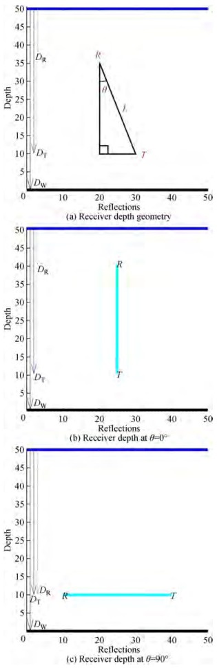 Figure 2 Locating the depth of the receiver
$$ D_R=D_T-L^* \cos (\theta) $$ (12) Figure 3 shows that whether the signal is moving in a straight line or a multipath, the propagation delay may be determined by using the Pythagorean theorem of right triangles. The hypotenuse duration represents the required time for one reflection to travel from a transmitter through the medium toward a receiver. Assumed reverberations may be divided into two categories: surface reflections, in which the first reflection takes place on the surface, and bottom reflections, in which the initial reflection takes place on the seabed.
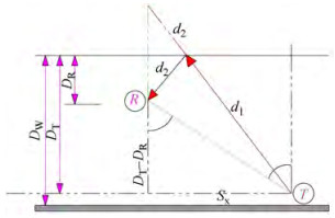 Figure 3 Multipath surface reflection using the Pythagorean theorem
3.1 The propagation delay of surface reflections
Based on the Pythagorean theorem, S constitutes d1, the distance between the transmitter and the surface after the first reflection, and d2 is the distance from the surface to the receiver. After providing an extension to d1, Sx is the side next to the hypotenuse, and Sy is the side opposite the hypotenuse and can be given via the following relations:
$$ S=\sqrt{S_x^2+S_y^2} $$ (13) $$ S_y=D_T+D_R $$ (14) To calculate Sx, it is observed in Figure 4 by considering two transient vertical line segments from points T and R that are parallel to each other and intersected by a blue diagonal line, and the resulting angles will be equal in pairs (alternate angles) and θ = θ1. Also,
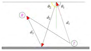 Figure 4 multipath propagation for N=2
$$ \theta_1+\theta_2=90 \Rightarrow \theta_1=90-\theta_2 $$ (15) $$ \cot \left(\theta_2\right)=\frac{S_x}{D_T-D_R}, $$ (16) $$ \because \theta=\theta_1, \Rightarrow \therefore \tan (\theta)=\frac{S_x}{D_T-D_R} $$ (17) $$ S_x=\left(D_T-D_R\right) \tan \theta $$ (18) For the number of reflections, N, the multipath propagation is represented as shown in Figure 4.
To represent the multipath propagation in this situation, Sx is unaffected by reflections while Sy changes, resulting in an extension of d1, d2 and d3.
It is assumed θ1 and θ2 are two consecutive reflection angles, the trigonometric angle d1 with θ1 and the trigonometric angle d2 with θ2, the following relations hold:
$$ \begin{aligned} \theta_2= & 180-\theta_1 \Rightarrow \sin \left(\theta_2\right)=\sin \left(\theta_1\right) \\ & \text { and } \cos \left(\theta_2\right)=\cos \left(\theta_1\right) \end{aligned} $$ (19) $$ \therefore \tan \left(\theta_2\right)=-\tan \left(\theta_1\right) \Rightarrow m\left(d_2\right)=-1^* m\left(d_1\right) $$ (20) where θ1 and θ2 are two arbitrary consecutive reflection angles. Therefore, it can be written that:
$$ \forall i \in \mathbb{N} m\left(d_{i+1}\right)=-1^* m\left(d_i\right), $$ (21) by taking absolute value for two sides:
$$ \forall i \in \mathbb{N}\left|m\left(d_i\right)\right|=\left|m\left(d_1\right)\right| $$ (22) Both consecutive reflection lines have the same slope as the opposite sign. According to the latter relation, all the reflection lines can place along the first reflection line allowing the creation of the vector S that moves horizontally and vertically, as shown in Figure 5.
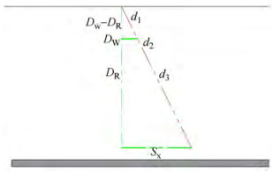 Figure 5 Equivalent model for multipath propagation when N=2
For every number of surface reflections, n, between 1 and N, the propagation delay is calculated as:
$$ S_{y_n}=D_T+\left\lfloor\frac{n}{2}\right\rfloor 2 D_W+(-1)^{n+1} D_R $$ (23) where DW is the water depth. To demonstrate that Eq. (23) is valid for all natural numbers approved by induction is used, the following procedure is adopted with figures, approve by induction assume first the equation is true when n=1 then it must be true when N=n+2. Again, approve by induction assume the equation is true when n=2 then it must be true when N=n+2:
Suppose n=1.
$$ S_{y_1}=D_T+\left\lfloor\frac{1}{2}\right\rfloor 2 D_W+\left((-1)^{1+1} D_R\right) \Rightarrow S_{y_1}=\left(D_T+D_R\right) $$ (23a) Suppose n is an odd natural number, so $n \in \mathbb{N}_O=\{1.3 .5 . \cdots\}$. Assume Syn is correct, to prove Syn + 2 will be also correct. Suppose n increases by two units.
Accordingly, two consecutive reflection vectors with opposite slopes are added to the previous set of reflections, the first reflection vector coming from the sea level to the depth of the sea and the second reflection vector going from the ocean's depth to the sea level. Each of these two moves by DW on the vertical axis. Hence, the total displacement increases by 2DW as shown in Figure 6.
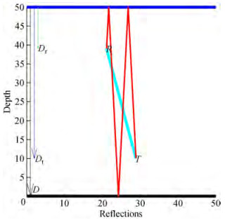 Figure 6 Surface reflections when N=n+2 with n=1
$$ S_{y_{n+2}}=S_{y_n}+2 D_W(N=3) $$ (23b) $$ S_{y_{n+2}}=D_T+\left\lfloor\frac{n}{2}\right\rfloor 2 D_W+(-1)^{n+1} D_R+2 D_W $$ (23c) $$ S_{y_{n+2}}=D_T+\left(\left\lfloor\frac{n}{2}\right\rfloor+1\right) 2 D_W+\left((-1)^{n+1} D_R\right) $$ (23d) $$ S_{y_{n+2}}=D_T+\left\lfloor\frac{n+2}{2}\right\rfloor 2 D_W+\left((-1)^{n+1} D_R\right) $$ (23e) ∴ Syn + 2 is correct by Eqn (22).
For natural odd number approving by induction is applied:
$$ \forall n \in \mathbb{N}_O ; S_{y_n}=D_T+\left\lfloor\frac{n}{2}\right\rfloor 2 D_W+\left((-1)^{n+1} D_R\right) $$ (23f) Suppose n=2 as shown in Figure 7, by Eq. (23)
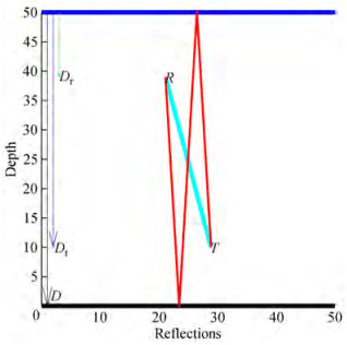 Figure 7 Surface reflections when N=2
$$ S_{y_2}=D_T+\left\lfloor\frac{2}{2}\right\rfloor 2 D_W+\left((-1)^{2+1} D_R\right) $$ (23g) $$ S_{y_2}=D_T+1^* 2 D_W+\left((-1)^3 D_R\right) $$ (23h) $$ S_{y_2}=D_T+1^* 2 D_W-D_R $$ (23i) Suppose n is an even natural number, so $n \in \mathbb{N}_E=\{2.4 .6 . \cdots\}$.
Assume Syn is correct, to prove Syn + 2 will be also correct. Suppose n increases by two units.
So two consecutive reflection vectors with opposite slopes are added to the previous set of reflections, the first reflection vector coming from the sea level to the depth of the sea and the second reflection vector going from the ocean's depth to the sea level.
Each of these two moves by DW on the vertical axis. So the total displacement increases by 2DW on the vertical axis, as shown in Figure 8.
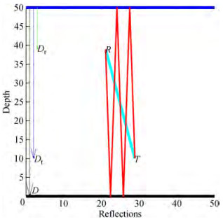 Figure 8 Surface reflections when N=n+2 with n=2
$$ S_{y_{n+2}}=S_{y_n}+2 D_W $$ (23j) $$ S_{y_{n+2}}=D_T+\left(\left\lfloor\frac{n}{2}\right\rfloor 2 D_W\right)-\left(D_R\right)+2 D_W $$ (23k) Syn + 2 is correct by Eqn (23).
For natural even number approving by induction is applied:
$$ \forall n \in \mathbb{N}_E ; B S_{y_n}=D_T+\left\lfloor\frac{n}{2}\right\rfloor 2 D_W+\left(D_R\right) $$ (23l) One can conclude that Eq. (16) is valid for all natural numbers.
The propagation delay for any number of reflections is computed depending on the velocity formula and Eq. (13) as follows:
$$ \begin{aligned} & S=\sqrt{S_x^2+S_y^2} \\ & =\left(\sqrt{\left(\left(D_T-D_R\right) \tan \theta\right)^2+\left(D_T+\left\lceil\frac{n}{2}\right\rceil 2 D_W+\left((-1)^{n+1} D_R\right)\right)^2}\right) \end{aligned} $$ (24) $$ \begin{aligned} & T_{S n}= \\ & \left(\sqrt{\left(D_T-D_R\right)^2 \tan ^2 \theta+\left(D_T+\left\lfloor\frac{n}{2}\right\rfloor 2 D_W+(-1)^{n+1} D_R\right)^2}\right) / c \end{aligned} $$ (25) 3.2 Bottom reflections' delay in propagation
The same procedure is utilized to compute the time it takes for a single bottom reflection to propagate. As can be observed in Figure 9 and the associated equation, the number of reflections has no effect on Bx but it has on By.
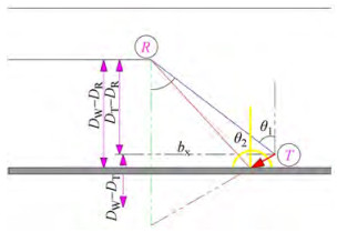 Figure 9 Pythagorean theorem for multipath bottom reflections
Suppose θ1 and θ2 are two consecutive reflection angles, the trigonometric angle d1 with θ1 and the trigonometric angle d2 with θ2.
$$ B=\sqrt{B_x^2+B_y^2} $$ (26) $$ B_y=D_T+D_R $$ (27) To calculate Bx, by considering two transient vertical line segments from points T and R that are parallel to each other and intersected by a blue diagonal line; as shown in Figure 10, the resulting angles will be equal in pairs (alternate angles) and θ = θ1.
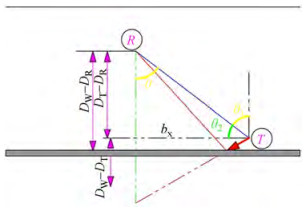 Figure 10 Alternate angles for calculation Bx
$$ B_x=\left(D_T-D_R\right) \tan \theta $$ (28) For every number of bottom reflections, n, between 1 and N, the propagation delay is calculated as:
$$ B_{y_n}=\left\lceil\frac{n}{2}\right\rceil 2 D_W-\left(D_T+(-1)^{n+1} D_R\right) $$ (29) $$ \begin{aligned} & B=\sqrt{B_x^2+B_y^2}= \\ & \left(\sqrt{\left(\left(D_T-D_R\right) \tan \theta\right)^2+\left(\left\lceil\frac{n}{2}\right\rceil 2 D_W-\left(D_T+(-1)^{n+1} D_R\right)\right)^2}\right) \end{aligned} $$ (30) $$ \begin{aligned} &T_{B n}= \\ &\left(\sqrt{\left(D_T-D_R\right)^2 \tan ^2 \theta+\left(\left\lceil\frac{n}{2}\right\rceil 2 D_W-\left(D_T+(-1)^{n+1} D_R\right)\right)^2}\right) / c \end{aligned} $$ (31) 4 Simulation results
The simulation results for the suggested channel model are presented in this section. MATLAB software is used for system design. Table 1 displays the simulation parameters.
Table 1 The simulation parametersParameters Values Transmitter depth (m) 40 Temperature, T (℃) 14 Salinity, S 35 Frequency, F (kHz) 12 Spreading factor, k 15 A pressure reflection coefficient of −1 is typical for normal incidence waves at the ocean's surface boundaries (Porta, 1998). In contrast, a pressure reflection value of 1 is typical for waves reflected from the ocean bottom. At the receiver, these even surface reflections contribute constructively, while odd surface and bottom reflections add destructively. Figure 11 shows the channel impulse response of multipath propagation between the source and receiver for two cases (a) horizontal communication at θ = 90° and (b) vertical communication at θ = 0°. It is found that the echo delay spread in the horizontal communication channel lasted more than 79 ms due to multipath propagation, while in a vertical communication channel, it was 333 msec. The large delay spread in the vertical case appears due to the short distance between the transmitter and receiver, so the direct path arrives in a short time while the multipath arrives at a long time. The multipath propagation causes signals to arrive at the receiver with different arrival times, amplitudes, and phases because of differences in the lengths of the original signal paths and the delay spread. The propagation delay of multipath relative to the direct path is a critical parameter in the underwater channel that affects system performance due to the delayed copies of the receiver introducing interference intersymbol.
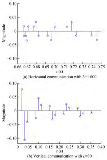 Figure 11 Communication CIR with DW = 50
The Bellhop simulator (Morozs et al., 2020) implements the same configuration parameters (DW, DT, DR, L = 1 000, f) as shown in Figure 12 for horizontal communication, where the red path relates to a signal that starts at the sea floor and gradually refracts upwards or diverges upward as they reach a steep positive sound speed gradient, where at the point they refract downwards. The green signal channel reaches the receiver by reflection from the water's surface and/or bottom. Because of the greater diversity of possible paths reflected off the sea surface and rough sea bottom, the black paths correspond to additional multipath components arriving at the receiver. When comparing the delay spread findings of the new suggested model in horizontal case where θ = 90° in Figure 11(a) 79 ms with the Bellhop simulator (Morozs, et al., (2020) in Figure 12(b) 78 ms in horizontal communication, the results seem to be coincident and in good agreement. The distinction is caused by the number of reflections utilized to indicate propagation delay.
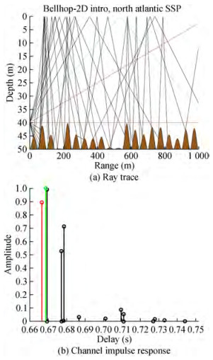 Figure 12 Bellhop's underwater multipath propagation system
To better understand how various parameters influence multipath propagation as shown by the delay spread and the calculated channel impulse response due to the delay spread is important factor that describe the impact of propagation delay in underwater environment and how we can use it in receiver design. These parameters include variations in transmitter-to-receiver distance, shallow water depth, and reflection number. The multipath pr opagation impact was shown to increase with depth while testing the suggested new model. Figure 13 depicts the delay spread as a function of depth: 79 ms at 50 m, 279 ms at 100 m, 535 ms at 150 m, and 824 ms at 200 m. The spatial difference in the speed of sound in water causes the sound to reflect off the surface and bottom, resulting in multipath propagation. Sound velocity is inversely proportional to temperature and pressure; therefore, it stays the same between 50 and 100 meters deep but slows down between 150 and 200 meters because of the lower temperatures there.
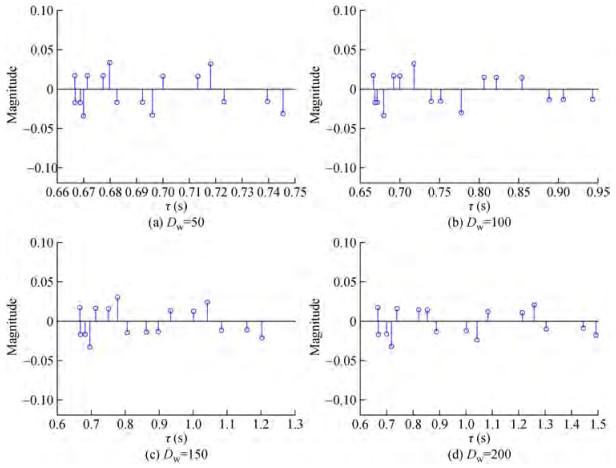 Figure 13 Impulse responses of communication channels at a range of shallow water depths (θ=90°, L=1 000)
Another test with varying distances between the transmitter and receiver revealed that the maximum delay spread is 0.48 s for channel lengths of 500 and 1 000 meters, respectively. Moreover, the 500 m range CIR seems to be more severe since some of its paths have comparable amplitudes to the direct path and the delay spread is more expansive, as seen in Figure 14.
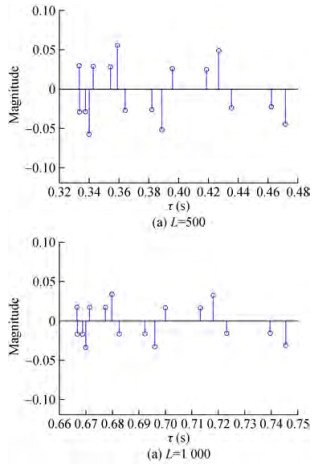 Figure 14 Impulse responses of communication channels with DW = 50, θ = 90° and varying ranges (L)
Figure 15 demonstrate the CIR at θ = 0° with a different number of reflections. The results show the delay spread was affected by an increasing number of reflections, 333 ms for N=10 and 666 ms for N=20, while the delay spread reached1 s and 1.3 s for N=30 and N=40, respectively.
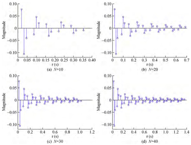 Figure 15 Impulse responses of communication channels with DW = 50, θ = 0° and different N
The following figures show the transmission loss for each path whose range is determined by the proposed geometrical model to describe the CIR taps for multipath propagation. It turns out that the model has adequately interpreted the characteristics of the communication channel for both horizontal and vertical communications. In Figures 16 and 17, the transmission loss increases with increasing multipath reflections for two cases, horizontal and vertical communications, respectively, reaching more than 81dB at 1.5 s and 81dB at 1.4 s. Transmission loss depends on how much sound spreads from spherical to cylindrical. Moreover, the attenuation increases by increasing contact distance, intensifying the power loss. In shallow waters bounded by the sea floor, the grazing angle also affects as rays that have grazing angles less than the decisive angle are almost completely reflected from the seabed, while sharp rays lose much reflection. These figures show that the transmission loss of the communication channel increases by increasing the number of echoes and the communication distance.
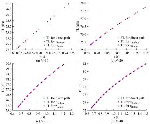 Figure 16 Transmission loss of horizontal communication channels with L=1 000, θ = 90°, DW = 50, and varying N
 Figure 17 Transmission loss of vertical communication channels with L=30, θ = 0°, DW = 50, and varying N
Figure 18 displays testing the transmission loss with different communication range between the transmitter and receiver. Since the propagation loss is a function of distance, as mentioned in the transmission loss equation, we find this clear in the figures below as the transmission loss increases with an increasing range at the same number of reflections.
 Figure 18 Transmission loss of horizontal communication channel with DW = 50, θ = 90° and varying lengths of (L)
5 Conclusions
In this work, a geometric model of the underwater communication channel environment based on the triangle that simulates multipath propagation delay in vertical and horizontal communication is proposed. It discusses the multipath effect induced by top and bottom reverberations and calculates a communication channel's impulse response and impact as the underwater depth and communication distance change. The simulation findings also reveal that increasing the communication distance and the amount of surface and bottom reflections increases the propagation losses. When the simulation results in terms of propagation delay are compared to the previous results, it becomes clear that the suggested model correctly represents the behavior of the communication channel in the shallow water situation.
Competing interest The authors have no competing interests to declare that are relevant to the content of this article. -
Figure 1 Multipath layout reflections in the communication channel
Figure 2 Locating the depth of the receiver
Figure 3 Multipath surface reflection using the Pythagorean theorem
Figure 4 multipath propagation for N=2
Figure 5 Equivalent model for multipath propagation when N=2
Figure 6 Surface reflections when N=n+2 with n=1
Figure 7 Surface reflections when N=2
Figure 8 Surface reflections when N=n+2 with n=2
Figure 9 Pythagorean theorem for multipath bottom reflections
Figure 10 Alternate angles for calculation Bx
Figure 11 Communication CIR with DW = 50
Figure 12 Bellhop's underwater multipath propagation system
Figure 13 Impulse responses of communication channels at a range of shallow water depths (θ=90°, L=1 000)
Figure 14 Impulse responses of communication channels with DW = 50, θ = 90° and varying ranges (L)
Figure 15 Impulse responses of communication channels with DW = 50, θ = 0° and different N
Figure 16 Transmission loss of horizontal communication channels with L=1 000, θ = 90°, DW = 50, and varying N
Figure 17 Transmission loss of vertical communication channels with L=30, θ = 0°, DW = 50, and varying N
Figure 18 Transmission loss of horizontal communication channel with DW = 50, θ = 90° and varying lengths of (L)
Table 1 The simulation parameters
Parameters Values Transmitter depth (m) 40 Temperature, T (℃) 14 Salinity, S 35 Frequency, F (kHz) 12 Spreading factor, k 15 -
Abdelkareem AE, Sharif BS, Tsimenidis CC (2016) Adaptive time varying Doppler shift compensation algorithm for OFDMbased underwater acoustic communication systems. Ad Hoc Networks. Elsevier B.V., 45: 104-119. https://doi.org/10.1016/j.adhoc.2015.05.011 Abdelkareem AE, Sharif BS, Tsimenidis CC, Neasham JA (2011) Time varying Doppler-shift compensation for OFDM-based shallow underwater acoustic communication systems. Proceedings of the 2011 IEEE Eighth International Conference on Mobile Ad-Hoc and Sensor Systems, 885-891. https://doi.org/10.1109/MASS.2011.105 Coates R (1994) Underwater acoustic communication. Sea Technology, 35(7): 41-47 Coates RFW (1991) Underwater acoustic systems.Ultrasonics. https://doi.org/10.1016/0041-624x(91)90035-7 Elamassie M, Miramirkhani F, Uysal M (2018) Channel modeling and performance characterization of underwater visible light communications.Proceedings of 2018 IEEE International Conference on Communications Workshops, 1-5. https://doi.org/10.1109/ICCW.2018.8403731 Hui J, Sheng X (2022) Reverberation Channel', in Underwater Acoustic Channel.Singapore: Springer Nature Singapore, 175-191. https://doi.org/10.1007/978-981-19-0774-6_6 John Heidemann B, Stojanovic M, Zorzi M (2012) Underwater sensor networks: applications, advances and challenges.Trans.R.Soc.A, 370:158-175. https://doi.org/10.1098/rsta.2011.0214. Lou Y, Ahmed N (2022) Basic Principles of Underwater Acoustic Communication.Underwater Communications and Networks.Cham: Springer International Publishing, 3-33. https://doi.org/10.1007/978-3-030-86649-5_1 Morozs N et al.(2020) Channel Modeling for Underwater Acoustic Network Simulation, 1-25. https://doi.org/10.24433/CO.1789096.v1. Porta D (1998) Underwater acoustic communications.Sea Technology, 39(2): 49-55. https://doi.org/10.1007/978-981-10-6963-5_288-1 Rawat M, Lall B, Srirangarajan S (2020) Angle of arrival distribution in an underwater acoustic communication channel with incoherent scattering.IEEE Access, 8:133204-133211. https://doi.org/10.1109/ACCESS.2020.3008602 Stojanovic M, Preisig J (2009) Underwater acoustic communication channels: propagation models and statistical characterization.IEEE Communications Magazine, 47(1): 84-89. https://doi.org/10.1109/MCOM.2009.4752682 Widiarti Y, Yuning W, Suwadi, Wirawan, Titiek S (2018) A geometrybased underwater acoustic channel model for time reversal acoustic communication.Proceeding-IEEE 2018 International Seminar on Intelligent Technology and Its Application, ISITIA, 345-350. https://doi.org/10.1109/ISITIA.2018.8711067 Zhou J et al.(2019) Study of propagation channel characteristics for underwater acoustic communication environments.IEEE Access, 79438-79445. https://doi.org/10.1109/ACCESS.2019.2921808 Zhu X, Wang CX, Ma R (2021) A 2D non-stationary channel model for underwater acoustic communication systems.IEEE Vehicular Technology Conference, 0-5. https://doi.org/10.1109/VTC2021-Spring51267.2021.9448976