Review on Seabed Trenches Induced by Mooring Lines and Analyses of Anchor Bearing Capacity
https://doi.org/10.1007/s11804-023-00333-x
-
Abstract
Mooring systems are usually adopted to position floating structures, including mooring lines and anchors, and directly determine the safety of floating structures. Seabed inspection reported that seabed trenches induced by mooring line-soil interaction appear in front of the anchor and reduce the anchor bearing capacity. This work first introduces the research progress of mooring line-soil interaction and seabed trenching simulation. Research about the suction anchor capacity in clay and sand is presented, and the seabed trench influence on anchor capacity is analyzed. For anchor analysis, this study gives a new perspective to analyze anchor installation and bearing capacity, i. e., structure-soil interface characteristic. Some common anchor types are analyzed. Results showed that seabed trench simulation is still needed to acquire trench 3D profiles, in which the mooring line-soil dynamic interaction cannot be ignored. At present, the trench influence is not considered in suction anchor design, making the design dangerous. For the anchor, the interface shear characteristics control the most unfavorable loading conditions. Thus, accurate interface parameters should be obtained for anchor analysis.-
Keywords:
- Seabed trench ·
- Mooring line ·
- Anchor ·
- Bearing capacity ·
- Interface shear
Article Highlights• The research progress of mooring line-soil interaction and seabed trenching simulation is introduced;• The suction anchor capacity in clay and sand is reviewed and the trench influence on anchor capacity is analyzed;• The anchor installation and bearing capacity are analyzed according to the structure-soil interface characteristic. -
1 Introduction
Marine resource exploitation leads to the rapid development of offshore structures (Zhou et al., 2019, 2021a; Zha et al., 2022). Floating structures, e.g., semisubmersible platforms, tension leg platforms, SPAR platforms, and floating production storage and offloading (FPSO) platforms, have been common types of oil and gas exploitation in deep sea in the past 50 years. In the last 15 years, floating wind turbines have developed rapidly, and largescale and deep-water wind turbines are an important development direction in the future. As shown in Figure 1, the world's first floating wind turbine, Hywind, was installed near the coast of Norway in 2009 (Madslien, 2009).
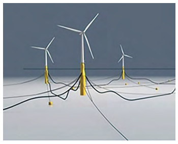 Figure 1 World's first floating wind turbine, Hywind (Madslien, 2009)
Floating structures require mooring systems for positioning, including mooring lines and anchors. A mooring system is the load transfer structure that connects the upper floating structures and the anchors. Its static and dynamic characteristics in seawater and seabed directly affect the service performance of the floating platform. The anchor transfers the load of the mooring line to the seabed, and its bearing capacity is the main concern for positioning floating platforms. Therefore, investigating the mooring line-seabed interaction and the anchor bearing capacity is necessary.
During the long service of mooring systems, some cases that affect the mooring system safety perhaps appear. In taut or semi-taut mooring systems, the upper floating structure drives the mooring line to move back and forth in large amplitude. The seabed soil is repeatedly cut by the embedded mooring line. The disturbed soil is then washed away by the turbulence, and the seabed trench appears. In 2014, seabed trenches appeared in front of the suction anchor in the Gulf of Guinea (Bhattacharjee et al., 2014), as shown in Figure 2. Owing to soil loss, the soil resistance acting on the anchor is reduced, resulting in an increase in the risk of anchor failure. In consideration of the mooring system safety, the mooring position was changed and the mooring lines and anchors were reinstalled
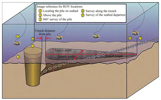 Figure 2 Schematic diagram of in-site seabed trench (Bhattacharjee et al., 2014)
After that, 12 seabed trenches have also been found around the FPSO mooring anchors in the North Sea (Hess, 2015). The site water depth is 140 m, and the seabed soil is soft clay. The latest report on seabed trenches is from Colliat et al. (2018). The water depth is about 1 300 m, and the seabed soil is soft clay. The report investigated the seabed trenches in front of the mooring system of FPSO and off-loading terminal buoys (OLTs) and found that a high mooring line tension leads to large seabed trenches and trench development rate.
The above reports present that seabed trenches widely exist in the mooring line touchdown area in front of the deeply embedded anchors, leading to a reduction in anchor capacity. The anchors tend to be pulled out under extreme loads, e.g., hurricanes or typhoons, resulting in a major accident in the floating platform.
Mooring anchors are the final structures to resist environment loads, and their bearing capacities originate from seabed soil resistance. Different anchor types are adopted according to the applicable water depth. Shallow-embedded anchors, such as gravity anchors, are of‐ ten used in shallow water catenary mooring systems. Deep embedded anchors, e.g., suction anchors, drag anchors, suction penetration plate anchors, and dynamic penetration anchors, are usually adopted in deep water. Anchor capacity is one of the main focuses in anchor design. The anchor capacity mobilizes from the interaction between the anchor and seabed soil; hence, its bearing capacity is affected by the anchor configuration and soil properties and related to the interface characteristics between anchor surface and soil(Rui et al., 2021a, 2021b).
This work aims to introduce the research progress on mooring system safety, including mooring lines and anchors. For mooring lines, this study mainly focuses on mooring line-soil interaction and its induced seabed trenches. For anchors, the suction anchor is introduced as the most widely used anchor type for floating structures. Its capacities in clay and sand are mainly investigated, and the trench influence on the anchor capacity is investigated. Furthermore, the anchor failure mode is found to be related to interface strength, including all kinds of anchors. From the perspective of the anchor surface-soil interface, the installation and service characteristics of different anchor types are analyzed.
2 Seabed trenches induced by mooring line-soil interaction
In this part, the research progress about mooring line-soil interaction is introduced, which is the trigger factor for trench formation (Sassi et al., 2017; Wang et al., 2020; Rui et al., 2020a). The seabed trenches induced by the mooring line-soil dynamic interaction are then analyzed. Finally, the studies about the seabed trench development are reviewed.
2.1 Mooring line-soil interaction
The formation of seabed trenches in the field is triggered by mooring line-soil interaction, and the trench profiles can be predicted according to the mooring line movement (Sassi et al., 2017; Wang et al., 2020). Thus, to reveal the mechanism of trench formation, the mooring line-soil interaction is one of the key points.
For the taut or semi-taut mooring system, the deeply embedded anchors, e.g., suction anchors, are recommended accordingly. In this case, part of the mooring line is embedded into the soil, which strongly interacts with the seabed soil. Rui et al.(2021c, 2021d) drew the diagram of anchor chain-soil interaction. Figure 3 shows the two sec-tions according to chain-soil interaction mode. The first section is the lying chain from the touch-down point to the dip-down point, wherein the chain direction is kept horizontal. The other one is the inverse catenary section fully embedded in the seabed, and its force analysis is relatively complex. The mooring line-soil interaction significantly influences the load magnitude and direction acting on the anchor padeye, indirectly changing the anchor failure mode.
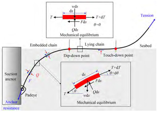 Figure 3 Diagram of anchor chain-soil interaction (Rui et al., 2021c)
The lying section is always kept horizontal, and its axial soil resistance F is proportional to chain unit weight W with friction coefficient μ. API-RP-2SK (2005), ISO-19901-7 (2005) and DNV-OS-E301 (2013) recommend μ= 1.0 under static/starting conditions and μ =0.7 under sliding conditions. The optimal value recommended by DNV-RP-E301 (2012) is 0.7. The mechanism and calculation method of chain axial resistance in the lying chain are relatively simple.
The embedded section is an inverse catenary segment completely embedded in the seabed, and its chain resistance analysis is more complex. Reese (1973), Gault & William (1974) and Vivatrat et al. (1982) discretized the embedded section into several elements and derived the equilibrium equation of soil resistance in two directions.
$$ T \frac{\mathrm{d} \theta}{\mathrm{d} s}=-Q+w \cos \theta $$ (1) $$ \frac{\mathrm{d} T}{\mathrm{~d} s}=F+w \sin \theta $$ (2) where T and θ are the mooring line tension and the tension inclined angle to the horizontal plane, w is the unit chain weight in water, and Q and F are the normal and axial soil resistances, respectively. The mooring line configuration in the seabed is mainly determined by normal resistance Q, while the partial tension of the mooring line is resisted by axial resistance F.
Degenkamp & Dutta (1989) carried out a series of model tests in saturated clay and proposed the calculation formula of chain axial and normal resistances.
$$ Q=E_{\mathrm{n}} \cdot d_{\mathrm{b}} \cdot d_l \cdot q $$ (3) $$ F=E_{\mathrm{t}} \cdot d_{\mathrm{b}} \cdot d_l \cdot f $$ (4) where db is the chain nominal diameter; dl is the line element length; q and f are the average normal and axial resistances, respectively; and Et and En are the chain axial and normal width parameters, respectively. On the basis of element test results, Et=8 and En=2.5 are recommended in clay. However, whether the value of Et and En depends on the clay properties is unclear.
Some numerical methods of simulating the mooring line-seabed interaction have been proposed. Wung et al. (1995) first proposed a 2-dimensional (2D) model using a nonlinear spring and two dashpots to simulate the dynamic interaction between the chain and seabed and calibrated the numerical tools with the centrifuge tests. The results showed that the chain-soil interaction can reduce the load acting on the padeye. Wang et al.(2010a, b) established a 3-dimensional (3D) static numerical model for investigating the mooring line load transfer considering chain-soil interaction. It is found that when the floating structures have lateral movement, there is a tension component perpendicular to the initial plane at the anchor padeye. Xiong et al. (2016, 2017) used the lumped mass method to simulate the chain-seabed dynamic interaction. The dynamic interaction considering the soil cyclic degradation is studied, and tension characteristics and chain touchdown area have been analyzed. Guo et al. (2016) proposed a model to simulate the multicomponent mooring line behavior considering chain-seabed interaction. The results showed that the increase in wire rope in moorings effectively limits the floating facility motion. Rui et al. (2021f) established a dynamic model to simulate the mooring line-seabed interaction, and investigated the mooring line load transfer. It is found that the inertial force and soil resistance contribute to the majority of mooring line tension variation. Although the above work established the basic mooring line-soil interaction, the complex soil properties were not considered in their analyses.
Sun et al.(2019a, 2019b) predicted chain configuration using the large deformation finite element method (coupled Eulerian-Lagrangian, CEL). In the simulation, the chain was considered as a series of cylinders, and the soil strain softening effect was considered. It is found that the chain mobilized friction coefficient is partial. However, the calculation based on the CEL method is time-consuming, which is not feasible for engineering applications.
The above work focused on the clay seabed. Some studies centered on chain-sand interaction. Choi et al. (2014) carried out the chain drag tests in sand under 1g condition. The test results showed that the passive resistance in front of the first link accounts for more than 81% of total resistance. On the basis of the assumption that the sand within a single link moves with the chain, a calculation method of chain axial resistance was proposed. Stanier et al. (2015) conducted a series of one-way and cyclic chain drag tests on sand seabed and obtained the relationship between axial resistance and displacement. The results showed that the chain axial friction coefficient in sand is greater than that of pipelines and plates due to the chain's passive soil resistance. Frankenmolen et al. (2016) studied the monotonic and cyclic interaction between chain and soil in calcareous sand based on centrifuge tests. The results showed that the chain friction coefficient of the embedded section is significantly lower than that of the lying section, and the friction coefficient increases with the cycle. Shen et al. (2019) established a finite element model to simulate chain profile in both clay and sand under dynamic conditions and found that the line tension decreases with the cycle numbers due to the gradual dig-in effect. Rui et al.(2021c, 2021d) designed a new chain-soil interaction apparatus to directly measure the chain monotonic and cyclic axial resistances under different confining stresses. Base on the test result, the expression of chain axial resistance was obtained to predict the chain profile in sand. Compared with the mooring chain-clay interaction, the chain behavior in sand is more complex (Rui et al., 2022b). However, the above research lacked a specific study of the chain-sand interaction mechanism.
2.2 Seabed trenches in the field
The mooring line-soil interaction in Section 2.1 is the basis of trench analysis because the formation of seabed trenches in the field is triggered by mooring line-soil dynamic interaction (Sassi et al., 2017; Wang et al., 2020). The mooring line repeatedly cuts into seabed, leading to the formation of seabed trenches near the mooring line touchdown area. Three cases of seabed trenches in the field have been reported since 2014. The first seabed trench was first discovered in 2014 (Bhattacharjee et al., 2014), and another two cases were reported in 2015 and 2018 (Hess, 2015; Colliat et al., 2018). The details about the trenches are summarized as follows:
Case 1: During the seabed survey of the Serpentina FPSO, the trenches were first found in the Gulf of Guinea (Bhattacharjee et al., 2014), as shown in Figure 4(a). The water depth of the FPSO was about 475 m. A single-point mooring system with nine mooring lines was adopted. The seabed soil was soft clay, and the padeye was located about 9 m below the mudline. A total of 9 trenches were found near the touch-down area. The trench depths were among 4-7 m. The trench lengths and widths were among 25-40 m and 4-10 m, respectively.
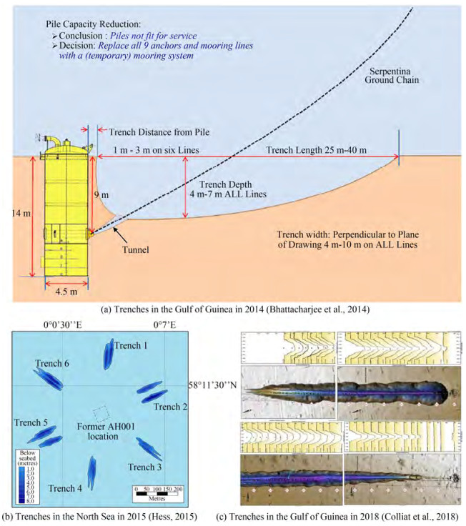 Figure 4 Trench profiles in the field from three reports
Case 2: As shown in Figure 4(b), 12 seabed trenches were reported around the FPSO named AH001 in the North Sea (Hess, 2015). The site water depth was about 140 m, and the soil was soft clay. The seabed trench depths in front of the piles were up to 10 m. The trench lengths were among 135-166 m, and the widths were 25-35 m.
Case 3: The latest report on the seabed trenches was from Colliat et al. (2018). The water depth was about 1 300 m, and the seabed soil was soft clay. Figure 4(c) shows two typical shapes of different trenches. Colliat et al. (2018) investigated the trenches for both the FPSOs and off-loading terminal buoys (OLTs). Taking the OLTs for example, 30-45 trenches were detected in situ. The anchor padeye depths were 9-12 m. The trench depths were 1-12 m. The trench lengths and widths were among 80-90 m and 1-13 m, respectively.
The main information about the trenches is summarized in Table 1. Some common characteristics are found in these cases. The semi-taut mooring strategy was mainly adopted and the anchor padeyes were embedded below the mudline. The cyclic movements of the upper structures lead to the chain repeatedly cutting into the soil. It is found that the soils are soft clay, which has low shear strength and is easy to be remoulded and removed by the flow. Though the trenches were discovered mainly in front of suction anchors and piles, the trench formation is not related to the anchor type. If the anchor padeye is embedded in the seabed, then the trench possibly appears near the mooring line touchdown area.
Table 1 Main information about seabed trenches discovered in the fieldTime Location Water depth (m) Soil property Platform Mooring strategy Trench numbers Padeye depth (m) Trench depth(m) Trench length (m) Trench width (m) 2014 Gulf of Guinea 475 soft clay Serpentina FPSO Semi-taut 9 9 4-7 25-40 4-10 2015 North Sea 140 soft clay AH001 FPF -- 12 ≥10 ≤10 135-166 25-35 2018 Gulf of Guinea 1 300 soft clay FPSO Semi-taut 60-90 12-15 0-5 90-100 0-7 OLT Semi-taut 30-45 9-12 1-12 80-90 1-13 2.3 Trench formation process and its simulation
As shown in Figure 5, Sassi et al. (2017) proposed possible phases for trench formation in the deep-sea. Wang et al. (2020) draw the specific schematic diagram for each phase as follows:
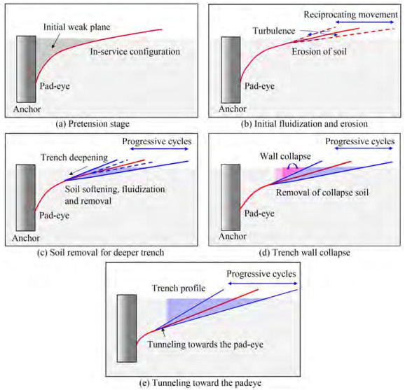 Figure 5 Typical formation phases of the trench (Wang et al., 2020)
Phase 1: An initial weak plane in the seabed is formed as the chain cuts through the soil.
Phase 2: The mooring line repeatedly cuts into the seabed and simultaneously induces current turbulence near the seabed, which induces the shallow soil erosion.
Phase 3: The softening, fluidization, and removal of seabed soil cause the shallow trench to become deeper and longer.
Phase 4: The trench wall becomes unstable and then collapses. The collapsed soil is gradually removed by the water turbulence and possible current.
Phase 5: An inner cavity formed at the trench bottom progressively moves toward the anchor padeye.
The seabed trench formation is a complex process involving mooring line movement, water disturbance, and soil collapse and migration. Among these, the mooring line seabed dynamic interaction is the trigger factor (Sassi et al., 2017; Versteele et al., 2017).
Sassi et al. (2017) conducted a series of centrifuge model tests to simulate the trench formation. It is found that the mooring line movement under cyclic loads play a key role in the trench formation. Versteele et al. (2017) proposed a 2D model for simulating the trench development using the analysis tool CASCI. However, the method adopted by the analysis tool CASCI is a static finite difference method that cannot consider the mooring line-seabed dynamic interaction. O'Neill et al. (2018) proposed a method for predicting the trench profile using the theoretical solution of the mooring line proposed by Neubecker & Randolph (1995). However, the above method did not consider the mooring line dynamic effect, so the prediction results were quite different from the actual trench profiles. Sun et al. (2020) established a numerical model base on a coupled Eulerian-Lagrangian (CEL) approach to simulate the trench formation. The chain is simulated as a series of cylindrical elements and the soil is modelled by a strain-softening Tresca material. Without the consideration of chain out-of-plane movements and hydrodynamic effects, a stable trench profile is formed after a few cycles. However, the mooring line dynamics is not considered in the method. Wang et al. (2020) established a 2D trench profile prediction method based on the finite element method. This model is the first to consider the mooring line-soil dynamic interaction. The trench profile predicted by the model is compared with the field data, which verified that the mooring line dynamics cannot be ignored in accurate trench profile prediction, as shown in Figure 6.
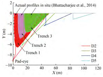 Figure 6 Comparisons of prediction trench profiles with the trench profiles in situ (Wang et al., 2020)
The seabed trench is formed due to the mooring line-soil dynamic interaction, and it is not related to the anchor type (Wang et al., 2020). The seabed trench is influenced by the anchor padeye depth, because it changes the mooring line embedded length and potential final trench depth. However, the seabed trench is not directly affected by anchor installation and bearing capacity. Seabed trenches change the anchor failure mode and reduce the anchor bearing capacity, which will be introduced in Section 3.1. In addition, seabed trenches do not affect the anchor installation.
3 Suction anchor research progress
A suction anchor is a steel thin-walled bucket structure and the most widely used anchor for floating structures in deep water. Its top is closed and equipped with a water valve, and its bottom is open. It has the advantages of accurate positioning, convenient construction, and the ability to withstand large vertical loads (Randolph & Gourvenec, 2011). It is also suitable for catenary and taut mooring systems. The suction anchor has a diameter of 4-6 m, and the ratio of length to diameter is generally between 3-6.
The suction anchor originates from the suction pile. It can be traced back to the 12 suction piles installed in the Gorm oilfield in 1981. The pile length is 8.5-9 m. In 1989, 16 suction piles were interconnected to form the foundation of the Gullfaks "C" concrete platform (Tjelta et al., 1990), which penetrated 22 m into the soft clay. In 1994, the suction anchor was first used in the CFD16-1 oilfield system in the Bohai Sea, China. In addition, the suction anchor was also used in the world's first offshore floating turbine, Hywind, which was installed on the Norwegian coast in 2009. The suction anchor has a diameter of 5 m, a length of 16 m, and a weight of 300 t.
3.1 Suction anchor capacity in clay
Suction anchors are widely adopted in clay seabed. The failure mode and bearing capacity of suction anchors in clay have been extensively studied(House & Randolph, 2001; Byrne & Houlsby, 2002; Aubeny et al., 2003; EI-sherbiny, 2005; Andersen et al., 2005; Aubeny & Murff, 2005; Rao et al., 2006; Zeinoddini et al., 2009; Kim et al., 2009; Liu et al., 2013; Guo et al., 2018).
House & Randolph(2001, 2002) proposed a 3D upper bound approach for the suction anchor capacity with horizontal or rotation components and evaluated the method accuracy by comparing it with the independent semi-anaytical finite element results. This method can predict the bearing capacity of suction anchors at different loading an‐ gles. Byrne & Houlsby (2002) carried out monotonic and cyclic loading tests at different rates to investigate the vertical response of suction caissons and discussed the relationship between monotonic and cyclic loads to reveal the key failure modes. Aubeny et al.(2003, 2005) proposed a simplified method to estimate the horizontal capacity of suction anchors based on an upper bound plasticity formulation to analyze the suction anchor capacity in uniform and linear undrained strength profiles. Liu et al. (2013) constructed the translational failure mode and force equilibrium equation of suction anchor based on the minimum force principle, and established the calculation method of suction anchor capacity considering different loading angles. The above studies focused on the ultimate capacity but ignored the anchor pulling-out process. Guo et al. (2018) carried out a series of model tests to investigate the short-term static capacities and the failure modes in clay and found that the loading angle decreases from 50.2° to 32.0°, the caisson's failure mode changes to a combined mode, and its corresponding capacity noticeably increases.
3.2 Suction anchor capacity in sand
Some progress has been made in the research about suction anchor capacity in sand, including in finite element calculation (Deng & Carter, 2000; Ahmed & Hawlader, 2014), experiment research (Bang et al., 2011; Gao et al., 2013; Jang & Kim, 2013), and theoretical analysis (Bang et al., 2006; Liu et al., 2015; Hirai, 2017; Guo et al., 2019; Xu et al., 2023).
Bang et al. (2011) conducted a series of centrifuge model tests to obtain the suction anchor capacity in sand, and proposed an analytical solution for horizontal pull-out capacity based on previous research results (Bang & Cho, 2001; Bang et al., 2006). Gao et al. (2013) studied the pull-out characteristics of suction anchors in sand under 1 g conditions and found that the anchor movement mode changes with the increasing loading inclined angle. When the load inclined angle changes from 0° to 60°, the capacity reduction is significant. Jang & Kim (2013) carried out centrifuge model tests to evaluate the horizontal capacity. The results showed that the equation derived from Rankine passive earth pressure equation has a good prediction of the test results. Liu et al. (2015) proposed an analytical model to predict the anchor capacity. The model adopted the soil resistance distribution proposed by Zhang et al. (2005) and Bang et al. (2006) to calculate the failure surface angle based on the minimum force principle. The anchor capacity in sand was mainly investigated by the model tests and numerical simulations. Never‐theless, the analytic method requires further development.
3.3 Suction anchor capacity considering the seabed trench
Seabed trenches have some influence on the anchor capacity, which is the focus of some studies.
Arslan et al. (2015) carried out finite element simulations to study the trench influence on the suction anchor capacity. The results showed that when the seepage path around the suction anchor is not considered, the trench influence on the passive suction at the anchor bottom is limited. Alderlieste et al. (2016) studied the suction anchor capacity in the presence of trenches and found that trenches reduce the anchor horizontal capacity. Therefore, it is suggested that the anchor padeye should be moved downward to improve the failure mode after the trench formation. Sassi et al. (2018) conducted a series of centrifuge model tests to explore the anchor capacity with and without trenches. The results showed that small trenches do not affect the mobilization of passive suction at the anchor bottom, which is consistent with the numerical results of Arslan et al. (2015). Feng et al. (2019) carried out a 3D finite element numerical simulation and explored the trench width influence on the anchor capacity. The anchor envelope surfaces with and without the trench were compared, and the findings showed that the anchor capacity decreases significantly when the load direction tends to be horizontal (Figure 7). Rui et al. (2022a) conducted a series of centrifuge model tests to investigate the trench influence on the anchor capacity in carbonate sand and captured the anchor movement and soil displacement through particle image velocimetry (PIV) analyses. It is found that the soil loss changes the anchor failure mode, and the anchor capacity decreases accordingly. Existing studies only investigated some special cases with the seabed trench, but the analysis framework considering the trench influence is still not established.
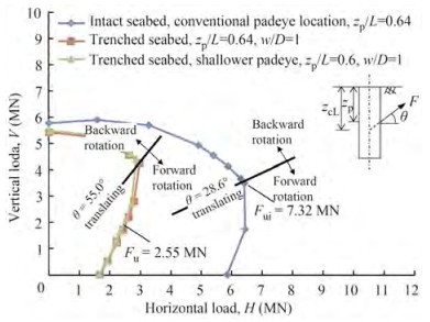 Figure 7 Effect of seabed trenching conditions on the inclined
3.4 Suction anchor capacity considering vertical cyclic loadings
Many experimental studies were conducted on suction anchor responses under axial cyclic loadings, e. g., Byrne & Houlsby (2002), Kelly et al. (2006), Bienen et al. (2018), and Jeong et al. (2020). The results showed that the behavior of suction anchors under axial cyclic loadings is complex, and the effects of cyclic loading amplitude, frequency, drainage condition, and loading history should be adequately considered in the design. However, the differential pressure (passive suction) acting on the caisson lid is not considered in the mainstream design codes (API, 2014; DNVGL, 2017; OWA, 2019). Using the finite element method, Thieken et al. (2014) and Cerfontaine et al. (2016) numerically studied the differential pressure development of uplifted suction anchors. It was found that the differential pressure can considerably increase the caisson uplift capacity. Tasan & Yilmaz (2019) used a fully coupled two-phase model and a hypo-plastic constitutive model to simulate the suction anchor responses under cyclic loadings, but the cycle number cannot be large due to efficiency problem. Senders (2008) proposed a kind of spring & damper model, which only needs a few parameters and shows high computational efficiency. But all the springs are elastic and linear, so this model cannot reflect the changes of caisson-soil interface strength and stiffness under cyclic loadings. In addition, the displacement and differential pressure accumulations of the suction anchor were not considered in the model. on the spring & damper model from Senders (2008), Zhou et al. (2021b) developed an elasto-plasticity model which can account for the cyclic loading effects, including the cyclic degradations of interface strength, stiffness and displacement accumulation, and the. The model diagram is shown in Figure 8.
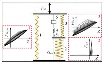 Figure 8 Spring & damper model (Zhou et al., 2021b)
4 Anchor behavior analysis based on the anchor-soil interface
The anchor bearing capacity is the ultimate structure to ensure the safety of the mooring system. The bearing capacity comes from the interaction between structure and seabed soil, so its capacity is not only affected by the anchor configuration and soil parameters, but also related to the steel-soil interface shear characteristics. In this part, a new perspective, the steel surface-soil interface, is provided to analyze the anchor behavior.
4-1 Steel surface-soil interface shear characteristics
The steel surface-soil interface interaction has an important influence on the anchor installation and service. White et al. (2012) and Boukpeti & White (2017) provide a critical state framework for result interpretation from interface shear tests on drained, partially drained and undrained conditions. The steel-clay interface shear τd can be expressed as:
$$ \tau_d=a\left(\sigma_n^{\prime}\right)^b \leqslant \mu_{\max } \sigma_n^{\prime} $$ (5) where σn' is the normal effective stress, μmax is the maximum interface coefficient of friction, and a and b are material constants varying with soil type. The steel-clay interface shear is related to various parameters, such as surface roughness (Ra), clay properties, clay drained condition, shear rate, etc. Martinez & Stutz (2019) studied the effects of shearing velocity, surface roughness, and overconsolidation ratio on the strength and deformation behavior of fine-grained soil-structure interface and pointed out that increasing surface roughness promotes shear strength under drained conditions. However, the expression of unified steel-clay interface strength considering various factors remains to be developed for rapid engineering design.
For steel-sand interface shear, the ratio of surface roughness to mean particle size (Ra/D50) is an important factor affecting interface behavior (Rao et al., 1998; Dove & frost, 1999; DeJong & frost, 2002; Dietz & Lings, 2006; DeJong & Westgate, 2009). Rao et al. (1998) explored the influence of different surface roughness and particle size on interface shear strength based on the interface direct shear apparatus and proposed that the interface normalized roughness can be characterized by Ra/D50. Lings & Dietz(2005, 2006) carried out an experimental study on interface shear. According to the normalized roughness Ra/D50, the roughness is divided into three grades (smooth, medium, and rough). The influence of normal stress on shear strength depends on the normalized roughness. DeJong & Westgate (2009) conducted a series of tests to explore the effects of different factors. It is found that if the interface is rough, the interface dilatancy/contraction behavior becomes significant. Meanwhile, the interface soil does not change significantly under smooth interface conditions.
Rui et al.(2018, 2021a, 2021b) conducted the large-displacement interface shear to investigate the monotonic and cyclic interface behaviour, and assessed the particle size and shape evolution(Rui et al., 2020b, 2021e). It is found that the particle breakage has a great influence on the interface strength under large-displacement shear. Zhou et al.(2020a, 2020b) investigated the cyclic degradation behavior of interface strength considering the effects from the previous large-displacement shear process and found that the shear displacement and shear path during the previous shear process have significant effects on the interface's cyclic degradation. Although the above studies analyzed the steel-sand interface interaction, the constitutive model still needs to be established.
4.2 Suction anchor
The suction anchor padeye is often located at about 2/3-3/4 of the anchor length below the mudline, and the suction anchor bears horizontal and vertical loads. During the installation of the suction anchor, the penetration resistance mainly includes the interface shear resistance and anchor tip resistance. Among these, the interface resistance is dominant; that is, it controls the penetration resistance.
API specification (API-RP-2SK, 2005) presents the failure envelope of the suction anchor in clay, as shown in Figure 9. Three failure modes of suction anchors have been discovered under combined loadings. When the loading angle is less than 15°, the anchor failure mode is controlled by horizontal soil resistance, and the horizontal bearing capacity is about 1.8 times the maximum vertical capacity. When the loading angle is greater than 40°-45°, anchor failure mode is controlled by the interface shear strength. When the loading angle is between 15°-40°, the anchor failure mode is controlled by the coupling effect. Among them, the anchor capacity is the lowest when the interface strength is controlled, which is the most unfavorable state in the project.
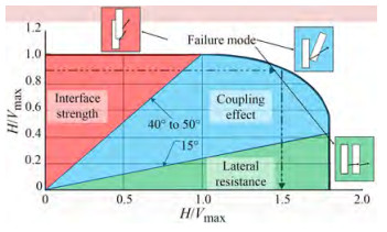 Figure 9 Failure envelope of suction anchor in clay (API-RP-2SK, 2005)
4.3 Vertically loaded anchor (VLA)
Vertically loaded anchor (VLA) is a new type of drag penetration plate anchor. Its installation method is similar to the traditional drag anchor. The anchor is slowly lifted, placed, and embedded onto the seabed along a certain trajectory through the cable length reduction or the installation ship movement. After the design depth is reached, the angle adjuster is excited, and the cable is adjusted to turn the anchor plate into a normal stress state. Under these conditions, the loading direction of mooring tension is perpendicular to the anchor plate plane. Different from traditional drag anchorsis that it can bear the vertical uplift bearing capacity, making it widely used in deep-water and semi-taut mooring systems.
Figure 10 shows the VLA installation and service state. The plate anchor is installed by exerting interface shear strength. In service, the anchor capacity is mobilized by normal soil resistance. Its characteristics are expressed as follows: during installation or recycling, the interface shear strength controls the minimum soil resistance, so the loading direction of the plate anchor is adjusted to be parallel to the tangential direction of the anchor plate to reduce the penetration resistance. During the service, the bearing capacity is controlled by the normal soil resistance, and the maximum bearing capacity of the plate anchor can be exerted by adjusting the load direction almost perpendicular to the normal direction of the plate anchor.
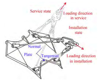 Figure 10 Installation and service status of a vertically loaded anchor
4.4 Suction embedded plate anchor
In 1999, Aker marine contractors used a suction anchor with a diameter of 4.5 m to penetrate the anchor plate, which verified the concept of suction embedded plate anchor (SEPLA) for the first time. SEPLA adopts the penetration method of suction anchor, and thus can be positioned more accurately than the drag plate anchor. After installation, its service mode is similar to that of the VLA. SEPLA needs to be pretensioned by tightening the cable after installation (Dove et al., 1998). In this process, the anchor chain cuts into the seabed, and the anchor plate rotates in the seabed to obtain the maximum bearing capacity. This process is called "keying" process, as shown in Figure 11. During this process, the penetration depth decreases due to plate rotation. O'Loughlin et al. (2006), Gaudin et al. (2006), and Song et al. (2009) studied the possible reduction of penetration depth during plate rotation by centrifuge tests and finite element results. Yu et al. (2009) studied anchor plate rotation in "keying" and considered that the loading eccentricity is one of the important factors influencing depth reduction. However, depth loss during "keying" still requires analytical analysis.
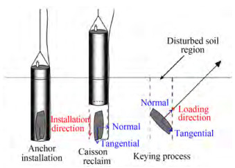 Figure 11 Installation and service status of a suction embedded plate anchor
For the SEPLA, the interface strength also plays an important role. During the anchor installation, the main resistance of SEPLA includes the tip resistance and interface shear resistance, corresponding to the minimum penetration resistance. After the "keying" process, the plate anchor rotates to make the loading almost perpendicular to the anchor plate to mobilize the maximum capacity. Consistent with the VLA, SEPLA also adjusts the plate direction perpendicular to the loading direction in service.
4.5 Dynamic penetration anchor
The dynamic penetration anchor penetrates into the seabed by the anchor's kinetic energy, among which the torpedo anchor is widely used in engineering (Han et al., 2020). Torpedo anchors consist of anchor shafts and wing plates, as shown in Figure 12. The torpedo anchor is low-cost and easy to install in deep water. However, since the chain is generally connected to the anchor top, the anchor may have rotation anchor in service, so the ratio of its bearing capacity to its weight is lower than that of other anchor types.
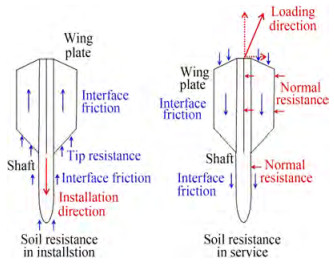 Figure 12 Distribution of soil resistance during torpedo anchor installation and service
The distribution of soil resistance during torpedo anchor installation and service is shown in Figure 12. In the installation process, when the torpedo anchor penetrates into the seabed vertically, its soil resistance includes end resistance and interface friction. When the anchor is in service, the loading direction is generally inclined upward. At that time, the force state of torpedo anchor is similar to that of suction anchor under an inclined load, which has three failure modes. When the loading angle is large, the failure mode of the torpedo anchor is mainly controlled by the interface strength.
5 Conclusions
This paper first introduces the research progress of mooring line-soil interaction and the seabed trenching simulation. Then, the research about the suction anchor capacity in clay and sand is presented, and the seabed trench influence on the anchor capacity is analyzed. For the anchor analysis, this paper gives a new perspective to analyze the anchor installation and bearing capacity, i.e., the structure-soil interface characteristic. Some common anchor types are analyzed. The main conclusions are as follows:
1) Seabed trench formation is triggered by the mooring line-soil interaction. In the simulation of trench formation, the mooring line-soil dynamic interaction cannot be ignored. The 2D trench profiles have been acquired, but the 3D profiles are still needed for anchor capacity analysis.
2) The trench mainly reduces the anchor's horizontal capacity and has minimal influences on the vertical capacity under undrained conditions. The trench influence is not considered in suction anchor design, which will make the design more dangerous.
3) For the anchor, the interface shear characteristics control the most unfavorable conditions. For all anchor designs, the interface shear resistance is mobilized to minimize the installation resistance, and normal resistance is exerted to maximize the capacity in service. Additional accurate interface parameters should be obtained for anchor analysis.
From the analysis above, the main shortcomings related to mooring lines and anchors are summarized as follows: (1) no methods can be used to predict the final 3D trench profiles at present, which have a great influence on anchor capacity; (2) trench formation involves complex processes that need to be revealed, and simulating this process is difficult; (3) the anchor capacity is reduced due to the seabed trench; thus, trench influence should be assessed, especially in long term service; and (4) interface strength controls the anchor failure mode and bearing capacity, but its mobilization feature in different anchor types is not clear.
Research topics in the future study include (1) accurate seabed trench profile prediction according to the mooring system configuration and soil properties; (2) trench formation mechanism related to mooring line dynamics, current/ turbulence, soil degradation and removal, etc.; (3) anchor capacity design considering the trench influence in the long term; and (4) failure mode analysis of different anchor types based on the soil-structure interface strength.
Competing interest The authors have no competing interests to declare that are relevant to the content of this article. -
Figure 1 World's first floating wind turbine, Hywind (Madslien, 2009)
Figure 2 Schematic diagram of in-site seabed trench (Bhattacharjee et al., 2014)
Figure 3 Diagram of anchor chain-soil interaction (Rui et al., 2021c)
Figure 4 Trench profiles in the field from three reports
Figure 5 Typical formation phases of the trench (Wang et al., 2020)
Figure 6 Comparisons of prediction trench profiles with the trench profiles in situ (Wang et al., 2020)
Figure 7 Effect of seabed trenching conditions on the inclined
Figure 8 Spring & damper model (Zhou et al., 2021b)
Figure 9 Failure envelope of suction anchor in clay (API-RP-2SK, 2005)
Figure 10 Installation and service status of a vertically loaded anchor
Figure 11 Installation and service status of a suction embedded plate anchor
Figure 12 Distribution of soil resistance during torpedo anchor installation and service
Table 1 Main information about seabed trenches discovered in the field
Time Location Water depth (m) Soil property Platform Mooring strategy Trench numbers Padeye depth (m) Trench depth(m) Trench length (m) Trench width (m) 2014 Gulf of Guinea 475 soft clay Serpentina FPSO Semi-taut 9 9 4-7 25-40 4-10 2015 North Sea 140 soft clay AH001 FPF -- 12 ≥10 ≤10 135-166 25-35 2018 Gulf of Guinea 1 300 soft clay FPSO Semi-taut 60-90 12-15 0-5 90-100 0-7 OLT Semi-taut 30-45 9-12 1-12 80-90 1-13 -
Ahmed SS, Hawlader BC (2014) Finite element modeling of inclined load capacity of suction caisson in with Abaqus/Explicit. Proceedings of the 24th International Offshore and Polar Engineering Conference, Busan, Korea Alderlieste E, Romp R, Kay S, Lofterød A (2016) Assessment of seafloor trench for suction pile moorings: a field case. Proceedings of Offshore Technology Conference, OTC, Houston, Texas, OTC-27035-MS. https://doi.org/10.4043/27035-MS Andersen KH, Murff JD, Randolph MF, Clukey EC, Erbrich CT, Jostad HP, Hansen B, Aubeny C, Sharma P, Supachawarote C (2005) Suction anchors for deep water applications. Proceedings of International Symposium on Frontiers in Offshore Geotechnics, ISFOG, Perth, 19-21. https://doi.org/10.1201/NOE0415390637.ch1 API (2014) Specific Requirements for Offshore Structures, Part 4-Geotechnical and Foundation Design Considerations API-RP-2SK (2005) Recommended Practice for Design and Analysis of Station Keeping Systems for Floating Structures Arslan H, Peterman BR, Wong PC, Bhattacharjee S (2015) Remaining capacity of the suction pile due to seabed trenching. The International Ocean and Polar Engineering Conference, ISOPE, Kona, Big Island, Hawaii, USA Aubeny CP, Han SW, Murff JD (2003) Inclined load capacity of suction caissons.International Journal for Numerical and Analytical Methods in Geomechanics, 27(14): 1235-1254. https://doi.org/10.1002/nag.319 Aubeny CP, Murff JD (2005) Simplified limit solutions for the capacity of suction anchors under undrained conditions.Ocean Engineering, 32:864-77. https://doi.org/10.1016/j.oceaneng.2004.10.006 Bang S, Cho Y (2001) Ultimate horizontal loading capacity of suction piles. Proceedings of the 11th International Offshore and Polar Engineering Conference, Stavanger, Norway, June. Bang S, Jones K, Kim YS, Kim KO, Cho Y (2006) Horizontal pullout capacity of embedded suction anchors in sand. Proceedings of the 25th International Conference on Offshore Mechanics and Arctic Engineering, Hamburg, Germany, June. https://doi.org/10.1115/OMAE2006-92006 Bang S, Jones KD, Kim KO, Kim YS, Cho Y (2011) Inclined loading capacity of suction piles in sand. Ocean Engineering, 38(7): 915-924. https://doi.org/10.1016/j.oceaneng.2010.10.019 Bhattacharjee S, Majhi SM, Smith D, Garrity R (2014) Serpentina FPSO mooring integrity issues and system replacement: unique fast track approach. Proceedings of Offshore Technology Conference, OTC, Houston, Texas, OTC-25449-MS. https://doi.org/10.4043/25449-MS Bienen B, Klinkvort RT, O'Loughlin C, Zhu F, Byrne BW (2018) Suction caissons in dense sand, Part II: vertical cyclic loading into tension. Géotechnique, 68(11): 953-967. https://doi.org/10.1680/jgeot.16.P.282 Boukpeti N, White DJ (2017) Interface shear box tests for assessing axial pipe-soil resistance. Géotechnique, 67(1): 18-30. https://doi.org/10.1680/jgeot.15.P.112 Byrne BW, Houlsby GT (2002) Experimental investigations of the response of suction caissons to transient vertical loading. Journal of Geotechnical and Geoenvironmental Engineering, 128(11): 926-939. https://doi.org/10.1061/(ASCE)1090-0241(2002)128:11(926) Cerfontaine B, Collin F, Charlier R (2016) Numerical modelling of transient cyclic vertical loading of suction caissons in sand. Géotechnique, 66(2): 121-136. https://doi.org/10.1680/jgeot.15.P.061 Choi Y, Kim B, Kwon O, Youn H (2014) Horizontal pullout capacity of steel chain embedded in sand. Advances in Soil Dynamics and Foundation Engineering, 500-508. https://doi.org/10.1061/9780784413425.051 Colliat JL, Safinus S, Boylan N, Schroeder K (2018) Formation and development of seabed trenching from subsea inspection data of deepwater gulf of Guinea moorings. Proceedings of Offshore Technology Conference, OTC, Houston, Texas, OTC-29034-MS. https://doi.org/10.4043/29034-MS Degenkamp G, Dutta A (1989) Soil resistances to embedded mooring line in soft clay. Journal of Geotechnical and Geoenvironmental Engineering, 115(10): 1420-1438. https://doi.org/10.1061/(ASCE)0733-9410(1989)115:10(1420) DeJong JT, Frost JD (2002) A multisleeve friction attachment for the cone penetrometer. Geotechnical Testing Journal, 25(2): 111-127. https://doi.org/10.1520/GTJ11355J DeJong JT, Westgate ZJ (2009) Role of initial state, material properties, and confinement condition on local and global soilstructure interface behavior. Journal of Geotechnical and Geoenvironmental Engineering, 135(11): 1646-1660. https://doi.org/10.1061/(ASCE)1090-0241(2009)135:11(1646) Deng W, Carter JP (2000) Inclined uplift capacity of suction caissons in sand. Proceedings, Offshore Technology Confonrence, OTC, Houston, Texas, 500-506. https://doi.org/10.4043/12196-MS Dietz MS, Lings ML (2006) Post peak strength of interfaces in a stress-dilatancy framework. Journal of Geotechnical and Geoenvironmental Engineering, 132(11): 1474-1484. https://doi.org/10.1061/(ASCE)1090-0241(2006)132:11(1474) DNVGL-RP-C212 (2017) Offshore Soil Mechanics and Geotechnical Engineering DNV-OS-E301 (2013) Position mooring-recommended practice DNV-RP-E301 (2012) Design and installation of fluke anchorsrecommended practice Dove JE, Frost JD (1999) Peak friction behaviour of smooth geomembrane-particle interfaces.Journal of Geotechnical and Geoenvironmental Engineering, 125(7): 544-555. https://doi.org/10.1061/(ASCE)1090-0241(1999)125:7(544) Dove P, Treu H, Wilde B (1998) Suction embedded plate anchor(SEPLA): A new anchoring solution for ultra-deepwater mooring. Proceedings of the Deep Offshore Technology Conference, DOT, New Orleans. EI-Sherbiny RM (2005) Performance of suction anchor anchors in normally consolidated clay. PhD Thesis. University of Texas at Austin Feng XW, Gourvenec S, White DJ (2019) Load capacity of caisson anchors exposed to seabed trenching.Ocean Engineering, 171:181-192. https://doi.org/10.1016/j.oceaneng.2018.09.027 Frankenmolen S., White D., O'Loughlin C (2016) Chain-soil interaction in carbonate sand. Proceedings of Offshore Technology Conference, OTC, Houston. https://doi.org/10.4043/27102-MS Gao YF, Qiu Y, Li B, Li DY, Sha CM, Zheng X (2013) Experimental studies on the anti-uplift behavior of the suction caissons in sand. Applied Ocean Research, 43: 37-45. https://doi.org/10.1016/j.apor.2013.08.001 Gaudin C, O'loughlin CD, Randolph MF, Lowmass AC (2006) Influence of the installation process on the performance of suction embedded plate anchors. Géotechnique, 56(6): 381-391. https://doi.org/10.1680/geot.2006.56.6.381 Gault J, William R (1974) Method for predicting geometry and load distribution in an anchor chain from a single point mooring buoy to a buried anchorage. Proceedings of the 6th Offshore Technology Conference, Houston, 309-318. https://doi.org/10.4043/2062-MS Guo Z, Jeng DS, Guo W, Wang LZ (2018) Failure mode and capacity of suction caisson under inclined short-term static and one-way cyclic loadings. Marine Georesources & Geotechnology, 36(1): 52-63. https://doi.org/10.1080/1064119X.2017.1279244 Guo Z, Wang LZ, Yuan F (2016) Quasi-static analysis of the multicomponent mooring line for deeply embedded anchors. Journal of Offshore Mechanics and Arctic Engineering, 138(1): 011302. https://doi.org/10.1115/1.4031986 Guo Z, Zhou WJ, Zhu CB, Yuan F, Rui SJ (2019) Numerical simulations of wave-induced soil erosion in silty sand seabeds. Journal of Marine Science and Engineering, 7(2): 52. https://doi.org/10.3390/jmse7020052 Han C, Liu J (2020) A review on the entire installation process of dynamically installed anchors. Ocean Engineering, 202: 107173. https://doi.org/10.1016/j.oceaneng.2020.107173 Hess (2015) DOC. No. ABD-DCO-RPT_01000 issued December 2015 Hirai H (2017) Evaluation of pullout load capacity of suction caissons in sand using a three-dimensional displacement approach.Marine Georesources & Geotechnology, 35(8): 1121-1134. https://doi.org/10.1080/1064119X.2017.1295120 House AR, Randolph MF (2001) Installation and pull-out of stiffened suction caissons in cohesive sediments. Proceedings of the 11th International Offshore and Polar Engineering Conference, Stavanger, Norway, June. ISO-19901-7 (2005) Petroleum and natural gas industries-specific requirements for offshore structures-Part 7: Station keeping systems for floating offshore structures and mobile offshore units. Jang YS, Kim YS (2013) Centrifugal model behavior of laterally loaded suction pile in sand.KSCE Journal of Civil Engineering, 17(5): 980-988. https://doi.org/10.1007/s12205-013-0011-z Jeong Y, Kim J, Manandhar S, Ha J, Park H, Kim D (2020) Centrifuge modelling of drained pullout and compression cyclic behavior of suction bucket.International Journal of Physical Modelling in Geotechnics, 20(2): 59-70. https://doi.org/10.1680/jphmg.18.00044 Kelly RB, Houlsby GT, Byrne BW (2006) Transient vertical loading of model suction caissons in a pressure chamber.Géotechnique, 56(10): 665-675. https://doi.org/10.1680/geot.2006.56.10.665 Kim KO, Kim YS, Cho Y, Bang S, Jones K (2009) Centrifuge model tests on suction piles in sand under inclined loading. Proceedings of the 19th International Offshore and Polar Engineering Conference, Osaka, Japan Lings ML, Dietz MS (2005) The peak strength of sand-steel interfaces and the role of dilation.Soils and foundations, 45(6): 1-14. https://doi.org/10.3208/sandf.45.1 Liu HX, Peng JS, Zhao YB (2015) Analytical study of the failure mode and pullout capacity of suction anchors in sand.Ocean System Engineering, 5(4): 279-299. http://dx.doi.org/10.12989/ose.2015.5.4.279 Liu HX, Wang C, Zhao YB (2013) Analytical study of the failure mode and pullout capacity of suction anchors in clay.Ocean System Engineering, 3(2): 79-95. http://dx.doi.org/10.12989/ose.2013.3.2.079 Madslien J (2009) Floating challenge for offshore wind turbine. BBC News Martinez A, Stutz HH (2019) Rate effects on the interface shear behaviour of normally and overconsolidated clay.Géotechnique, 69(9): 801-815. https://doi.org/10.1680/jgeot.17.P.311 Neubecker SR, Randolph MF (1995) Profile and frictional capacity of embedded anchor chains.Journal of Geotechnical Engineering, 121(11): 797-803. https://doi.org/10.1061/(ASCE)0733-9410(1995)121:11(797) O'Loughlin CD, Lowmass A, Gaudin CD (2006) Physical modelling to assess keying characteristics of plate anchors. Proceedings of the International Conference on Physical Modelling in Geotechnics, Hong Kong: CRC Press O'Neill M, Erbrich C, Mcnamara A (2018) Prediction of seabed trench formation induced by anchor chain motions. Proceedings of Offshore Technology Conference, OTC. https://doi.org/10.4043/29068-MS OWA. Offshore Wind Accelerator (2019) Suction Installed Caisson Foundations for Offshore Wind Randolph MF, Gourvenec S (2011) Offshore geotechnical engineering. CRC Press Randolph MF, House AR (2002) Analysis of suction caisson capacity in clay. Proceedings of the 34th Offshore Technology Conference, Houston, OTC14236, May 6-9, 2002, 1-11. https://doi.org/10.4043/14236-MS Rao KSS, Allam MM, Robinson RG (1998) Interfacial friction between sand and solid surfaces. Geotechnical Engineering, 131(2): 75-82. https://doi.org/10.1680/igeng.1998.30112 Rao SN, Latha KH, Pallavi B, Surendran S (2006) Studies on pullout capacity of anchors in marine clays for mooring systems. Applied Ocean Research, 28(2): 103-111. https://doi.org/10.1016/j.apor.2006.08.001 Reese L (1973) A design method for an anchor pile in a mooring system. Proceedings of the 5th Offshore Technology Conference, Houston, 209-218. https://doi.org/10.4043/1745-MS Rui SJ, Guo Z, Wang LZ, Zhou WJ, Shen KM (2018) Shear band between steel and carbonate sand under monotonic and cyclic loading. Proceedings of China-Europe Conference on Geotechnical Engineering, Vienna, Austria, August 12-17, 602-606. Rui SJ, Wang LZ, Shen KM, Guo Z, Zhou WJ, Li YJ (2020a) Numerical studies on seabed trench formation near the mooring foundation for floating wind turbines. Proceeding: International Offshore and Polar Engineering Conference, Shanghai, China, October 11-16, 1643-1650. Rui SJ, Guo Z, Si TL, Li YJ (2020b) Effect of particle shape on the liquefaction resistance of calcareous sands.Soil Dynamics and Earthquake Engineering, 137:106302. https://doi.org/10.1016/j.soildyn.2020.106302 Rui SJ, Wang LZ, Guo Z, Cheng XM, Wu B (2021a) Monotonic behavior of interface shear between carbonate sands and steel.Acta Geotechnica, 16:167-187. https://doi.org/10.1007/s11440-020-00987-9 Rui SJ, Wang LZ, Guo Z, Zhou WJ, Li YJ (2021b) Cyclic behavior of interface shear between carbonate sands and steel.Acta Geotechnica, 16:189-209. https://doi.org/10.1007/s11440-020-01002-x Rui SJ, Wang LZ, Guo Z, Zhang HJ, Zhou WJ (2021c) Axial interaction between anchor chain and sand.Part I: Monotonic loading test.Applied Ocean Research, 113(1): 102761. https://doi.org/10.1016/j.apor.2021.102761 Rui SJ, Wang LZ, Guo Z, Yang H, Zhou WJ (2021d) Axial interaction between anchor chain and sand.Part II: Cyclic loading test.Applied Ocean Research, 114(6): 102815. https://doi.org/10.1016/j.apor.2021.102815 Rui SJ, Guo Z, Si TL, Zhou WJ, Zha X (2021e) Particle shape influence on the deformation resistance of carbonate sands under drained condition.Soil Dynamics and Earthquake Engineering, 144:106688. https://doi.org/10.1016/j.soildyn.2021.106688 Rui S, Guo Z, Wang L, Liu H, Zhou W (2021f) Numerical investigations on load transfer of mooring line considering chain-seabed dynamic interaction.Marine Georesources & Geotechnology, 39(12): 1433-1448. https://doi.org/10.1080/1064119X.2020.1846646 Rui SJ, Guo Z, Wang LZ, Wang H, Zhou WJ (2022a) Inclined loading Capacity of Caisson anchor in South China Sea Carbonate Sand Considering the Seabed Soil Loss.Ocean Engineering, 260(15): 111790. https://doi.org/10.1016/j.oceaneng.2022.111790 Rui SJ, Guo Z, Wang LZ, Dou YZ, Zhou WJ, Zha X (2022b) Mobilization mechanism and calculation method of embedded chain axial resistance in sand.Ocean engineering, 263:112356. https://doi.org/10.1016/j.oceaneng.2022.112356 Sassi K, Kuo MYH, Versteele H, Cathie DN, Zehzouh S (2017) Insights into the Mechanisms of Mooring line Trench Formation. The Offshore Site Investigations and Geotechnics Conference, Society for Underwater Technology, SUT OSIG, London, UK, 10-12 September 2017 Sassi K, Zehzouh S, Blanc M, Thorel L, Cathie D, Puech A, ColliatDangus JL (2018) Effect of seabed trenching on the holding capacity of suction anchors in soft deepwater Gulf of Guinea clays. Proceedings of Offshore Technology Conference. OTC, Houston, Texas, OTC-28756-MS. https://doi.org/10.4043/28756-MS Senders M (2008) Suction Caissons in Sand as Tripod Foundations for Offshore Wind Turbines. PhD Thesis. University of Western Australia Shen K, Guo Z, Wang L (2019) Prediction of the whole mooring chain reaction to cyclic motion of a fairlead.Bulletin of Engineering Geology and the Environment, 78:2197-2213. https://doi.org/10.1007/s10064-018-1300-z Song Z, Hu Y, O'loughlin C D, Randolph M (2009) Loss in anchor embedment during plate anchor keying in clay.Journal of Geotechnical and Geoenvironmental Engineering, 135(10): 1475-1485. https://doi.org/10.1061/(ASCE)GT.1943-5606.0000098 Stanier S, White D, Chatterjee S, Brunning P, Randolph M (2015) A tool for ROV-based seabed friction measurement.Applied Ocean Research, 50:155-162. https://doi.org/10.1016/j.apor.2015.01.016 Sun C, Feng X, Neubecker S, Randolph M, Bransby M, Gourvenec S (2019a) Numerical study of mobilized friction along embedded catenary mooring chains.Journal of Geotechnical and Geoenvironmental Engineering, 145(10): 04019081. https://doi.org/10.1061/(ASCE)GT.1943-5606.0002154 Sun C, Feng X, Bransby M, Neubecker S, Randolph M, Gourvenec S (2019b) Numerical investigations of the effect of strain softening on the behavior of embedded mooring chains.Applied Ocean Research, 92:101944. https://doi.org/10.1016/j.apor.2019.101944 Sun C, Feng X, Bransby M, Neubecker S, Randolph M, Feng XW, Gourvenec S (2020) Numerical Investigations into Development of Seabed Trenching in Semitaut Moorings.Journal of Geotechnical and Geoenvironmental Engineering, 146(10): 04020098. https://doi.org/10.1061/(ASCE)GT.1943-5606.0002347 Tasan HE, Yilmaz SA (2019) Effects of installation on the cyclic axial behaviour of suction buckets in sandy soils.Applied Ocean Research, 91:101905. https://doi.org/10.1016/j.apor.2019.101905 Thieken K, Achmus M, Schröder C (2014) On the behavior of suction buckets in sand under tensile loads.Computers and Geotechnics, 60:88-100. https://doi.org/10.1016/j.compgeo.2014.04.004 Tjelta TI, Aas PM, Hermstad J, Andenaes E (1990) The skirt piled gullfaks C platform installation. Proceedings of Offshore Technology Conference, OTC. https://doi.org/10.4043/6473-MS Versteele H, Kuo MYH, Cathie DN, Sassi K, Zehzouh S (2017) Mooring line trenching-numerical simulation of progressive erosion. The Offshore Site Investigations and Geotechnics Conference, Society for Underwater Technology, SUT OSIG, London, UK Vivatrat V, Philip J, Albert A (1982) The influence of chain friction on anchor pile design. Proceedings of the 14th Offshore Technology Conference, Houston, 153-163. https://doi.org/10.4043/4178-MS Wang L, Guo Z, Yuan F (2010a) Three-dimensional interaction between anchor chain and seabed. Applied Ocean Research, 32(4): 404-413. https://doi.org/10.1016/j.apor.2010.09.001 Wang L, Guo Z, Yuan F (2010b) Quasi-static three-dimensional analysis of suction anchor mooring system. Ocean Engineering, 37(13): 1127-1138. https://doi.org/10.1016/j.oceaneng.2010.05.002 Wang LZ, Rui SJ, Guo Z, Gao YY, Zhou WJ, Liu ZY (2020) Seabed trenching near the mooring anchor: History cases and numerical studies. Ocean Engineering, 218: 108233. https://doi.org/10.1016/j.oceaneng.2020.108233 http://www.sciencedirect.com/science/article/pii/S0029801820311550 White DJ, Campbell ME, Boylan NP, Bransby MF (2012) A new framework for axial pipe-soil interaction, illustrated by shear box tests on carbonate soils. The Offshore Site Investigation and Geotechnics: Integrated Technologies-Present and Future, London, UK Wung CC, Litton RW, Mitwally HM (1995) Effect of soil on mooring system dynamics. Proceedings of the 27th Offshore Technology Conference, Houston, OTC-7672, 301-307.1 https://doi.org/10.4043/7672-MS Xiong LZ, White DJ, Neubecker SR, Zhao WH, Yang JM (2017) Anchor loads in taut moorings: The impact of inverse catenary shakedown. Applied Ocean Research, 67: 225-235. https://doi.org/10.1016/j.apor.2017.06.010 Xiong LZ, Yang JM, Zhao WH (2016) Dynamics of a taut mooring line accounting for the embedded anchor chains. Ocean Engineering, 121: 403-413. https://doi.org/10.1016/j.oceaneng.2016.05.011 Xu C, Jiang H, Xu M, Sun D, Rui SJ (2023) Calculation method for uplift capacity of suction caisson in sand considering different drainage conditions. Sustainability, 15(1): 454. https://doi.org/10.3390/su15010454 Yu L, Liu J, Kong XJ, Hu Y (2009) Three-dimensional numerical analysis of the keying of vertically installed plate anchors in clay. Computers and Geotechnics, 36(4): 558-567. https://doi.org/10.1016/j.compgeo.2008.10.008 Zeinoddini M, Mousavi A, Hobbi D (2009) Inclined load bearing capacity of suction caissons embedded in sands, ACSGE2009. Zha X, Guo Z, Wang LZ, Rui SJ (2022) A simplified model for predicting the accumulated displacement of monopile under horizontal cyclic loadings.Applied Ocean Research, 129:103389. https://doi.org/10.1016/j.apor.2022.103389 Zhang LY, Silva F, Grismala R (2005) Ultimate lateral resistance to piles in cohesionless soils.Journal of Geotechnical and Geoenvironmental Engineering, 131(1): 78-83. https://doi.org/10.1061/(ASCE)1090-0241(2005)131:1(78) Zhou WJ, Guo Z, Wang LZ, Liu JW, Rui SJ (2019) A novel T-Z model to predict the pile responses under axial cyclic loadings.Computers and Geotechnics, 112:120-134. https://doi.org/10.1016/j.compgeo.2019.04.027 Zhou WJ, Guo Z, Wang LZ, Li JH, Rui SJ (2020a) Sand-steel interface behaviour under large-displacement and cyclic shear.Soil Dynamics and Earthquake Engineering, 138:106352. https://doi.org/10.1016/j.soildyn.2020.106352 Zhou WJ, Guo Z, Wang LZ, Li JH, Rui SJ (2020b) Effect of Cyclic Jacking on Sand-pile Interface Shear Behaviour.Soil Dynamics and Earthquake Engineering, 141:106479. https://doi.org/10.1016/j.soildyn.2020.106479 Zhou WJ, Guo Z, Wang LZ, Li JH, Rui SJ (2021a) Simplified T-Z models for estimating the frequency and inclination of jacket supported offshore wind turbines.Computers and Geotechnics, 132(4): 103959. https://doi.org/10.1016/j.compgeo.2020.103959 Zhou WJ, Guo Z, Wang LZ, Zhang YR, Rui SJ (2021b) Numerical model for suction caisson under axial cyclic loadings.Ocean Engineering, 240(15): 109956. https://doi.org/10.1016/j.oceaneng.2021.109956