Automated Ship Berthing Guidance Method Based on Three-dimensional Target Measurement
https://doi.org/10.1007/s11804-023-00336-8
-
Abstract
Automatic berthing guidance is an important aspect of automated ship technology to obtain the ship-shore position relationship. The current mainstream measurement methods for ship-shore position relationships are based on radar, multisensor fusion, and visual detection technologies. This paper proposes an automated ship berthing guidance method based on three-dimensional (3D) target measurement and compares it with a single-target recognition method using a binocular camera. An improved deep object pose estimation (DOPE) network is used in this method to predict the pixel coordinates of the two-dimensional (2D) keypoints of the shore target in the image. The pixel coordinates are then converted into 3D coordinates through the camera imaging principle, and an algorithm for calculating the relationship between the ship and the shore is proposed. Experiments were conducted on the improved DOPE network and the actual ship guidance performance to verify the effectiveness of the method. Results show that the proposed method with a monocular camera has high stability and accuracy and can meet the requirements of automatic berthing.-
Keywords:
- Automated ship ·
- Automatic berthing ·
- Berthing guidance ·
- 3D measurement ·
- Neural networks ·
- Deep learning ·
- Position estimation
-
1 Introduction
Automated ships are fully automatic surface robots that can navigate on the water surface with the help of precise positioning and relevant sensors without remote control and have broad prospects in the military (Mazenc et al., 2002; Yu et al., 2012) and civil (Fu et al., 2015; Shuo et al., 2017) applica‐ tions. Research on automated ships has become the focus of artificial intelligence (AI) in various countries. Automated ship berthing guidance is one of the most difficult problems in auto‐ mated ship research. The task of berthing guidance is to con‐ trol the automated ship to travel to the berthing area on the shore. Its core technology aims to measure the positional rela‐ tionship between the ship and the shore in space.
The mainstream measurement methods mainly include de‐ tection techniques represented by various types of radar (Dickmann et al., 2015), multisensor fusion techniques (Shao et al., 2019), and visual detection techniques (Mi et al., 2021) to obtain the ship-shore position relationship in space. In the common application of detection technology, the berthing ar‐ ea is scanned with equipment, such as LIDAR and millime‐ ter wave radar, and then the acquired data are processed to measure the ship-shore position relationship. LIDAR is accu‐ rate but has a limited range, whereas millimeter wave radar has a large range but low accuracy. Automated ship berthing guidance problems include high requirements for range and accuracy; therefore, these types of equipment cannot meet the demand. Multisensor fusion technology refers to the ag‐ gregation of multiple sensors in the same device when a sin‐ gle sensor cannot meet the sensing requirements. This tech‐ nology is commonly used to provide sensing solutions that utilize Global Positioning System (GPS) and Inertial Mea‐ surement Unit(IMU) sensor fusion. The reliability of these methods depends heavily on sensory accuracy. High-preci‐ sion sensors, such as differential GPS, encounter limitations in meeting the requirements of berthing guidance. Vision in‐ spection technology involves the acquisition of images using a camera for measurement. Vision cameras have a price ad‐ vantage over radar and multisensor devices. In addition, the images contain rich and realistic information, which facili‐ tates the extraction of environmental information. (Lee et al., 2010) identified two targets in the berthing area using a vi‐ sion camera and then calculated the relationship between the ship's position in space and the shore. This finding indicates that visual inspection technology has become a mainstream measurement tool for automated ship berthing guidance.
Conventional visual inspection techniques adopt image segmentation in digital image processing (Cheng et al., 2021), and the main methods include threshold, cluster, and edge detection segmentation. For example, threshold segmen‐ tation can effectively separate the required information from the background (Dwina et al., 2018). Clustering segmenta‐ tion improves the detection speed (Hui et al., 2019). In addi‐ tion, a surface crack detection method based on the adaptive Canny and iterative threshold segmentation algorithms can effectively preserve the crack edges and obtain superior noise cancellation, thus reducing errors and missed detection (Song et al., 2016). These methods often require image preprocess‐ ing optimization for particular problems according to require‐ ments or environments. However, a limitation of convention‐ al visual inspection techniques is that specific optimization methods cannot be applied to all terminals because of the variations in the berthing areas' environment from terminal to terminal. With the improvement in computer performance in recent years, vision inspection technology has established a series of methods based on deep learning (Akbar et al., 2019). These methods stand out for their low cost, environ‐ mental adaptability, and other advantages.
The main method of guiding automated ships to berths through deep learning first identifies the target and then solves the ship-shore position relationship in space. Some scholars have proposed two-dimensional (2D) target recognition-based methods (Girshick et al., 2015; Liu et al., 2016; Redmon et al., 2016), such as region convolutional neural network (R-CNN), single-shot multi-box detector (SSD), and you only look once (YOLO). R-CNN extracts feature through convolutional neu‐ ral networks (CNNs), replacing the manual design of features in traditional methods. SSD and YOLO are based on the idea of direct regression, which regresses target classes and enclos‐ es borders at all locations in multiple locations of the input im‐ age. The measurement method based on 2D target recognition is fast. However, it usually needs to identify multiple targets and apply binocular vision technology (Li et al., 2018) to solve the ship-shore position relationship in space; thus, the stability and accuracy are not high. Other scholars have proposed meth‐ ods for the extraction of 2D features using CNNs to measure three-dimensional (3D) targets. Estimating depth maps (Tateno et al., 2017) and parallax (Chang et al., 2018) using CNNs are representative of these methods. Additionally, CNN can be used for six-dimensional target pose estimation (Zhao et al., 2020). The above methods are based on binocular vision tech‐ niques and use the computational results of the CNN to further create the 3D reconstruction of the target (Sun et al., 2020). They are more stable than measurements based on 2D target recognition, but ultimately require binocular cameras for their applications. Binocular cameras are limited in their measure‐ ment range by the baseline and have a higher computational complexity than conventional vision cameras. In addition, the remarkably complex CNN structure reduces the detection speed and fails to achieve real-time performance. Some stud‐ ies locate the center of an object in a 2D image through a CNN and then return it to the mass center of the object in the camera coordinate system to address these drawbacks, thus ac‐ complishing a 3D measurement of the target (Xiang et al., 2017; Tekin et al., 2018; Tremblay et al., 2018). These studies showed that high-precision 3D measurements could be achieved without using a binocular camera.
The above research shows that radar, GPS, and cameras are commonly used as perception devices in berthing guidance problems. Moreover, cameras have low costs and rich seman‐ tic information. The camera mainly uses a binocular camera and a single target or a monocular camera and multiple targets. The phenomenon of target loss easily occurs in the process of multitarget recognition; thus, the stability is poor. Binocular cameras are limited in their measurement range by the base‐ line and have high computational complexity. This research re‐ sults showed that the 3D target measurement method still has sufficient accuracy to be used for berthing guidance methods with monocular cameras and single targets. However, to date, these methods have been used to estimate robot poses and oth‐ er issues but cannot be directly applied to berthing guidance. Considering deep object pose estimation (DOPE), its output only contains the 3D coordinate information of the target, and this information cannot be directly used for berthing guidance. In addition, DOPE is complex for identifying custom targets, and the detection speed should be increased. This study im‐ proved the DOPE proposed by (Tremblay et al., 2018) and combined it with a path guidance model to propose an im‐ proved berthing guidance method for 3D measurement using a monocular camera to adapt to the actual berthing problem.
The method adopted a synthetic dataset and a lightweight CNN. It used the output of the network to calculate spatially subsurface ship-shore position relationships to accomplish au‐ tomated ship berthing guidance. The effectiveness of DOPE improvement was verified through experiments and compared with a single-target recognition method using a binocular cam‐ era. The implementation results showed that the berthing guid‐ ance method proposed in this paper has high stability and ac‐ curacy while ensuring real-time performance. This method can meet the requirements of automatic berthing.
2 Hardware solutions for berthing guidance
2.1 Problem description
Currently, mainstream berthing methods are out-of-berth stabilization, parallel access, and direct access to the berthing area. The berthing method used in this study is out-of-berth stabilization. By setting a virtual course and using AI and other techniques to navigate the automated ship to point L (L is 1.5 times the length of a ship), eventu‐ ally calming the automated ship, as shown in Figure 1.
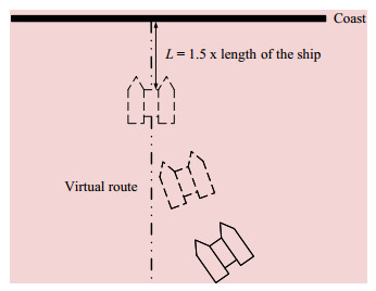 Figure 1 Berthing process
During berthing, the berthing guidance method requires real-time measurement of the ship-shore position relation‐ ship in three dimensions. The ship-shore position relation‐ ship is described in this study by the heading angle devia‐ tion Δθ and the deviation distance d, as shown in Figure 2.
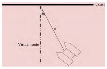 Figure 2 Ship-shore position relationship
2.2 Location of installed hardware
The target was placed on the shore, perpendicular to the horizontal plane. A vision camera was installed in the cen‐ tral position in front of the automated ship. Figure 3 shows the location of the installed hardware.
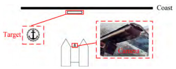 Figure 3 Location of installed hardware
3 Algorithm for ship-shore position relationship based on 3D target measurement
An image of the target located in the berthing area was collected in this study using a visual camera. The measure‐ ment algorithm calculates the ship-shore position relation‐ ship, sets the virtual route, and finally realizes automatic berthing guidance. The flow of the algorithm is shown in Figure 4. The measurement algorithm is divided into the following three modules: the CNN to extract the 2D key‐ points, the 2D keypoint regression to calculate the 3D co‐ ordinates of the automated ship and the target, and the cal‐ culation of the heading angle deviation and deviation dis‐ tance of the automated ship.
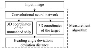 Figure 4 Algorithm flow
3.1 Lightweight convolutional neural network based on improved DOPE
DOPE applies the idea of migration learning to ex‐ tract target features in images using visual geometry group 19 (VGG19). Then it outputs six belief maps and six vector fields to detect target 2D keypoints (the belief map and vector field will be explained in detail in Sub‐ section 3.1(2)). Inspired by this idea, this study improves the original VGG19 for the real-time requirements of au‐ tomatic berthing. It deletes two belief maps and two vec‐ tor fields, improving the network's detection speed. As shown in Figure 5, the input of the improved CNN is an RGB image, and the output includes four belief maps and four vector fields. The number above a layer in the net‐ work indicates the number of channels in that layer.
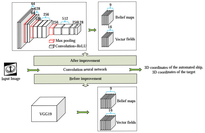 Figure 5 Structure of the improved network
3.1.1 Backbone network
The target of this study is an object with distinctive fea‐ tures. Results showed that the network depth does not re‐ markably improve accuracy. This study improved the VGG19 by removing seven convolutional layers and three fully connected layers. Two convolutional layers, namely Conv3_256 and Conv3_128, were then added at the end of the network (ConN_C is a convolutional layer with a channel number of C and a size of N × N). The improved network structures are listed in Table 1. All convolutional layers used ReLU as the activation function.
Table 1 Structure of the backbone networkNumber Layer Number Layer 1 Cov3_64 8 Cov3_256 2 Cov3_64 9 Cov3_256 3 Maxpool 10 Maxpool 4 Cov3_128 11 Cov3_512 5 Cov3_128 12 Cov3_512 6 Maxpool 13 Cov3_256 7 Cov3_256 14 Cov3_128 3.1.2 Belief maps and vector fields
The prediction of 2D keypoints relies on belief maps and vector fields. Every belief map has nine channels, corresponding to eight vertices and one centroid of the tar‐ get prediction box. Every
The vector field has a total of 16 channels, which correspond to the vectors formed by the eight vertices and cen‐ troid of the target, and each vector is estimated by two channels. A vector field aims to distinguish between differ‐ ent objects in the same image. DOPE designed six belief maps and six vector fields. Two belief maps and two vec‐ tor fields were deleted in this study. The network computa‐ tion was reduced, and the detection speed increased after the improvement. M1_2, m2_2, m3_2, and m4_2 are be‐ lief maps. Meanwhile, M1_1, m2_1, m3_1, and m4_1 are the vector fields. The network structures of the belief maps and vector fields are listed in Table 2.
Table 2 Structure of belief maps and vector fieldsName Layer Name Layer m1_1 Cov3_128 m1_2 Cov3_128 Cov3_128 Cov3_128 Cov3_128 Cov3_128 Cov1_512 Cov1_512 Cov1_16 Cov1_9 m2_1 Cov7_128 m2_2 Cov7_128 (m3_1, Cov7_128 (m3_2, Cov7_128 m4_1) Cov7_128 m4_2) Cov7_128 Cov7_128 Cov7_128 Cov7_128 Cov7_128 Cov1_128 Cov1_128 Cov1_16 Cov1_9 3.2 Calculation of 3D coordinates of automated ships and targets
The solution of the 3D coordinates of the automated ship, which is the target, requires the pixel coordinates of the 2D keypoints, and the prediction of the 2D keypoints is deter‐ mined by m4_1 and m4_2. The outputs of m4_1 and m4_2 are shown in Figure 6.
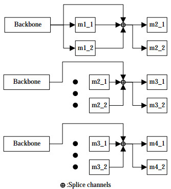 Figure 6 Outputs of m4_1 and m4_2
As shown in Figure 6, m1_1 and m1_2 use the output of the backbone as the input. The outputs of m1_1, m1_2, and the backbone network were used as the inputs of m2_1 and m2_2 after the channel splicing operation. The outputs of m2_1, m2_2, and the backbone network were used as inputs for m3_1 and m3_2 after the channel splicing opera‐ tion. The outputs of m3_1, m3_2, and the backbone net‐ work were used as the inputs of m4_1 and m4_2 after the channel splicing operation.
Fine fields of perception are obtained with each computation, and additional contextual information can be combined by splicing the channel operations to reduce ambiguity.
The outputs of m4_1 and m4_2 are ŷ1 and ŷ2, respective‐ ly, and the values of the target are y1 and y2. The loss func‐ tion is the mean squared error calculated between them, as expressed in the following equation:
$$ \mathrm{LOSS}=\left(\hat{y}_1-y_1\right)^2+\left(\hat{y}_2-y_2\right)^2 $$ (1) M4_1 and m4_2 do not directly reflect the predicted frame of the target. This study searched for local peaks in the nine channels of m4_2, and the pixel coordinates of the peak points were those of the 2D keypoints (eight vertices and one centroid) of different targets. A greedy assignment algorithm was then used to associate the vertices with the detected cen‐ troids. For each vertex, the latter step compared the vector field evaluated at the vertex with the direction from the ver‐ tex to each centroid and assigned the vertex to the closest centroid within the angular threshold of the vector.
Finally, the pixel coordinates of the 2D keypoints of each target detection frame were obtained, as shown by the red dots in Figure 7.
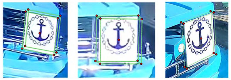 Figure 7 2D keypoints of the detection frame
Next, the pixel coordinates of the 2D keypoints must be transformed into 3D coordinates in space. According to the camera imaging model, the relationship between pixel coor‐ dinates p of the 2D image and 3D coordinates P in space can be expressed by the following equation:
$$ p = {\bf{K}}[{\bf{R}}\mid {\bf{T}}]P = {\bf{H}}P, $$ (2) where K is the camera internal reference matrix, [ R|T ] is the camera external reference matrix, R is the rotation ma‐ trix, T is the translation matrix, and H is the transforma‐ tion matrix of the required pixel coordinates to 3D coordi‐ nates.
The transformation of the pixel coordinates of 2D key‐ points to 3D coordinates in the world coordinate system relies on the algorithm shown in Figure 8.
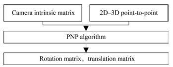 Figure 8 Flow of the pixel coordinate and 3D coordinate transformation algorithm
As presented in Figure 8, the calibrated camera in‐ ternal parameter matrix K and 2D–3D point pairs are substituted into Eq. (2), and the camera external pa‐ rameter matrix [ R|T ] is obtained in accordance with the perspective-n-point algorithm (Lepetit et al., 2009) by solving simultaneous equations. Subsequently, the trans‐ formation matrix H can be obtained.
3.3 Calculation of heading angle deviation and deviation distance
The heading angle deviation Δθ and the deviation dis‐ tance d are shown in Figure 9. The target is a rectangle per‐ pendicular to the horizontal in the berthing area; however, the detected prediction frame does not strictly satisfy these conditions. Therefore, the eight vertices of the prediction frame in this study are projected onto the horizontal plane α, where T is located to satisfy all the cases. T is the target center of mass; A, B, C, D, E, F, G, and H are the eight vertices of the prediction frame; C is the projection point of the cam‐ era on the horizontal plane. The 3D coordinates of the points above are all known conditions, and L is a point on the virtual route. The heading angle deviation Δθ and deviation distance d are calculated as follows:
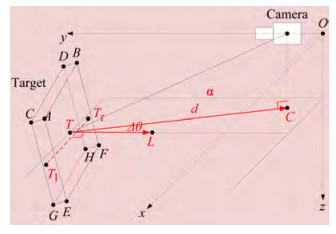 Figure 9 Heading angle deviation and deviation distance
$$ \Delta \theta=\arccos [(\boldsymbol{T C} \cdot \boldsymbol{T L}) /(|\boldsymbol{T C}| *|\boldsymbol{T L}|)] $$ (3) $$ d=|T C| $$ (4) The 3D coordinates of point L are obtained using the fol‐ lowing steps.
1) Notably, the projection coordinates of point A on the horizontal plane are (xa, ya, zT), those of point B on the horizontal plane are (xb, yb, zT), and so on to point H; the coordinates of point T are (xT, yT, zT).
2) Take a point Tl (xT l, yT l, zT l), where $ {x_{{T_l}}} = \left({{x_a} + {x_c} + {x_e} + {x_g}} \right)/4$, $y_{T_l}=\left(y_a+y_c+y_e+y_g\right) / 4 $, and $ {z_T}_l = {z_{{T^.}}}$
3) Take a point Tr (xT r, yT r, zT r), where ${x_{{T_r}}} = \left({{x_b} + {x_d} + {x_f} + {x_h}} \right)/4 $, $y_{T_r}=\left(y_b+y_d+y_f+y_h\right) / 4 $, and ${z_T}_l = {z_{{T^.}}} $
4) Take a point L (xL, yL, zL). The 3D coordinates of point L can be obtained by solving the following equation:
$$ \left\{\begin{array}{c} \boldsymbol{T} L \cdot \boldsymbol{T}_{\bf{l}} \boldsymbol{T}_{\boldsymbol{r}}=0 \\ |\boldsymbol{T} L|=1 \\ z_L=z_T \end{array}\right. $$ 4 Experimental results and analysis
The improved CNN is tested and compared with DOPE. In addition, the berthing guidance method proposed in this study is compared with the berthing guidance method based on 2D target recognition through real ship experi‐ ments. The experiments mainly tested the accuracy and sta‐ bility of berthing.
4.1 Experimental preparation
The hardware configuration of the CNN test platform is an Intel Xeon E3-1231 v3 processor, an NVIDIA Titan X image processor, and 16 GB of memory. The optimizer used in the training of the CNN was the AdaGrad optimization algorithm, and 200 training epochs were utilized. The batch size was 32, and the learning rate was 0.000 1. In addition, all input images were resized to 400 × 400 pixels.
The dataset used by CNN was synthetic data with a total of 10 000 images. Some images contained one target, whereas others did not. The training set was randomly gen‐ erated using the NViSII tool to the real data (Morrical et al., 2021). NViSII is a tool that places a 3D model of a target in a virtual scene and generates images with randomly chang‐ ing distractors, superimposed textures, backgrounds, target poses, lighting, and noise. The 3D model of the target had to be specially created for this case, with a total of 9 000 imag‐ es for the training set and 1 000 images for the test set.
The experimental platform included a test site and equip‐ ment. The experimental equipment was a self-developed un‐ derdriven automated ship with a length, width, and height of approximately 3, 1.8, and 1.6 m, respectively. The resolu‐ tion of the vision camera is 1 920 × 1 080 pixels, which is 0.8 m from the boat center. The test site was located in a wharf in the Hongkou District, Shanghai, China.
The experimental platform is shown in Figure 10. Figure 10 (a) illustrates the test site and target location, and Figure 10 (b) illustrates the experimental equip‐ ment and installation location.
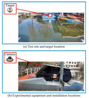 Figure 10 Experimental platform
4.2 Evaluation of automated ship berthing guidance methods based on 3D target measurement
Table 3 shows the validation of DOPE and CNN with the same test set, indicating that the proposed method is fast and has a comparable recognition success rate. The average recognition speed improved by approximately 100 ms. This finding shows that the present method is effective in improving DOPE.
Table 3 Statistics of convolutional neural network recognition resultsMethod Test set Total Number of successes Recognition rate Average speed (ms) DOPE with target 782 756 0.966 751 918 246 without target 218 217 0.995 412 844 Ours with target 746 715 0.958 445 04 152 without target 254 250 0.984 251 969 The live ship experiment compared this method with a berthing guidance method based on 2D target recognition. The test image used was an actual image captured using a vision camera on an automated ship. As a comparison ex‐ periment for this method, YOLOv3 was used for target de‐ tection, and binocular vision techniques were applied to cal‐ culate the 3D coordinates of the targets. The accuracy of the 3D coordinates of the targets detected using the two meth‐ ods was compared for each dimension.
As shown in Figures 11~13, the error between the mea‐ surement results of the two methods and the calibration value was calculated, and the results were fitted with a nor‐ mal distribution. The results show that the average error of the proposed method on the X-axis is approximately 5.6 cm, the error of YOLOv3 is approximately 8.7 cm, and the accuracy is improved by approximately 3.1 cm. The aver‐ age error of the proposed method is approximately 10.2 cm on the Y-axis, the error of YOLOv3 is approximately 18.3 cm, and the accuracy is improved by approximately 8.1 cm.The average error of the proposed method on the Z-axis is approximately 4.2 cm, the error of YOLOv3 is approxi‐ mately 7.6 cm, and the accuracy is improved by approxi‐ mately 3.4 cm.
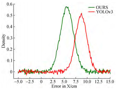 Figure 11 Error in target 3D coordinates on the X-axis
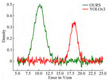 Figure 12 Error in target 3D coordinates on the Y-axis
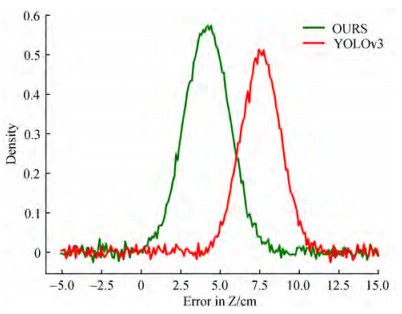 Figure 13 Error in target 3D coordinates on the Z-axis
Finally, this study used two guidance methods to control the automated ship to steer the berthing area with the same heading angle deviation Δθ and deviation distance d. The heading angle deviation Δθ and deviation distance d were recorded, and a curve was drawn during the experiment.
Figures 14 and 15 show that the measurement method based on YOLOv3 must identify two targets simultane‐ ously; therefore, the automated ship must swing the hull frequently. In the actual test, the oscillation of the head‐ ing angle deviation Δθ was larger than that of the proposed method. In addition, the proposed method can guide the automated ship to a distance of 4.5 m from the target (1.5 times the length of the automated ship, which is approximate‐ ly 3 m long) after approximately 30 s, whereas YOLOv3 re‐ quires approximately 60 s to complete the berthing guidance.
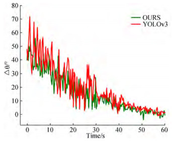 Figure 14 Heading angle deviation-time variation curve
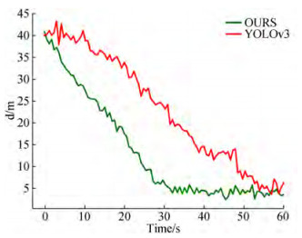 Figure 15 Deviation distance-time variation curve
The above experimental results show that the berthing guidance method proposed in this paper has high stability and accuracy while ensuring real-time performance, thereby addressing the requirements of automatic berthing.
5 Conclusions
The mainstream automated ship berthing guidance schemes are explored in this study. Considering the shortcomings of these schemes, an automated ship berthing guidance meth‐ od based on 3D target measurements is proposed. The backbone network of DOPE and the modified part of the convolutional layers are replaced. The experiments showed that the improved CNN had a fast detection speed. This study used the heading angle deviation and deviation distance as the target parameters to establish a berthing guidance mod‐ el. Furthermore, this study applied 3D information from DOPE to path guidance via the berth model. This method of using 3D target information for berthing guidance has rarely been attempted. Finally, the proposed method is compared with a single-target recognition method using a binocular camera. The experiments showed that the proposed method using a monocular camera demonstrated high stability and accu‐ racy, thus meeting the requirements of automatic berthing.
Research on automated ship berthing guidance methods mainly focused on 2D target recognition. This study ex‐ plored the current 3D measurement methods mainly used for robot pose estimation and applied them to automated ship berthing guidance. This attempt is relatively new, and its feasibility was experimentally verified. Thus, the introduced approach may be a new research direction for the problem of automated ship berthing guidance.
Acknowledgement: We express our appreciation to Shanghai SMUVision Smart Technology Ltd. for sharing the data used in this paper.Competing interest The authors have no competing interests to declare that are relevant to the content of this article. -
Figure 1 Berthing process
Figure 2 Ship-shore position relationship
Figure 3 Location of installed hardware
Figure 4 Algorithm flow
Figure 5 Structure of the improved network
Figure 6 Outputs of m4_1 and m4_2
Figure 7 2D keypoints of the detection frame
Figure 8 Flow of the pixel coordinate and 3D coordinate transformation algorithm
Figure 9 Heading angle deviation and deviation distance
Figure 10 Experimental platform
Figure 11 Error in target 3D coordinates on the X-axis
Figure 12 Error in target 3D coordinates on the Y-axis
Figure 13 Error in target 3D coordinates on the Z-axis
Figure 14 Heading angle deviation-time variation curve
Figure 15 Deviation distance-time variation curve
Table 1 Structure of the backbone network
Number Layer Number Layer 1 Cov3_64 8 Cov3_256 2 Cov3_64 9 Cov3_256 3 Maxpool 10 Maxpool 4 Cov3_128 11 Cov3_512 5 Cov3_128 12 Cov3_512 6 Maxpool 13 Cov3_256 7 Cov3_256 14 Cov3_128 Table 2 Structure of belief maps and vector fields
Name Layer Name Layer m1_1 Cov3_128 m1_2 Cov3_128 Cov3_128 Cov3_128 Cov3_128 Cov3_128 Cov1_512 Cov1_512 Cov1_16 Cov1_9 m2_1 Cov7_128 m2_2 Cov7_128 (m3_1, Cov7_128 (m3_2, Cov7_128 m4_1) Cov7_128 m4_2) Cov7_128 Cov7_128 Cov7_128 Cov7_128 Cov7_128 Cov1_128 Cov1_128 Cov1_16 Cov1_9 Table 3 Statistics of convolutional neural network recognition results
Method Test set Total Number of successes Recognition rate Average speed (ms) DOPE with target 782 756 0.966 751 918 246 without target 218 217 0.995 412 844 Ours with target 746 715 0.958 445 04 152 without target 254 250 0.984 251 969 -
Akbar J, Shahzad M, Malik MI, Ul-Hasan A, Shafait F. 2019. Runway detection and localization in aerial images using deep learning.In 2019 IEEE Digital Image Computing: Techniques and Applications (DICTA), 1-8.https://doi.org/ 10.1109/DICTA47822.2019.8945889 http://ieeexplore.ieee.org/stamp/stamp.jsp?tp=&arnumber=8945889 Chang JR, Chen YS. 2018. Pyramid stereo matching network.In Proceedings of the IEEE conference on computer vision and pattern recognition, 5410-5418.https://doi.org/ 10.1109/CVPR.2018.00567 http://ieeexplore.ieee.org/document/8578665 Cheng Y, Li B. 2021. Image segmentation technology and its application in digital image processing.In 2021 IEEE Asia-Pacific Conference on Image Processing, Electronics and Computers (IPEC), 1174-1177.https://doi.org/ 10.1109/IPEC51340.2021.9421206 http://en.cnki.com.cn/Article_en/CJFDTOTAL-HDZJ201011015.htm Dickmann J, Appenrodt N, Klappstein J, Bloecher HL, Muntzinger M, Sailer A, Brenk C. 2015. Making bertha see even more: Radar contribution.IEEE Access, 3:1233-1247. https://doi.org/ 10.1109/ACCESS.2015.2454533 Dwina N, Arnia F, Munadi K. 2018. Skin segmentation based on improved thresholding method.In 2018 IEEE International ECTI Northern Section Conference on Electrical, Electronics, Computer and Telecommunications Engineering (ECTI-NCON), 95-99.https://doi.org/ 10.1109/ECTI-NCON.2018.8378289 http://www.onacademic.com/detail/journal_1000040808610210_842d.html Fu MY, Xu YJ, Wang YH. 2015. Cooperation and collision avoidance for multiple DP ships with disturbances.In 2015 IEEE 34th Chinese Control Conference (CCC), 4208-4213.https://doi.org/ 10.1109/ChiCC.2015.7260288 http://ieeexplore.ieee.org/stamp/stamp.jsp?tp=&arnumber=7260288 Girshick R, Donahue J, Darrell T, Malik J. 2015. Region-based convolutional networks for accurate object detection and segmentation.IEEE Transactions on Pattern Analysis and Machine Intelligence, 38(1): 142-158.https://doi.org/ 10.1109/TPAMI.2015.2437384 http://fcv2011.ulsan.ac.kr/files/announcement/513/rcnn_pami.pdf Hui Y, Han Y. 2019. Advanced density peak and K-means clustering on image segmentation.In 2019 IEEE 4th Advanced Information Technology, Electronic and Automation Control Conference (IAEAC), 1:2740-2744.https://doi.org/ 10.1109/IAEAC47372.2019.8997758 http://ieeexplore.ieee.org/stamp/stamp.jsp?tp=&arnumber=8997758 Lee SD, Tzeng CY, Kehr YZ, Huang CC, Kang CK. 2010. Autopilot system based on color recognition algorithm and internal model control scheme for controlling approaching maneuvers of a small boat.IEEE Journal of Oceanic Engineering, 35(2): 376-387. https://doi.org/ 10.1109/JOE.2010.2043753 Lepetit V, Moreno-Noguer F, Fua P. 2009. EP n P: An accurate O (n) solution to the P n P problem.International Journal of Computer Vision, 81:155-166. https://doi.org/ 10.1007/s11263-008-0152-6 Li TY, Zhu HB. 2018. Research on model control of binocular robot vision system.In 2018 IEEE Chinese Automation Congress(CAC), 1794-1797.https://doi.org/ 10.1109/CAC.2018.8623756 http://ieeexplore.ieee.org/stamp/stamp.jsp?tp=&arnumber=8623756 Liu W, Anguelov D, Erhan D, Szegedy C, Reed S, Fu CY, Berg AC. 2016. SSD: Single shot multibox detector.In Proceedings of Computer Vision-ECCV, 2016: 14th European Conference, Amsterdam, Part Ⅰ, 21-37.Springer International Publishing.10.48550/arXiv.1512.02325https://doi.org/ 10.48550/arXiv.1512.02325 Mazenc F, Pettersen K, Nijmeijer H. 2002. Global uniform asymptotic stabilization of an underactuated surface vessel.IEEE Transactions on Automatic Control, 47(10): 1759-1762. https://doi.org/ 10.1109/TAC.2002.803554 Mi C, Huang Y, Fu C, Zhang Z, Postolache O. 2021. Vision-based measurement: actualities and developing trends in automated container terminals.IEEE Instrumentation & Measurement Magazine, 24(4): 65-76.https://doi.org/ 10.1109/MIM.2021.9448257 http://ieeexplore.ieee.org/stamp/stamp.jsp?tp=&arnumber=9448257 Morrical N, Tremblay J, Lin Y, Tyree S, Birchfield S, Pascucci V, Wald I. 2021. NViSII: A scriptable tool for photorealistic image generation.arXiv preprint arXiv: 2105.13962.https://doi.org/ 10.48550/arXiv.2105.13962 http://www.xueshufan.com/publication/3165524250 Redmon J, Divvala S, Girshick R, Farhadi A. 2016. You only look once: Unified, real-time object detection.In Proceedings of the IEEE Conference on Computer Vision and Pattern Recognition, 779-788.https://doi.org/ 10.1109/CVPR.2016.91 http://ai2-website.s3.amazonaws.com/publications/YOLO.pdf Shao G, Ma Y, Malekian R, Yan X, Li Z. 2019. A novel cooperative platform design for coupled USV-UAV systems.IEEE Transactions on Industrial Informatics, 15(9): 4913-4922. https://doi.org/ 10.1109/TII.2019.2912024 Shuo J, Yonghui Z, Wen R, Kebin T. 2017. The unmanned autonomous cruise ship for water quality monitoring and sampling.In 2017 IEEE International Conference on Computer Systems, Electronics and Control (ICCSEC), 700-703.https://doi.org/ 10.1109/ICCSEC.2017.8447040 http://www.onacademic.com/detail/journal_1000040882808810_e505.html Song Q, Lin GY, Ma JQ, Zhang HM. 2016. An edge-detection method based on adaptive canny algorithm and iterative segmentation threshold.In IEEE 2016 2nd International Conference on Control Science and Systems Engineering (ICCSSE), 64-67.https://doi.org/ 10.1109/CCSSE.2016.7784354 http://ieeexplore.ieee.org/stamp/stamp.jsp?tp=&arnumber=7784354 Sun ZY, Wang LH, Liu LQ. 2020. Three-dimensional reconstruction algorithm based on inverse perspective transformation.In 2020 IEEE International Conference on Big Data, Artificial Intelligence and Internet of Things Engineering (ICBAIE), 221-225.https://doi.org/ 10.1109/ICBAIE49996.2020.00053 http://ieeexplore.ieee.org/stamp/stamp.jsp?tp=&arnumber=9196236 Tateno K, Tombari F, Laina I, Navab N. 2017. CNN-SLAM: Real-time dense monocular slam with learned depth prediction.In Proceedings of the IEEE conference on computer vision and pattern recognition, 6243-6252.https://doi.org/ 10.1109/CVPR.2017.695 http://www.xueshufan.com/publication/2952280228 Tekin B, Sinha SN, Fua P. 2018. Real-time seamless single shot 6d object pose prediction.In Proceedings of the IEEE conference on computer vision and pattern recognition, 292-301.https://doi.org/ 10.1109/CVPR.2018.00038 http://ieeexplore.ieee.org/stamp/stamp.jsp?tp=&arnumber=8578136 Tremblay J, To T, Sundaralingam B, Xiang Y, Fox D, Birchfield S. 2018. Deep object pose estimation for semantic robotic grasping of household objects.arXiv preprint arXiv: 1809.10790.https://doi.org/ 10.48550/arXiv.1809.10790 http://www.xueshufan.com/publication/2893763910 Xiang Y, Schmidt T, Narayanan V, Fox D. 2017. Posecnn: A convolutional neural network for 6d object pose estimation in cluttered scenes.arXiv preprint arXiv: 1711.00199.https://doi.org/ 10.48550/arXiv.1711.00199 http://doc.paperpass.com/patent/arXiv171100199.html Yu R, Zhu Q, Xia G, Liu Z. 2012. Sliding mode tracking control of an underactuated surface vessel.IET Control Theory & Applications, 6(3): 461-466.https://doi.org/ 10.1049/iet-cta.2011.0176 http://ieeexplore.ieee.org/stamp/stamp.jsp?tp=&arnumber=6159170 Zhao W, Zhang S, Guan Z, Zhao W, Peng J, Fan J. 2020. Learning deep network for detecting 3d object keypoints and 6d poses.In Proceedings of the IEEE/CVF Conference on Computer Vision and Pattern Recognition, 14134-14142.https://doi.org/10.1109/CVPR42600.2020.01414 http://www.xueshufan.com/publication/3034390099