Recent Developments in Fatigue Assessment of Ships and Offshore Structures
https://doi.org/10.1007/s11804-022-00301-x
-
Abstract
A review is provided of various approaches that have been adopted recently to assess the fatigue of ships and offshore structures. The relevant fatigue loading is reviewed first, focusing on the successive loading and unloading of the cargo and the transient loadings. The factors influencing fatigue strength are discussed, including the geometrical parameters, material, residual stress, and ones related to the environment. Different approaches for fatigue analyses of seam-welded joints are covered, i.e., the structural stress or strain approach, the notch stress or strain approach, notch intensity approach, and the crack propagation approach.Article Highlights• Factors influencing fatigue strength, including geometry, material, residual stresses and environment, are discussed;• Various approaches for fatigue analyses are reviewed. -
1 Introduction
Ships and offshore structures are subjected to a large number of cyclic loadings during their service lives, which may lead to fatigue failure of their structural components or even of the whole structure, which implies loss of lives and property and has a negative environmental impact. Well-known accidents associated with fatigue are the fracture of a series of Liberty ships, the collapse of the platform Alexander L. Kielland (France 2019; Moan 1985), the crack in the deck of the tanker Castor (Mahmoud and Dexter 2005) or the failure of the tanker Prestige (BMA 2004), to name a few. Even though some accidents cannot be directly attributed to fatigue, it is often a contributing factor. In addition to severe accidents, the fatigue cracks appearing in structural components after some years of service are also of concern because the integrity and safety of structures are degraded, and costly repairs have to be performed. These accidents and fatigue cracks motivate extensive studies in this field. Nowadays, fatigue has been a significant concern in ships and offshore structures' design, manufacturing, and operation.
Although classification societies or other institutes have established various codes to deal with the fatigue of materials and welded joints in ships and offshore structures, challenges remain. Larger and larger ships are constructed to improve energy efficiency and reduce the capital cost and manning cost per deadweight tone (Pedersen 2015). High tensile strength steel and thick plates are typically used in these ships. The former can improve the static strength but cannot improve the fatigue strength of welded joints (Maddox 1991). The welded joints made of thick plates have lower fatigue strength. The whipping and springing vibrations of the hull-girder, which significantly affect the fatigue strength, can occur more frequently because of the large bow flare and high hull flexibility for newly designed ships (Rajendran et al. 2016).
The main challenge of offshore structures is that newly discovered resources are generally in much harsher environments, e.g. great water depth or arctic waters, than today's ones (Pedersen 2015). It implies that more consideration should be given to the fatigue strength of structures. In addition, new types of offshore structures, e.g. fixed, or floating offshore wind turbines, are deployed to harvest offshore renewable energies, whose fatigue strength assessment may need more effort since they are subjected to more complex fatigue loadings (Zwick and Muskulus 2016).
The fatigue strength assessment methods are also under development. Fatigue failure of welded ships and offshore structures originates from the weld joints rather than the base metal. The nominal or structural hot spot stress approach for welded joints was developed mainly based on experiments and had some limits in practical application. Some approaches with sound theoretical background were then proposed as alternatives. Besides, extensive efforts are given to investigate the effects of various factors on the fatigue strength of welded joints, e.g. weld geometry, residual stresses, material, and environment. Modelling these effects in fatigue strength assessment has been a major topic.
The demand for accurate fatigue strength assessment for ships and offshore structures is strong, while the existing assessment approaches' capability is still insufficient. The gap between the demand and capability motivates the present study to clarify state of the art and possible future works to improve the assessment approaches. Note that the fatigue failure is a significant failure mode for almost all engineering structures subjected to cyclic loading. Therefore, many studies performed in other industry sectors are also valuable for the ship and offshore industry. The relevant studies on fatigue are reviewed, mainly those published in recent years. Due to a large number of relevant studies, some specific topics are left behind.
The paper is organized in the following manner. Section 2 briefly reviews the relevant fatigue loadings, especially the successive loading and unloading of the cargo and the transient loadings. The factors influencing the fatigue strength of welded joints are discussed in Section 3. Section 4 covers various approaches for fatigue analyses of seam-welded joints, including some S-N curve approaches and the crack propagation approach. Conclusions are summarized in Section 5.
2 Loading
The fatigue loading is the crucial input factor for any fatigue analysis. For ship structures, the cyclic loading can be divided into three categories according to their frequency or period (Fricke, 2017):
• Loads due to varying loading conditions,
• Loads in a seaway,
• Propulsion-induced loads and vibrations.
Conventionally, only the wave frequency stress in the order of 0.1 Hz was considered in fatigue design codes. The change of loading conditions results in fluctuating static stresses (still-water loading effect) for long periods (Guedes Soares and Moan 1988). Stress cycles with relatively large ranges are formed, see Figure 1. These stress cycles are usually from hundreds to thousands during the service life, depending on the ship type and voyage distance. The higher frequency stresses caused by the propulsion system, wave impacts (slamming) or oscillating wave loads are also relevant for fatigue (Corak et al. 2015b). The latter two phenomena are known as whipping and springing of the hull girder. The frequency is usually in the order of 1 Hz (Wang and Guedes Soares 2017).
 Figure 1 LCF loading for ship structures (Dong et al. 2021b)
Since the wave frequency fatigue loading on ships and offshore structures was extensively investigated and the method for its prediction is well-established (i. e., Guedes Soares 1990; Guedes Soares and Moan 1991), the present review focuses on the successive loading and unloading of the cargo and the transient loadings, i.e., those belonging to the first and third category. Their loading cycles are known to have significant ranges.
The significant stress cycles may be the most damaging events of the fatigue process. Experiments have shown that micro-cracks are initiated immediately within the first early cycles in plain and notched specimens in the Low Cycle Fatigue (LCF) regime (Murakami and Miller 2005). For welded joints, observation revealed that most major crack locations correlate with weld toe plastic strips (Hou 2007). It may be concluded that the significant stress cycles assist in the crack initiation of intact components. Once the crack is initiated, some lower stress cycles, which have negligible effects on intact components, are activated to propagate the crack. Therefore, these significant cycles should be included in the fatigue strength assessment.
The procedure to calculate the fatigue stress due to varying load conditions for some critical locations in ship structures was recommended in DNVGL (2015b). It was treated as a constant amplitude loading whose range is a superposition of the static stress change and the two extreme wave frequency stress amplitudes during the two loading conditions, see Figure 1.
Dong et al. (2021a) simulated the service life stress histories acting on a transverse butt welded joint located on the deck of a bulk carrier, accounting for the still-water and wave-induced loads. The uncertainties in the static stresses, loading condition sequences, short-term sea states, and wave heading angles were considered in the simulation. The stress histories were then processed using rainflow counting, resulting in the long-term distributions of the stress range. Hundreds of significant stress cycles due to the fluctuation of static stress exist. Their stress range distribution depends on the uncertainties of the static stresses and the extremes of wave frequency stress cycles in the loading history. Dong et al. (2021b) proposed two approaches to model these stress cycles. One focuses on two adjacent loading conditions, and the stress range is a summation of some independent random variables. Another is based on the rainflow counting of a simulated stress history with a limited number of data points (see Figure 2). The latter shows good performance if the loading conditions experienced by a ship are complex.
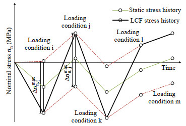 Figure 2 Simulated significant stress history (Dong et al. 2021b)
Whipping and springing increase fatigue loading, especially for large container ships (Corak et al. 2015a; Rajendran and Guedes Soares 2016) and other ships like sea-river ships that are prone to hydroelastic responses despite their shorter length (Wang et al., 2020). For the total stress history (wave frequency stress + high-frequency stress), the fatigue damage is typically determined using the rainflow counting, and the Palmgren-Miner rule referred to as the total damage, while, for wave frequency stress, the fatigue damage is referred to as the wave-induced damage. The difference between the two damages is the vibration damage. From model tests and full-scale measurements, the variation damage was comparable to the wave-induced damage (Storhaug 2014).
Fricke and Paetzold (2014) conducted fatigue tests under variable amplitude loading to investigate the effect of whipping stresses, demonstrating that the rainflow counting and Palmgren-Miner rule are suitable for the total stress history. Still, the damage sum is less than 1 for a measured stress history. It was found that a dominant part of the fatigue damage is caused by the wave frequency stress cycles magnified by whipping if the whipping stress amplitudes are smaller than the wave frequency stress amplitudes. A simplified approach considering only the magnified wave frequency cycles was validated. Some classification societies have established guidelines for engineering practice, e.g. DNVGL (2015a), to assess the effect of whipping and springing on fatigue strength.
The fatigue loading on offshore structures is similar to that on ship structures. The fatigue loading can also be divided into three categories according to their frequency or period. Take offshore pipelines as an example. The offshore pipelines are subjected to several hundred cycles of heat-ups and cool-downs in the service life, which lead to a low number of stress cycles with relative large ranges (Bai and Pan 2017). Additionally, they are affected by wave and current-induced motions of the host facilities and may be subjected to free span Vortex-induced Vibrations (VIVs). The resultant cyclic stresses in pipelines have different frequencies.
In addition to the loads mentioned above, the loads due to the wind fluctuations in terms of speed and direction for offshore wind turbines (Yeter et al. 2015) and the loads due to ice impact (He and Guedes Soares 2021a, b) for iceclass ships or platforms in the Arctic region (Zhang et al. 2011) have achieved great attention and included in the fatigue strength assessment. However, the accidental loads due to collision, and grounding, which can be treated as significant overloads (Liu et al. 2021), are not well associated with fatigue. Overloads or underloads are known to have apparent effects on the fatigue strength of intact or cracked structures. Even though their number of cycles may be very limited in the service life, the stress range is significant. More efforts should also be made to investigate their effects on fatigue strength.
3 Influencing factors
Four influencing factors, i.e., geometry, material, residual stress and environment, are reviewed. It will be shown that the effects of most factors on the fatigue strength of welded joints cannot be neglected, and many studies are devoted to incorporating these effects, i.e., modelling these effects, in the fatigue strength assessment. Some difficulties still exist when explicitly considering these effects in practice.
3.1 Geometry
Fatigue crack initiation and propagation, which most likely occur at the welds rather than in the base metal, are strongly influenced by geometrical weld parameters, including the misalignment, weld toe radius, flank angle, weld throat thickness, undercut and lack of fusion. Some of the parameters are called imperfections (Hobbacher 2015). Since the geometrical parameters can be more easily measured than other factors, extensive studies on their effects were carried out.
3.1.1 Misalignment
Axial and angular misalignments (denoted by e and α, respectively, see Figure 3) are common imperfections for welded ships and offshore structures (Chakarov et al. 2008a, b). The structural stress increases if the misaligned joints are axially loaded due to secondary bending. A Stress Magnification Factor (SMF) can express the stress raising effect, calculated using simple formulas (Hobbacher, 2015).
 Figure 3 Curved deformation shape in thin plate welded joint (Lillemäe et al. 2012)
Recently, the effect of misalignments is particularly of interest when using thin plates in welded ship structures due to their low bending stiffness. Lillemäe et al. (2012) investigated the geometrical properties of the butt welded thin and slender specimens and their effect on the fatigue strength based on fatigue tests and Finite Elements Analysis (FEA). The straightening effect under axial loading was significant and influenced by the slenderness and curved deformation shape near the weld (see Figure 3). To consider the influence of the curved distortion of thin plate butt joints, T joints and cruciform joints, Shen et al. (2021) proposed modified SMF formulas. Zhou et al. (2019) proposed an approach to analytically determine the SMF for angular and buckling distortion modes and global and local angular distortions. Mancini et al. (2020) also derived new analytical formulas to calculate the SMF considering the curved distortion.
Extensive fatigue tests were performed for thin-plate butt welded joints, and T-joints welded using arc, laser and laser-hybrid processes (Fricke et al., 2015). Large misalignments have been observed, particularly for conventionally arc welded joints, resulting in fatigue strength below the S-N curve FAT 80 used in codes based on the nominal stress approach. Based on the structural hot spot stress considering the geometrical non-linearity, almost all the results are above the S-N curve FAT 100 with a slope of m = 3. Dong et al. (2019) assessed the fatigue reliability of butt welded joints with misalignments based on the structural hot spot stress approach. The uncertainties of various influencing factors were considered. The results showed the advantage of laser welding over conventional arc welding in terms of fatigue reliability. The tolerance limits of misalignments specified by standards lead to different reliability levels for different plate thicknesses, and the thin-plate joints show relatively low reliability levels.
The consideration of misalignment in panels is more complicated than those in small-scale specimens, as shown by Fricke and Feltz (2013). The effect of the initial distortion of thin superstructure decks on the ship hull girder bending response and panel loading for fatigue assessment was numerically studied by Lillemäe et al. (2014). It is concluded that the panel-loading for fatigue assessment can be defined from geometrically linear hull girder response analysis without considering the initial distortions. Fatigue tests of thin-plated block joints are carried out by Eggert et al. (2012). The immediate consideration of the stress increase obtained from the geometrically non-linear FEA shows its superiority over applying the simple formulas to calculate the SMF. The reason may be that the simple equations are based on the two-dimensional mechanics of a single plate strip, and the effect of redistribution of membrane stresses is not considered.
Lillemäe et al. (2013) investigated the structural behaviour of different levels of panel structures, from plate strips to actual panels using the FEA. High non-linear behaviour of the plate strip model and relatively linear behaviour of actual plate and panel models were shown in typical fatigue relevant ranges. For panels, the shape of the initial distortion and the magnitude of the initial distortion significantly affect the maximum structural stresses. However, the straightening effect is not as significant for actual panels as for small-scale specimens. A geometrically non-linear FEA with accurately measured panel shape is necessary to calculate the structural response to consider the actual deformation shape.
The fatigue test results of small- and full-scale specimens were analysed in terms of structural hot spot stress by Lillemäe et al. (2017a). The results showed that when initial distortion shape and geometrical non-linearity are appropriately considered, the small- and full-scale specimens have equal fatigue strength with small scatter and the same S-N curve slope close to m = 5. This slope was also reported by Sonsino et al. (2010). A benchmark study on welding-induced distortion in structural stress analysis of thin-plate welded structures was carried out by Lillemäe et al. (2017b). The modelling approach to estimating the structural hot spot stress and the critical fatigue location along the butt weld was compared and discussed.
The Stress Intensity Factors (SIFs) of surface cracks in misaligned plate-to-plate butt welded joints were evaluated by Zhao et al. (2017) using the FEA. It was found that the solutions based on the SMF and the SIF solutions of Newman and Raju (1986) underestimate the SIF for shallow cracks. The underestimation was attributed to the SMF being the hot spot Stress Concentration Factor (SCF) rather than the actual SCF. The use of the notch SCF can significantly overestimate the SIF. The SIF of misaligned joints can also be calculated using the weight function method (Shen and Glinka 1991), as shown by Dong and Guedes Soares (2019), where the local notch stress distribution and global membrane and bending stress distribution were considered.
Misalignment can also occur in girth welds of offshore pipelines and risers. The girth welds are more critical than those in other ships and offshore structures because there is no redundancy, and failure of one weld means failure of the whole system. The formulas of SMF for various misalignment scenarios can be found in the work of Lotsberg (2016). Similar to misalignments, dents in pipelines are also a significant factor influencing the fatigue strength uncer cyclic loading (Pinheiro et al., 2019).
3.1.2 Weld geometry
It has been shown that the weld geometry parameters significantly affect the fatigue strength of welded joints. The effects were investigated experimentally and numerically. For non-load-carrying fillet welded cruciform joints, Lee et al. (2009) performed fatigue tests on various weld geometry configurations. It was observed that the fatigue life gradually increases with increasing the weld flank angle and weld toe radius, and the weld throat thickness itself has little influence on the fatigue life (the three parameters are represented by θ, ρ and a in Figure 4, respectively).
 Figure 4 Weld geometry parameters in a fillet welded cruciform joint (weld toe radius ρ, flank angle θ, slit length l, weld leg length h, weld penetration depth p, weld throat thickness a)
Barsoum and Jonsson (2011) investigated the fatigue strength of seam welds fabricated with different weld positions. The weld position significantly affects the weld quality, i. e., the weld toe radius and the fatigue resistance of fillet welds. The effect of arc weld toe geometry on fatigue performance was studied by Shiozaki et al. (2018) using aswelded and toe machined welded joints of ultra-high-strength steel. Weld toe machining significantly improved the fatigue strength of the welded joints even when the radius of the machined toe was 0.5 mm (as-welded toe radius most likely in the range of 0.2-0.3 mm). According to fatigue life simulation results for butt welded joints presented by Schork et al. (2018), the weld geometry effects become more significant toward the endurance limits, and the effects of weld toe radius and flank angle are more important than those of the excess weld metal height within the range simulated.
The above studies focus on the weld toe geometries because the fatigue cracks normally originate from the weld toe for the considered welded joints. However, the weld root fatigue is also a significant failure mode, especially for fillet welds or single-sided welds (Fricke, 2013). For T-butt welded joints with partial penetration, the fatigue strength was significantly decreased with the increase in the lack of penetration (Beretta et al. 2009). The failure mode of single-sided girth welds in offshore pipelines and risers is typically the weld root fatigue (Horn et al. 2018). The fatigue failure locations of full-scale girth welded pipes under fatigue loading were often characterised by relatively poor weld root bead profiles (Zhang and Maddox, 2014).
Since the weld geometry affects the fatigue strength or failure mode of welded joints, modelling the effects is essential for an accurate fatigue strength assessment. However, it depends on the assessment approach being applied. Some approaches require a detailed weld geometry as input, while others only rely on rough information or ignore the information of the weld geometry. The crack propagation approach, notch stress approach, notch strain approach, Notch Stress Intensity Factor (NSIF) approach etc., can consider the local weld geometry effect in estimating structural responses.
The weld toe radius and flank angle significantly influence the local stress distribution and SIF (Mikulski and Lassen 2019; Tsang et al. 2018), evaluated using the FEA. In practice, the effect of the weld toe radius on the SIF solutions is roughly considered (Bowness and Lee 2000). Dong and Guedes Soares (2019) reported an approach based on the weight function method to calculate the SIF of semielliptical surface cracks originating from the notch of welded joints. The stress distribution along the potential crack plane required in the weight function method was constructed based on the NSIF approach in the highly stressed zone and the equivalent linearised stress distribution. The approach can predict the SIF solutions for various weld toe radii and sharp notches with singular stress distribution.
A web-frame corner specimen's fatigue crack initiation location was successfully identified from several hot spots using the effective notch stress approach based on measured weld shapes instead of the idealized isosceles-right-triangle shape (Fricke et al. 2012). The effect of weld shape on the notch stress factor (effective notch stress divided by the nominal stress) of the weld toe and root in load-carrying cruciform joints (Dong et al. 2021c). It was found that an approximately linear relationship exists between the notch stress factor and position variations of the shape control points (four dots as shown in Figure 4(b)). The sensitive factor that represents the effect of the position variation of one control point on the notch stress factor is shown in Figure 5. It can be seen that the weld penetration and weld leg length are the most significant parameters influencing the fatigue strength of the considered load-carrying cruciform joint. The linear relationship between the weld penetration and the notch stress factor for T-butt welded joints with partial penetration was illustrated by Beretta et al. (2009).
 Figure 5 Effect of position variations of weld shape control points on the notch stress factor (Dong et al. 2021c)
The weld geometry that can transfer the failure mode from weld root fatigue to weld toe fatigue is of interest because the weld root fatigue is more dangerous and should be avoided in engineering practice. For load-carrying cruciform joints, the transition weld geometry depends on the plate thickness, slit length, and weld leg length (the definition of these parameters is shown in Figure 4) (Maddox 1974). Dong and Guedes Soares (2015a) determined the transition weld geometry based on Neuber's stress averaging approach. Xing et al. (2016) proposed two types of fillet weld sizing criteria based on effective traction stress and equivalent effective traction stress. The effect of misalignment was then further included in the analyses (Xing et al. 2017). Song et al. (2017) used the NSIF, and Strain Energy Density (SED) approaches to predict load-carrying cruciform joints' fatigue failure mode transition with various sizes.
3.1.3 Other imperfections
The geometrical parameters discussed in the last two subsections represent macro geometry features. Combining the macro and micro geometry features dominates the fatigue crack initiation and early propagation behaviour. In weld class systems (Barsoum and Jonsson 2011, Jonsson et al. 2011, Jonsson et al. 2016), where the weld quality and the fatigue strength are related, the types of imperfections that are closely related to fatigue strength are weld toe geometry, misalignment, undercut, cold laps, inclusions, porosity, crack and crack imperfections.
For welded joints, the fatigue crack is likely initiated from the locations where there is a combination of unfavourable weld geometry that results in a high stress concentration zone and the presence of the initial defects in the zone (Mikulski and Lassen 2019). In an early experimental study (Otegui et al. 1989), the initiation sites were observed to be undercuts, slag inclusions, and surface spatters at the weld toe surface. A combined experimental and numerical study on the welded specimens with actual weld geometry was performed by Hou (2007). It indicated that the significant cracks do not necessarily initiate from the location with the highest SCF but from the location of weld toe plastic stripes. The crack initiation sites and early propagation were experimentally investigated by Schork et al. (2018). It was found that the crack initiation sites are not related to the weld toe radius and flank angle, but are controlled by a combination of surface roughness features and weld ripple edges, which cause additional stress concentration.
The fatigue behaviour of welded joints is significantly affected by the microgeometry features. Alam et al. (2010) showed that the crack initiation location can be shifted from the toe to the weld bead when the toe radius is large, and the surface ripples determine the main stress raiser location for cracking. The undercuts were considered one reason for the large fatigue strength scatter for thin plate welded plates (Remes and Fricke 2014). Measurements on laser-hybrid welded butt joints performed by Liinalampi et al. (2016) showed that small undercut-type imperfections exist both in the toe and root side, acting as stress risers. The study investigated the influence of the actual weld geometry on the fatigue strength using the measured microscale weld geometry and notch stress approach (Neuber's stress averaging approach). The large scatter in fatigue strength within the nominal, and structural stress approach was reduced using a notch stress approach with a significantly short averaging length.
The term "secondary notch" was used by Schork et al. (2018) to describe an additional notch in the region of the weld toe, which is regarded as the primary notch (see Figure 6). A secondary notch can be an undercut, a measure of the surface roughness (the maximum depth of the surface topography near the weld toe), or stress raising geometry feature at the edge of a weld ripple. The roughness based secondary notch was measured. It was shown that the secondary notch depth has a significant effect on the simulated fatigue strength of butt welded joints. The secondary notch effect was modelled within the notch strain approach by Dong et al. (2021b), which was significant in fatigue reliability.
 Figure 6 Secondary notch located at the weld toe of a butt welded joint (Schork et al. 2018)
The most common feature of all the geometrical parameters for welded joints is their variation. The variation occurs along the weld toe of individual joints and from joint to joint. The geometrical parameters depend on the welding conditions and manufacturing process. Even using the same welding technique, the welding current, voltage, travel speed, work angle and welding position may vary during the welding process, resulting in some variation in the geometrical parameters.
The statistics of the weld toe radius and flank angle from various studies were summarised by Schork et al. (2018). The geometrical parameters used to determine the statistical distribution were generally measured from different sections along the weld line. The wide variability of the data sets was shown due to different joint types, welding processes, and plate and weld thicknesses under consideration. Due to the variation of the weld geometry, the uncertainty of the SCF and notch stress factor were demonstrated and investigated (Hou 2007; Liinalampi et al. 2016). This may be the primary reason for the scatter in the fatigue strength of welded joints.
The difference between the automatic and manual welds should be noted. In an early study, the automated welding technique resulted in less variation of the weld geometry along the weld line. Still, the minimum weld toe radii for the two processes are comparable (Otegui et al. 1989). The growth and coalescence of surface micro-cracks at the toes of automatic welds are accelerated due to a straighter and sharper weld toe than the manual welds. Limited investigations on the fatigue behaviour of new automatic welds are available. Some efforts should be made since automated welding techniques are increasingly used in shipyards.
One crucial issue that should be addressed is how to choose representative values of geometrical parameters in fatigue strength analyses of welded joints in cases with significant uncertainties. Three options were identified by Zerbst et al. (2014):
• The worst-case assumptions
• Introducing the geometrical parameters as statistical inputs
• The upper or lower limits of weld quality criteria
When estimating the local structural responses, the worstcase assumption is employed in most fatigue strength assessment approaches. It implies that fatigue cracks are initiated from the location with the worst weld geometry, e.g. zero weld toe radius. However, as mentioned above, the crack initiation sites are controlled by many factors and the weld geometry. Besides, the worst weld geometry is unrealistic, e. g. the weld toe radius typically has a value larger than zero.
The geometrical parameters can be treated as random variables in probabilistic fatigue analyses (Dong et al. 2018c, 2019; Dong et al. 2021b; Madia et al. 2018). It is normally challenging to obtain the statistical descriptors of these random variables. The weld quality criteria can be reasonable inputs for fatigue analyses (Schork et al. 2018). The international weld quality standard ISO 5817 (ISO 2014) and the Volvo standard STD 181-0004 (VOLVO 2008) contain such criteria for various geometrical parameters corresponding to specific fatigue strength. The probabilistic models of some geometrical parameters were assumed by Dong et al. (2021b), based on the weld quality criteria, regarded as characteristic values corresponding to the probability level of 5% or 95%.
3.2 Material
The material of the areas where fatigue cracks are initiated and propagated is also an important influencing factor. This is especially true if the fatigue process occurs at relatively mild notches. The fatigue strength increases with the tensile strength of the material. However, the effect of tensile strength on fatigue strength is negligible for steel structures with relatively sharp notches, e.g. welds, in the High Cycle Fatigue (HCF) regime (Maddox 1991). Therefore, steel welds' S-N curves and fatigue crack propagation rate curves in fatigue design codes can be employed for a wide range of materials with yield stress less than a relatively high value, e.g. 960 MPa. The reason for the insensitivity of the fatigue strength of welded joints to the material may be that the fatigue crack propagation life dominates the total fatigue life of welded joints with sharp notches. It is well-known that the crack propagation behaviour in the Paris regime is only slightly affected by the microstructures within whole material classes such as steels (Kucharczyk et al. 2018).
With the progress of the welding technology, the fatigue crack initiation life, which is strongly related to material properties, is also significant. The view that the material effect on the fatigue strength of welded joints is negligible is changing. In a detailed fatigue life estimation of typical welded joints based on the fracture mechanics, the material properties of the crack initiation site, the Heat Affected Zone (HAZ), rather than those of the Base Metal (BM), lead to a good approximation of the experimental fatigue lives (Madia et al. 2018).
The weld has a complex material configuration, containing the BM, HAZ and Weld Metal (WM), as shown in Figure 7. The HAZ can be further divided into various material zones with different microstructures and mechanical properties because they experience different thermal cycles (Kucharczyk et al. 2018). The fatigue cracks are normally initiated from the HAZ for weld toe fatigue and the WM for weld root fatigue. The HAZ or WM material properties control the crack initiation and early propagation. However, the material properties of BM were still used in some studies. One reason may be that the use of the material properties of BM normally results in conservative fatigue life predictions (Dong et al. 2017; Radaj et al. 1998).
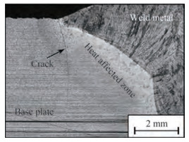 Figure 7 Fatigue crack initiation and propagation in the HAZ in a butt-welded joint (Schork et al. 2018)
Another reason lies in the difficulty in determining the material properties of HAZ since the width of the HAZ is normally in the order of millimetres. The specimens with homogeneous microstructures cannot be directly extracted. Two options to determine the material properties of the HAZ exist, one is the reproduction of HAZ microstructures by simulating the actual thermal cycles on BM specimens, and another is the estimation based on the parameters that are easy to be measured, e.g. the hardness and the correlation between various material properties (Kucharczyk et al. 2018). The latter is more practical but relies on the accuracy of the empirical equation describing the correlation. There are some studies devoted to developing these equations based on a large number of experimental data (Lopez and Fatemi 2012; Roessle and Fatemi 2000).
The fatigue behaviour of welds with inhomogeneous material is also of interest. The availability of material properties of different zones makes it possible to model the welded joints with various zones in the FEA. Remes (2008) analysed the stress or strain response around the notch of a laser-welded joint using the non-linear FEA. The effect of material inhomogeneity was considered by dividing the model into different material zones. Comparing inhomogeneous material models with homogeneous material models (with the HAZ material), it was concluded that inhomogeneity is of minor importance in the initial and cyclic loading with applied nominal stress levels below the yield limit of the BM. The material property of the weld notch in the HAZ was applied to the whole fusion zone, and the BM material property was used elsewhere to model the possible yielding of the base plate (Remes 2013).
The usage of an inhomogeneous material model and notch strain approach results in a good fatigue life prediction of the spot and friction stir spot welded joints, according to Wang and Shang (2009). The effect of material inhomogeneity on fatigue strength of an annealed butt welded joint was analysed by Dong et al. (2017) using the non-linear FEA and notch strain approach. The material properties of different zones were estimated using empirical equations based on the measured hardness. The notch stresses and strains and fatigue lives estimated from the inhomogeneous and homogeneous models under different loading conditions were compared. Compared with the results of inhomogeneous models, the homogeneous models with the HAZ material result in either lower notch strain amplitudes or lower mean stresses and slightly non-conservative life estimations.
Welding causes a mismatch in strength between the BM and WM. Overmatch joints in which the yield strength of the WM is higher than that of the BM are usually required to shield the WM from plastic deformation. According to the LCF and HCF tests on the load-carrying cruciform joints with various strength matching conditions, the effect of strength matching was shown to be obvious in the LCF region while negligible in the HCF region (Saiprasertkit et al. 2012b). The specimens with a lower mismatch ratio (ratio of the yield stresses of the WM and the BM) show lower fatigue strength. The weld geometry and the strength mismatched influenced the fatigue crack initiation site and propagation path (Saiprasertkit et al. 2014; Song et al. 2021). According to numerical analyses carried out by Dong et al. (2017), with the increase in the mismatch ratio, the crack initiation life was extended until it approached a certain level.
3.3 Residual stresses
Residual stresses also have a significant impact on the fatigue life of welded joints (Radaj et al. 2006). The weldinginduced residual stresses, which may be tensile and approach the material's yield stress, can increase the mean stress of the local stress-strain cycles, reducing the fatigue strength. Besides, some post-weld treatment processes can introduce favourable weld geometry and compressive residual stresses, improving fatigue strength (Yuan and Sumi 2016). The residual stress effect is generally considered using S-N curves or fatigue crack growth rate curves determined in relatively high-stress ratios in current fatigue design codes. The effect of residual stresses cannot be accurately quantified. Therefore, many efforts have been made to investigate and model the effect.
To reasonably account for the residual stress effect, accurate knowledge of residual stresses embedded in welded joints is a prerequisite. Welding-induced residual stresses are mainly caused by differential thermal expansion and shrinkage of the WM and BM. During the cooling process, the shrinkage of the heated material is hindered by cooler adjacent material, resulting in non-uniform tensile residual stresses along the weld. Another mechanism of inducing residual stresses is that the phase transformation of the welded material leads to a volume expansion, which is suppressed by adjacent material, causing compressive residual stresses. This process is presently modelled by finite elements (Chen et al. 2018), producing adequate results for several applications, such as the ultimate strength of stiffened panels (Chen and Guedes Soares 2018). The weldinginduced residual stresses can often be classified into two types, the near-weld self-equilibrating residual stresses and the residual stresses due to structural restraint, as introduced by Hensel et al. (2018). More detailed information on two types of residual stresses could be useful for fatigue assessment. However, separating the two types of residual stresses is often difficult in practice.
The determination of the residual stress distribution in welds is challenging. Compared with the laborious and costly experimental methods, the numerical methods are more flexible and can obtain the results of the whole welded structure in question. However, it requires extensive and accurate input to provide reliable results. Since it is difficult to have sufficient details of the inputs, and the results are sensitive to these inputs, results usually are not satisfactory. Manai et al. (2020) collected a large amount of measured residual stress data to study its distribution at the weld toe and through the thickness of the welded plate. Probabilistic analyses of the data show considerable uncertainties in the distribution.
Due to the difficulty in the residual stress determination and the considerable uncertainty of the obtained residual stress, many safety assessment procedures, e. g. BS 7910 (BSI 2013), provide representative residual stress profiles of welded joints, with reliable residual stress information being not available. These profiles represent the upper bounds of measured or simulated residual stresses, leading to an underestimated fatigue life. It has been found that butt-welded plates made from different steel grades show high tensile residual stresses in the weld centreline but relatively low residual stresses in the area of the weld toes (Farajian 2013). It is not consistent with the common assumption that the residual stresses around the weld toe are relatively high and may approach the material's yield stress. The reason was that former investigations ignored the effects of austenitic phase transformation (Hensel et al. 2018). Relatively low residual stresses at the weld toe were also reported by Manai et al. (2020). The mean value of some experimental data is 0.35 yield stress of the material. High residual stresses approaching the material's yield stress were measured at the weld toe of large-scale specimens with high restraint or self-restraint specimens, e. g. plate with longitudinal stiffener (Farajian 2013; Hensel et al. 2018).
The initial residual stress field induced by the manufacturing process may not remain stable during the service life. The relaxation and re-distribution of the initial residual stresses under cyclic loading should be considered in an accurate estimation of the fatigue performance of welded joints. A literature review on this topic can be found (Hensel et al. 2018; McClung 2007). Many studies have reported significant relaxation and re-distribution of residual stresses on the first loading cycle, followed by slight relaxation on subsequent cycles. The first cycle behaviour is triggered if the summation of the local residual stresses and local stresses caused by external loading is higher than the monotonic yield strength. The further variations become relevant if the material shows cyclic softening (Hensel et al. 2018).
The relaxation and re-distribution behaviour is complex, depending on initial residual stress condition, external loading, local notch condition, material properties, et al. According to a comparison of the fatigue strength between the as-welded and stress-relieved welded joints (Ferro 2014), the residual stress effect on fatigue strength of welded joints is more significant for low applied stress ranges. In contrast, the effect is negligible for high applied stress ranges. This phenomenon is because the residual stress relaxation and re-distribution due to local plasticity are expected for high applied stress ranges. The residual stress effect on the crack initiation life was reported by Lawrence et al. (1981) in the frame of the notch strain approach, where the relaxation of residual stresses at the weld toe due to the first cycle and subsequent cycles were considered. The residual stress relaxation due to the first cycle was considered by Dong et al. (2018b) using the FEA. The fatigue crack initiation life estimations using the notch strain approach agree with experimental results. Note that these studies were carried out under constant amplitude loadings rather than the more realistic variable amplitude loadings.
Sonsino (2009) reviewed the residual stress effect on the fatigue strength of welded joints, which depends on the loading mode, spectrum shape, and weld geometry, among others. In the study, some comparisons of the fatigue strength between the as-welded and stress-relieved welded joints were performed under spectrum loading and constant amplitude loading. The results are similar to those in Ferro (2014), as shown in Figure 8. There is some difference in the stress decreasing effect of tensile residual stresses between the spectrum loading and constant amplitude loading.
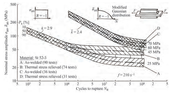 Figure 8 Fatigue life curves of as-welded and stress-relieved longitudinal stiffener under constant and variable amplitude loading (Sonsino 2009)
The residual stress effect on the fatigue crack propagation is also investigated in many studies (McClung 2007). There usually are two approaches to consider the effect: the superposition approach and the crack closure approach. The superposition approach uses an effective R ratio that incorporates the residual stress-induced SIF, which can be determined using the weight function method or the FEA (Bao et al. 2010). The crack closure approach relies on the crack closure concept, assuming that the residual stress field influences the crack opening stress. Neutron diffraction has been used to measure the evolution of residual stress in VPPA welded aluminium specimens as a fatigue crack is grown under a constant SIF range (Liljedahl et al. 2008). Finite element simulations of the evolution of residual stress were also performed using the elastic model and elastic-plastic model. It has been shown that the evolution is governed by elastic re-distribution, but the plasticity caused by fatigue loading plays a role. The experimental results also indicate no crack closure in the specimen. Liljedahl et al. (2009) used the two approaches to model the effect of the residual stresses on the fatigue crack behaviour in welded aluminium plate specimens. A good correlation between the experimental results and the predictions were found for the crack closure approach at a high SIF range.
In contrast, the superposition approach yielded good predictions at low and moderate SIF ranges. The discrepancy was attributed to the significant residual stress relaxation caused by gross plastic effects at high SIF ranges and the difficulty in the crack opening stress determination at low SIF ranges. In a similar study (Liljedahl et al. 2010), the evolution of the residual stresses in a MIG-welded aluminium specimen was shown to be governed by elastic redistribution at constant amplitude loading, and the superposition approach can be used successfully in the assessment of the fatigue behaviour if the initial residual stress field in the component is known.
3.4 Environment
Ships and offshore structures may be operated in areas with seasonal freezing temperatures and extreme environmental conditions. However, studies on the fatigue strength of welded joints at sub-zero temperatures are scarce.
The fatigue strength of welded specimens made from AH36 and DH32 steel grades under room and cold temperature conditions was experimentally investigated by Bridges et al. (2012). The test steel specimens' mean fatigue strength at low temperature was slightly higher than that at room temperature. Therefore, the fatigue strength assessment procedure recommended by Lloyd's Register (Zhang et al. 2011) did not change the fatigue design curves. Zhao et al. (2020) performed fatigue crack propagation tests and hardness tests on the welded joint and BM of DH36 steel at room temperature and −60 ℃. Decreasing the temperature can reduce the fatigue crack propagation rate and improve the hardness value. The fatigue strength of fillet welded loadcarrying and non-load-carrying cruciform joints of a normal and high strength steel were experimentally investigated at room −20 ℃ and −50 ℃ (Braun et al. 2020b). An increase in the fatigue strength for low temperatures was also shown in the fatigue test results. Braun et al. (2020a) investigated the applicability of local fatigue assessment methods to welded joints exposed to sub-zero temperatures. Wang et al. (2021) conducted a series of fatigue tests on T welded joint and BM of EH36 steel at room temperature and −40 ℃ and showed that the fatigue life at low temperature is not shorter than that at room temperature.
4 Fatigue strength assessment
Various fatigue strength assessment approaches for welded joints exist. It can generally be divided into the S-N curve approaches based on the Palmgren-Miner rule, and the fatigue crack propagation approach relying on the fracture mechanics (Chen et al. 2011). The former is more suitable for use in the design stage, while the latter is attractive within the frame of the damage tolerance philosophy and can be used for inspection and maintenance planning. Section 4.1 mainly introduces studies on various S-N curve approaches. Some applications of these approaches are also reviewed. Section 4.2 mainly focuses on various research topics of the fatigue crack propagation approach.
4.1 S-N curve approach
There exist many S-N curve approaches. The main difference among the various approaches is the S parameter being used, e.g. the nominal stress, hot spot stress, effective notch stress, strain energy density, notch strain, etc. The nominal stresses are calculated using the beam theory or FEA with coarse meshes and include macro-geometric effects, concentrated load effects and misalignment effects. Different design S-N curves are assigned according to the weld joint types.
There are many cases where the nominal stress cannot be clearly defined due to the complex geometric effect. The hot spot stress approach is usually used in these cases. The difference between the nominal and hot spot stress definitions is that the hot spot stresses are uniquely defined along the weld toe. The hot spot stress covers all stress raising effects induced by the structural details, excluding the stress concentrations due to the weld itself. To eliminate the non-linear peak stress caused by the notch, the hot spot stress is obtained by extrapolating surface stresses at reference points to the weld toe or linearising the stress through plate thickness. The surface stress extrapolation methods can be found in some codes (DNVGL 2015b; Hobbacher 2015). The thickness linearisation methods to determine the hot spot stress were reported based on a special shell element FEA (Chattopadhyay et al. 2011) and a 3D coarse meshed FEA (Goyal et al. 2016).
The structural stress approach proposed by Dong (2001) and Dong et al. (2010) has gained increasing popularity. An equivalent structural stress range parameter was proposed, including the structural stress calculated using a special procedure (Dong 2005), a dimensionless parameter derived from fracture mechanics considerations, crack propagation exponent and plate thickness. The validity of the structural stress definition and calculation procedures have been proven by its ability to effectively consolidate a large amount of published weld fatigue S–N data from various industries into a narrow band. Although the approach is classified as a structural stress approach, the notch effect of the weld toe and the fatigue crack propagation analysis are involved in the formulation of the approach, leading to a relatively good performance in fatigue strength assessment of welded joints.
The effective notch stress approach assumes that the averaged notch stress in a small volume at the notch root controls the fatigue strength of welded joints. It can be simulated by the maximum stress of a corresponding notch with an enlarged fictitious radius. The background and assessment procedures of the effective notch stress approach are well documented (Fricke 2012; Radaj et al. 2006; Sonsino et al. 2012). The approach has been successfully applied in many weld toe and root fatigue cases and included in IIW recommendations (Hobbacher 2015). Fricke et al. (2012) performed the small- and full-scale fatigue tests for web frame corners and the intersection between longitudinals and transverse web frames in ship structures to validate some widely used approaches for fatigue strength assessment. It has been shown that the effective notch stress approach allows the consideration of the weld shape, which could partly explain differences in the observed and calculated failure behaviour, and the applicability of the different approaches is quite good if some specific aspects are observed.
The effective notch stress approach has deficiencies in a high T-stress at the weld slit tip (weld root as shown in Figure 4) under silt parallel loading, which leads to overrated notch stress at the slit tip (Radaj et al. 2009). The T-stress is the stress parallel to the slit. It may explain why the failure mode of lap joints and cover plates (weld root or toe fatigue) was not well identified by the effective notch stress approach (Dong and Guedes Soares 2015a; Fricke and Feltz 2010). Dong and Guedes Soares (2015a) showed that there exists compressive T-stress at the weld root of load-carrying cruciform joints, leading to tensile stress at the keyhole if the effective notch stress approach is used. The notch stress can also be overrated. The ambiguity of weld root keyhole positioning and cross-sectional weakening is also problematical (Radaj et al. 2009). In the fatigue assessment of the sandwich plate, a down-ward shifted keyhole with minimum interrupt of stress flow in the loading plate results in non-conservative fatigue lives (Fricke et al. 2009). These deficiencies are due to the existence of a keyhole placed at the weld root.
The nominal stress, hot spot stress and effective notch stress approaches were widely used in the fatigue damage assessment of ship and offshore structures. Guedes Soares et al. (2003) evaluated the fatigue life of ship structures based on a local stress approach combined with a probabilistic approach that considers the stochastic nature of the ocean environmental loading and the service profile of the ship. Garbatov et al. (2005a) performed the fatigue damage assessment of a welded joint of a fast ferry's car deck for trucks with very high tensile steel trapezoidal stiffeners subjected to still water wave and slamming induced loadings as well as truck induced load effects. Different welding connections between trapezoid longitudinals and the deck plate of the fast ferry were examined based on the hot spot stress approach (Garbatov et al. 2010). A complete stochastic spectral fatigue analysis of a newly built FPSO planned to operate for a 25-year service life was presented by Garbatov et al. (2005b). Fatigue damage assessment of double hull oil tanker structural details was performed by Nguyen et al. (2012), based on global and local structural finite element models. The wave-induced vertical and horizontal bending moments and local pressure loads were accounted for, and local stress analyses were considered based on the notch stress approach. Time-dependent stresses as a function of corrosion deterioration were analyzed based on nonlinear corrosion wastage during the design life of the ship. A spectral fatigue damage analysis of a double hull tanker structural detail was carried out by Nguyen et al. (2013), accounting for corrosion wastage over time. Yeter et al. (2015) performed a spectral fatigue damage assessment of a fixed offshore wind turbine supporting structure, which integrates modern sea, wind, soil interaction, finite element and fatigue analyses in the frequency domain. Different wideband solutions of fatigue damage were compared (Yeter et al. 2016).
Extensive studies on the NSIF were carried out by Lazzarin et al. (1998, 2001, 2003). The NSIF controls the stress field in the vicinity of the notch tip. Thus, the fatigue life of the welded joints was expected to be governed by the cyclic NSIF, and NSIF–N curves were established. Because of the inconsistency of units of the different opening angle NSIF values, the NSIFs corresponding to different opening angle V-notches cannot be compared directly. Consequently, the local SED averaged over a control volume surrounding the notch tip was proposed to characterise notched components' static and fatigue behaviour, as shown in Figure 9 (Berto and Lazzarin 2009 2014; Lazzarin et al. 2014). The calculation of the local SED of notches in welded joints can be accurately estimated using coarse meshes in the FEA (Lazzarin et al. 2010). The local SED concept was successfully applied to analyse various fatigue problems of welded joints (Berto et al. 2016; Berto et al. 2017; Song et al. 2017).
 Figure 9 Fatigue strength of welded joints as a function of the averaged local strain energy density (Berto and Lazzarin 2009)
An alternative approach based on the NSIF is the peak stress method (PSM) proposed by Meneghetti and Lazzarin (2007). It is an engineering, FEA-oriented method that rapidly estimates the NSIF using linear elastic FEA with coarse meshes. Some developments of the PSM can be found in recent studies (Meneghetti et al. 2015; Meneghetti et al. 2016; Meneghetti et al. 2018; Meneghetti and Campagnolo, 2020).
To assess the LCF strength of welded structures, a structural strain approach (pseudo hot spot stress approach) consistent with the conventional hot spot stress was recommended in the fatigue design code of ship structures (DNVGL 2015b). The mesh-insensitive structural stress proposed by Dong (2001) was also extended to the LCF regime, and a structural strain method was presented by Dong et al. (2014). The structural strain definition is consistent with the classical plate and shell theory in which a linear through-thickness deformation field exists in both elastic and elastic-plastic regimes. Considering both yield and equilibrium conditions, the structural strains can be solved. The method was shown to be effective in correlating LCF test data into a single narrow band consistent with the scatter band of the existing mater S-N curve. Pei and Dong (2019) proposed an analytical method to determine the structural strain considering the material strain hardening effect and the plane strain state. An equivalent structural strain range parameter was introduced to evaluate fatigue behaviours of welded components spanning both LCF and HCF regimes (Pei et al. 2019).
The notch strain approach was developed based on the idea that the fatigue life to crack initiation at the notch tip is the same as the total fatigue life in an unnotched comparison specimen if the stress-strain states are the same. The primary step of the approach is the notch stress and strain estimation. For welded joints, the notch radius is substantially smaller than the weld line length, implying that a plane strain state (biaxial stress state) may dominate around the notch (Dowling 2013). Dong and Guedes Soares (2017) evaluated five estimation methods used in the plane strain state and took results from elastic-plastic FEA as a reference. It has been shown that the equivalent strain energy density approach for the plane strain state (Glinka 1985) works well for the studied cases. The well-known strain-life curve (Basquin-Coffin-Manson relationship) was also rewritten for the plane strain state. The authors used the approach in some applications and showed good performance(Dong et al. 2018a, b). Note that there are also some exceptions where the fatigue cracks are initiated from the edge of the welded specimen, implying a plane stress state (uniaxial stress state) (Dong et al. 2017). A constraint factor proposed by Sharp (1992) may quantify the stress state condition.
In addition to the stress state problem, another problem associated with the notch strain approach is the unclear definition of the crack initiation at the notch tip. The output of the notch strain approach is the fatigue crack initiation life, but the size of the initiated crack is ambiguous. In previous studies, the size of the initiated crack was usually defined in the range from 0.1 mm to 1 mm (Dong et al. 2018a). To deal with the problem, a strain-life curve corresponding to a crack size was formulated by Dong et al. (2018a) based on the equivalence between the Coffin-Manson law and a simple Elastic-Plastic Fracture Mechanics crack growth law in the LCF regime. Therefore, the strainlife curve can obtain the fatigue life to a specific crack size at the notch tip.
Even though the notch strain approach can consider the effect of weld geometry, material and residual stress, the difficulty in its practical application remains. Radaj et al. (1998) investigated the applicability of the notch strain approach in evaluating the fatigue strength of a K-shaped tubular joint. The notch strain approach resulted in unacceptably significant differences in the predicted fatigue life under similarly acceptable assumptions concerning the material state, local hardness and residual stresses. The combination of the real weld geometry obtained by 3D laser scanning and the notch strain approach was investigated by Ladinek et al. (2018). It has been shown that depending on the combination of various mean stress models, plasticity correction methods and material data, the predicted fatigue lifetimes vary from unrealistic to pretty accurate. Different modelling options can lead to significantly different results.
The effective notch strain approach partially overcomes the notch strain approach's limitations in practical applications. The approach no longer requires residual stresses and actual weld geometry information. Based on the effective notch concept, where a fictitious notch is introduced at the weld root and toe, the effective notch strain was determined at the crack initiation points of load-carrying cruciform joints with a material mismatching and incomplete penetration using the elastic-plastic FEA (Hanji et al. 2011; Saiprasertkit et al. 2012b). The radius of the fictitious notch is 1 mm. A unique relationship between the effective notch strain range and fatigue life was obtained. The fatigue life was defined as the number of cycles when the maximum load is dropped by 20% due to crack propagation. It includes a substantial crack propagation life in addition to the crack initiation life.
An effective strain estimation method was developed for the weld root based on the nominal strain for load-carrying cruciform joints (Saiprasertkit et al. 2012a). The effective notch strain approach was successfully applied to identify load-carrying cruciform joints' fatigue crack initiation points (Saiprasertkit et al. 2014). Fricke et al. (2014) and Corigliano et al. (2018) analysed the LCF strength of welded joints in ship structures, demonstrating the applicability of the effective notch strain approach. Dong et al. (2015b, 2021c) used the equivalent strain energy density approach in the plane strain state (Glinka 1985) and the elastic effective notch stress to estimate the effective notch strain at the weld toe or root, and the estimating procedures were validated using some experimental data in LCF regime, as shown in Figure 10. Combining with the effective notch stress in the HCF regime recommended by IIW (Hobbacher 2015), a universal approach was formulated to deal with LCF and HCF problems.
 Figure 10 Effective notch strain range vs fatigue life curve in LCF and HCF regime (Dong et al. 2021c)
4.2 Fatigue crack propagation approach
The fatigue crack propagation approach for fatigue strength assessment of welded joints has become attractive since the proposal of the damage tolerance philosophy. The idea is that flaws will inevitably exist in welded structures, and the fatigue crack propagation approach based on fracture mechanics is used to assess the significance of flaws (Maddox 1974). After years of development, the approach has become more sophisticated and is included in some codes (BSI 2013; Hobbacher 2015).
One challenging problem of using the fatigue crack propagation approach for welded joints is determining the initial crack size. It has been shown that the fatigue life predictions are strongly affected by the initial crack size. There are some ways to assess the initial crack size: the weld defect size, the Non-destructive Inspection (NDI) limit, the back-extrapolation method etc. Some metallographic and fractographic investigations on the defect size in welded joints were summarised by Madia et al. (2018). Once there is no identification of defects when performing NDI, the NDI limit can be used as the initial crack size, leading to unrealistic short fatigue life estimations. The latter uses fatigue crack growth analysis for long cracks, i.e., the Linear Elastic Fracture Mechanics (LEFM) can be employed, with an assumed initial crack geometry and size to match the S-N curve, and the initial crack size is obtained by trial and error (Liu and Mahadevan 2009). The initial crack size of 0.1 mm recommended by IIW is obtained from the back-extrapolation method (Hobbacher 2015). Note that cracks around 0.1 mm cannot be considered long cracks (Dong et al. 2018a). When materials do not show significant defects, an approach based on a so-called cyclic R-curve analysis was proposed to determine the initial crack size (Zerbst and Madia 2015). The initial crack size can be defined when the non-propagating condition of a semi-circular crack in a plate in tension at a stress level equal to the endurance limit of the material is considered.
Accurate SIFs for typical cracks in welded joints are required in the assessment. In addition to the straightforward numerical methods, the empirical equations are normally used to determine the SIFs. For a general case where a semi-elliptical surface crack is located at the weld toe of welded plate structures, one option is the combination of the three-dimensional weld toe magnification factor developed by Bowness and Lee (2000) and the SIFs for plain plate surface cracks developed by Newman and Raju (1981). Some new weld toe magnification factors for the butt joint, T-butt joint with double side weld, and non-load-carrying cruciform joint were developed by Lie et al. (2015, 2017). The option may fail to predict the SIF at the surface points of the welded T-butt joints with semi-elliptical cracks (Dong and Guedes Soares, 2019; Schiaretti et al. 2021). Another option of empirical equations for SIF determination is presented in Baik et al. (2011). In the study, fatigue tests on various types of specimens under cyclic bending load were carried out. The experimental results were compared with the fatigue crack propagation behaviour predictions based on the empirical equations. Peng et al. (2017) further improved the equations by updating the correction factors. Xiao et al. (2012) illustrated that the empirical SIF equations of Newman and Raju (1981) can give a better fatigue life evaluation of transverse fillet welded joints in bending than the other alternatives.
The SIFs of cracks in pipelines are also of interest. Hoh et al. (2016) developed the SIF and weld toe magnification factor solutions for semi-elliptical surface cracks in a circumferentially welded pipe. Based on the Newman and Raju equations (Newman and Raju 1981), Li et al. (2020) proposed new bending correction factors and geometry correction factors to determine the SIFs for internal and external circumferential surface cracks in plain pipes subjected to bending.
The weight function method is flexible and accurate to estimate the SIFs due to residual stresses and external loading. The SIFs are calculated by integrating the product of weight function and stress distribution in the potential crack plane. The weight function for various cracks has been developed, e.g. the one for semi-elliptical surface cracks in a finite thickness plate (Shen and Glinka 1991). Only the stress distribution at the potential crack plane is required in practice. Goyal and Glinka (2013) successfully estimated the fatigue lives of welded joints by considering the fatigue process as a fatigue crack growth from an initial intrinsic crack size (the initial crack size was also employed by the UniGrow model, which will be introduced later). The weight function method was used to determine the SIFs, and the stress distribution was determined using the FEA at the potential crack plane, i.e., the section of the weld toe and weld throat of load-carrying cruciform joints, see Figure 11.
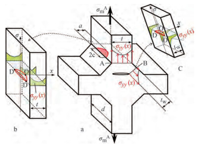 Figure 11 Load-carrying cruciform joint with the crack model for the weld toe and weld throat section (Goyal and Glinka, 2013)
The weight function method was also used by Dong and Guedes Soares (2019) to determine the SIFs, and, consequently, estimate the fatigue crack growth behaviour from an initial semi-circular surface crack of 0.1 mm located at the weld toe of welded joint specimens. The stress distribution in the potential crack plane was calculated based on the NSIF. The stress singularity at the sharp weld toe was considered, leading to overestimated SIFs for the surface point of surface cracks. The overestimation can compensate for the effect caused by neglecting multiple crack initiation and coalescence in the modelling. The predicted fatigue lives were in good agreement with experimental results.
The Paris law is still the most convincing model to describe the fatigue crack growth rate in engineering practice. Some of the studies mentioned above used the simple Paris law or its variants. However, the simple Paris law cannot explain some fatigue crack growth behaviour. Some more advanced fatigue crack growth models were developed.
For example, Huang et al. (2007, 2008) proposed an engineering Fatigue Crack Growth Rate (FCGR) model that can consider the R-ratio effect and the load interaction effect. Using an equivalent SIF range, the model can condense the FCGR data under different R-ratios to the single curve of R = 0. The crack growth retardation caused by overload and the effect of an underload that follows an overload i.e., reduced crack growth retardation effect were included by correcting the equivalent SIF range. Based on the Mcevily model, Cui et al. (2014) developed a unified fatigue life prediction model to consider various experimental phenomena. A two-parameter model for FCGR based on the elastic-plastic crack tip stress-strain history was proposed by Noroozi et al. (2005, 2007). The residual stresses induced by cyclic plasticity near the crack tip have been considered to affect the crack growth, and thus the crack closure was not involved. The two-parameter model was modified to account for variable amplitude loading effects, resulting in the UniGrow model. The model can also predict the fatigue lives of notched and welded components where both the crack initiation and propagation are essential (Mikheevskiy et al. 2015).
To consider more general conditions where the LEFM is no longer applicable, the FCGR models based on the ElasticPlastic Fracture Mechanics (EPFM) are developed. Instead of the SIF, the strain intensity factor was considered the crack driving force (Kamaya 2015). The Crack Tip Opening Displacement (CTOD) correlated with the FCGR. The FCGR model can describe the evolution of micro-cracks under pure LCF and combined LCF and HCF loading conditions (Schweizer et al. 2011). Extended from the monotonic J-integral, the cyclic J-integral has attracted significant attention. An effective cyclic J-integral was applied in many studies to consider the crack closure effect (Eufinger et al. 2013; Ngoula et al. 2017). The plastic part of the cyclic J-integral was demonstrated to be the parameter governing the short crack growth rate in large-scale yielding conditions (Hutař et al. 2017). The FCGR data from various materials were condensed into a unique curve.
Many FCGR models use the crack closure concept to model various effects. However, the crack closure concept is under debate, especially in-plane strain conditions (Pippan and Hohenwarter 2017). Some experimental results do not support the physical crack closure (Croft et al. 2005; Liljedahl et al. 2010). Unlike the structures with relatively thin plates in some other industries, the ships and offshore structures use relatively thick plates. The surface cracks and through-thickness cracks in thick plates are more relevant in ships and offshore structures, implying that the plane strain state dominates if the crack size is relatively small (Yue et al. 2018). The approaches and conclusions resulting from thin plate cracked specimens may need further verification.
The fatigue crack propagation in ship structures was investigated in many studies. Garbatov et al. (2004) analysed the fatigue crack growth of knuckle detail typical of tankers using Paris law based on an experimentally determined geometry correction function. A practical application of the fracture mechanics approach to the fatigue assessment of main deck longitudinals of an oil tanker was presented by Parunov et al. (2013). The analyses considered the stress increase due to the corrosion degradation of the midship section modulus. The fatigue crack propagation in bulb stiffeners, which are widely used in ships, was investigated by Yue et al. (2017) using experimental and numerical methods. An experimental and numerical assessment of crack growth in a welded stiffened panel was performed by Feng et al. (2021). The relationship of the crack propagation rate between the stiffened panel plate and the web was analysed.
There are also two-phase approaches and continuum approaches to model the fatigue processes at the welded joints. The two-phase approach calculates the fatigue crack initiation and propagation life separately, while the continuum approaches consider the fatigue process continuous. The initial crack size required in the fatigue crack propagation approach is no longer needed. The reason for developing these approaches is based on the argument that the fatigue crack initiation and propagation life are both significant in some cases, especially for high-quality welds. The crack initiation life usually dominates in relatively smooth specimens with few defects under low-stress ranges.
Chattopadhyay et al. (2011) determined the structural stress of welded joints using a special shell finite element analysis technique, and relevant SCFs were subsequently used to determine the peak stress and the non-linear throughthickness stress distributions. The peak stress at the weld toe was subsequently used to assess fatigue crack initiation life to a crack size of 0.5-0.8 mm based on the notch strain approach. The stress distribution and the weight function method were used to determine SIFs and analyse the fatigue crack growth. Mikulski and Lassen (2019) divided the two phases by the crack depth of 0.1 mm. It was found that the crack initiation phase is close to 25% of the fatigue life of non-loading-carrying cruciform joins, even at a relatively high-stress range of 150 MPa. A general model that combines the two phases without defining a priori the transition size was proposed by Navarro et al. (2011, 2014) to estimate life in notches and fretting fatigue. Each phase was analysed independently, and the transition size is considered a parameter to be obtained during the process.
Dong et al. (2018a) formulated a strain-life curve corresponding to the transition crack size where the two phases are divided to estimate the crack initiation life. A crack growth model that includes the short crack behaviour was used to predict the crack propagation life. The transition crack size associated with the average grain size of the material was chosen, considering the stress gradient and microstructure effects. Remes et al. (2012) and Remes (2013) developed a continuum approach that enables the fatigue crack growth simulation from the crack initiation to the critical crack length of welded joints. The material characteristic length defined from grain size statistics was continuously damaged according to cumulative damage models.
5 Conclusions
Fatigue is a significant failure mode that has to be considered in ships and offshore structures during design, manufacturing, and operation. The first step in avoiding fatigue failure is investigating the fatigue loading acting on structures. Even though the fatigue design codes have established the representative fatigue loading, it simplifies the realistic one. Investigation and improvement in fatigue loading are still necessary, especially for different marine structures from those accustomed.
Many factors related to welding processes have a significant impact on fatigue strength. Detailed investigation of their effects can improve the understanding of the fatigue mechanism, leading to more accurate models of these effects. Besides, the representative values of these factors need more investigation.
Different approaches for the fatigue analysis of welded joints are available. They are developed under different simplification, assumptions and constraints and have various limitations. Extension and improvement of existing approaches and development of new approaches are still needed.
Nomenclature
BM Base metal CTOD Crack tip opening displacement e Axial misalignment EPFM Elastic-plastic fracture mechanics FCGR Fatigue crack growth rate FEA Finite elements analysis HAZ Heat affected zone LEFM Linear elastic fracture mechanics LCF Low cycle fatigue NDI Non-destructive inspection NSIF Notch stress intensity factor PSM Peak stress method SCF Stress concentration factor SED Strain energy density SIF Stress intensity factor SMF Stress magnification factor VIV Vortex-induced vibration WM Weld metal α Angular misalignment Open Access This article is licensed under a Creative Commons Attribution 4.0 International License, which permits use, sharing, adaptation, distribution and reproduction in any medium or format, as long as you give appropriate credit to the original author(s) and thesource, provide a link to the Creative Commons licence, and indicateif changes were made. The images or other third party material in thisarticle are included in the article’s Creative Commons licence, unlessindicated otherwise in a credit line to the material. If material is notincluded in the article’s Creative Commons licence and your intendeduse is not permitted by statutory regulation or exceeds the permitteduse, you will need to obtain permission directly from the copyrightholder. To view a copy of this licence, visit http://creativecommons.org/licenses/by/4.0/. -
Figure 1 LCF loading for ship structures (Dong et al. 2021b)
Figure 2 Simulated significant stress history (Dong et al. 2021b)
Figure 3 Curved deformation shape in thin plate welded joint (Lillemäe et al. 2012)
Figure 4 Weld geometry parameters in a fillet welded cruciform joint (weld toe radius ρ, flank angle θ, slit length l, weld leg length h, weld penetration depth p, weld throat thickness a)
Figure 5 Effect of position variations of weld shape control points on the notch stress factor (Dong et al. 2021c)
Figure 6 Secondary notch located at the weld toe of a butt welded joint (Schork et al. 2018)
Figure 7 Fatigue crack initiation and propagation in the HAZ in a butt-welded joint (Schork et al. 2018)
Figure 8 Fatigue life curves of as-welded and stress-relieved longitudinal stiffener under constant and variable amplitude loading (Sonsino 2009)
Figure 9 Fatigue strength of welded joints as a function of the averaged local strain energy density (Berto and Lazzarin 2009)
Figure 10 Effective notch strain range vs fatigue life curve in LCF and HCF regime (Dong et al. 2021c)
Figure 11 Load-carrying cruciform joint with the crack model for the weld toe and weld throat section (Goyal and Glinka, 2013)
BM Base metal CTOD Crack tip opening displacement e Axial misalignment EPFM Elastic-plastic fracture mechanics FCGR Fatigue crack growth rate FEA Finite elements analysis HAZ Heat affected zone LEFM Linear elastic fracture mechanics LCF Low cycle fatigue NDI Non-destructive inspection NSIF Notch stress intensity factor PSM Peak stress method SCF Stress concentration factor SED Strain energy density SIF Stress intensity factor SMF Stress magnification factor VIV Vortex-induced vibration WM Weld metal α Angular misalignment -
Alam M, Barsoum Z, Jonsén P, Kaplan A, Häggblad H-Å (2010) The influence of surface geometry and topography on the fatigue cracking behaviour of laser hybrid welded eccentric fillet joints. Applied Surface Science 256(6): 1936-1945. https://doi.org/10.1016/j.apsusc.2009.10.041 Bai Q, Pan J (2017) Pipeline Fatigue and Fracture Design. Encyclopedia of Maritime and Offshore Engineering 1-18. https://doi.org/10.1002/9781118476406.emoe561 Baik B, Yamada K, Ishikawa T (2011) Fatigue crack propagation analysis for welded joint subjected to bending. International Journal of Fatigue 33(5): 746-758. https://doi.org/10.1016/j.ijfatigue.2010.12.002 Bao R, Zhang X, Yahaya NA (2010) Evaluating stress intensity factors due to weld residual stresses by the weight function and finite element methods. Engineering Fracture Mechanics 77(13): 2550-2566. https://doi.org/10.1016/j.engfracmech.2010.06.002 Barsoum Z, Jonsson B (2011) Influence of weld quality on the fatigue strength in seam welds. Engineering Failure Analysis 18(3): 971-979. https://doi.org/10.1016/j.engfailanal.2010.12.001 Beretta S, Bernasconi A, Carboni M (2009) Fatigue assessment of root failures in HSLA steel welded joints: A comparison among local approaches. International Journal of Fatigue 31(1): 102-110. https://doi.org/10.1016/j.ijfatigue.2008.05.027 Berto F, Lazzarin P (2009) A review of the volume-based strain energy density approach applied to V-notches and welded structures. Theoretical and Applied Fracture Mechanics 52(3): 183-194. https://doi.org/10.1016/j.tafmec.2009.10.001 Berto F, Lazzarin P (2014) Recent developments in brittle and quasibrittle failure assessment of engineering materials by means of local approaches. Materials Science and Engineering: R: Reports 75: 1-48. https://doi.org/10.1016/j.mser.2013.11.001 Berto F, Campagnolo A, Chebat F, Cincera M, Santini M (2016) Fatigue strength of steel rollers with failure occurring at the weld root based on the local strain energy values: modelling and fatigue assessment. International Journal of Fatigue 82: 643-657. https://doi.org/10.1016/j.ijfatigue.2015.09.023 Berto F, Vinogradov A, Filippi S (2017) Application of the strain energy density approach in comparing different design solutions for improving the fatigue strength of load carrying shear welded joints. International Journal of Fatigue 101: 371-384. https://doi.org/10.1016/j.ijfatigue.2016.09.001 BMA (2004) Report of the investigation into the loss of the Bahamian registered tanker 'Prestige' off the northwest coast of Spain on 19th November 2002. The Bahamas MaritimeAuthority. Bowness D, Lee M (2000) Prediction of weld toe magnification factors for semi-elliptical cracks in T-butt joints. International Journal of Fatigue 22(5): 369-387. https://doi.org/10.1016/S0142-1123(00) 00012-8 https://doi.org/10.1016/S0142-1123(00)00012-8 Braun M, Milaković A-S, Renken F, Fricke W, Ehlers S (2020a) Application of local approaches to the assessment of fatigue test results obtained for welded joints at sub-zero temperatures. International Journal of Fatigue 138: 105672. https://doi.org/10.1016/j.ijfatigue.2020.105672 Braun M, Scheffer R, Fricke W, Ehlers S (2020b) Fatigue strength of fillet-welded joints at subzero temperatures. Fatigue & Fracture of Engineering Materials & Structures 43(2): 403-416. https://doi.org/10.1111/ffe.13163 Bridges R, Zhang S, Shaposhnikov V (2012) Experimental investigation on the effect of low temperatures on the fatigue strength of welded steel joints. Ships and Offshore Structures 7(3): 311-319. https://doi.org/10.1080/17445302.2011.563550 BS 7910 (2013) Guide to methods for assessing the acceptability of flaws in metallic structures. British Standards Institution. Chakarov K, Garbatov Y, Guedes Soares C (2008a) Fatigue analysis of ship deck structure accounting for imperfections. International Journal of Fatigue 30(10): 1881-1897. https://doi.org/10.1016/j.ijfatigue.2008.01.015 Chakarov K, Garbatov Y, Guedes Soares C (2008b) Hot spot stress and stress concentration factors due to different fabrication imperfections in deck structures. International Shipbuilding Progress 55(1-2): 47-62. https://doi.org/10.3233/ISP-2008-0038 Chattopadhyay A, Glinka G, El-Zein M, Qian J, Formas R (2011) Stress analysis and fatigue of welded structures. Welding in the World 7(55): 2-21. https://doi.org/10.1007/BF03321303 Chen B-Q, Guedes Soares C (2018) A simplified model for the effect of weld-induced residual stresses on the axial ultimate strength of stiffened plates. Journal of Marine Science and Application 17(1): 57-67. https://doi.org/10.1007/s11804-018-0007-7 Chen B-Q, Hashemzadeh M, Garbatov Y, Guedes Soares C (2018) Recent Developments in Experimental and Numerical Assessments of Welding-Induced Residual Stresses. International Conference on Offshore Mechanics and Arctic Engineering (OMAE), Madrid. (ASME paper OMAE2018-77652) https://doi.org/10.1115/OMAE2018-77652 Chen N-Z, Wang G, Guedes Soares C (2011) Palmgren-Miner's rule and fracture mechanics-based inspection planning. Engineering Fracture Mechanics 78(18): 3166-3182. https://doi.org/10.1016/j.engfracmech.2011.08.002 Corak M, Parunov J, Guedes Soares C (2015a) Probabilistic load combination factors of wave and whipping bending moments. Journal of Ship Research 59(1): 11-30. https://doi.org/10.5957/JOSR.59.1.140052 Corak M, Parunov J, Guedes Soares C (2015b) Long-term prediction of combined wave and whipping bending moments of containership. Ship & Offshore Structures 10(1): 4-19. https://doi.org/10.1080/17445302.2013.833022 Corigliano P, Crupi V, Dong P, Fricke W, Guglielmino E (2018) Local Strain Approaches for LCF Life Prediction of Ship Welded Joints. Technology and Science for the Ships of the Future: Proceedings of NAV 2018: 19th International Conference on Ship & Maritime Research 166-175. https://doi.org/10.3233/978-1-61499-870-9-166 Croft M, Zhong Z, Jisrawi N, Zakharchenko I, Holtz R, Skaritka J, Fast T, Sadananda K, Lakshmipathy M, Tsakalakos T (2005) Strain profiling of fatigue crack overload effects using energy dispersive X-ray diffraction. International Journal of Fatigue 27(10-12): 1408-1419. https://doi.org/10.1016/j.ijfatigue.2005.06.022 Cui W, Huang X, Wang F (2014) Towards a unified fatigue life prediction method for marine structures. Springer. https://doi.org/10.1115/OMAE2010-21007 DNVGL-CG-0153 (2015a) Fatigue and ultimate strength assessment of container ships including whipping and springing. Hovik: Det Norske Veritas. DNVGL-CG-0129 (2015b) Fatigue Assessment of Ship Structures. Hovik: Det Norske Veritas. Dong P (2001) Astructural stress definition and numerical implementation for fatigue analysis of welded joints. International Journal of Fatigue 23(10): 865-876. https://doi.org/10.1016/S0142-1123(01) 00055-X https://doi.org/10.1016/S0142-1123(01)00055-X Dong P (2005) A robust structural stress method for fatigue analysis of offshore/marine structures. Journal of Offshore Mechanics and Arctic Engineering 127(1): 68-74. https://doi.org/10.1115/1.1854698 Dong P, Hong JK, Osage DA, Dewees DJ, Prager M (2010) The Master S-N Curve Method: An Implementation for Fatigue Evaluation of Welded Components in the ASME B & PV Code, Section Ⅷ, Div 2 and API 579-1/ASME FFS-1. Welding Research Council Bulletin. Dong P, Pei X, Xing S, Kim M (2014) A structural strain method for low-cycle fatigue evaluation of welded components. International Journal of Pressure Vessels and Piping 119: 39-51. https://doi.org/10.1016/j.ijpvp.2014.03.003 Dong Y, Guedes Soares C (2015a) On the fatigue crack initiation point of load-carrying fillet welded joints. in: Towards Green Marine Technology and Transport, Guedes Soares C, Dejhalla R, Pavletic D, (Eds.), Taylor & Francis Group, 407-416. https://doi.org/10.1201/b18855-53 Dong Y, Guedes Soares C (2015b) Estimation of effective notch strain for fatigue strength assessment of welded structures under multiaxial stress state. in: Towards Green Marine Technology and Transport, Guedes Soares C, Dejhalla R, Pavletic D, (Eds.), Taylor & Francis Group, 397-406. https://doi.org/10.1201/b18855-52 Dong Y, Garbatov Y, Guedes Soares C (2017) Fatigue strength assessment of an annealed butt welded joint accounting for material inhomogeneity. in: Progress in the Analysis and Design of Marine Structures, Guedes Soares C, Garbatov Y, (Eds.), Taylor & Francis Group, 349-359. https://doi.org/10.1201/9781315157368-40 Dong Y, Guedes Soares C (2017) Uncertainty analysis of local strain and fatigue crack initiation life of welded joints under plane strain condition. in: Progress in the Analysis and Design of Marine Structures, Guedes Soares C, Garbatov Y, (Eds.), Taylor & Francis Group, 337-347. https://doi.org/10.1201/9781315157368-41 Dong Y, Garbatov Y, Guedes Soares C (2018a) A two-phase approach to estimate fatigue crack initiation and propagation lives of notched structural components. International Journal of Fatigue 116: 523-534. https://doi.org/10.1016/j.ijfatigue.2018.06.049 Dong Y, Garbatov Y, Guedes Soares C (2018b) Fatigue crack initiation assessment of welded joints accounting for residual stress. Fatigue & Fracture of Engineering Materials & Structures 41(8): 1823-1837. https://doi.org/10.1111/ffe.12824 Dong Y, Teixeira AP, Guedes Soares C (2018c) Time-variant fatigue reliability assessment of welded joints based on the PHI2 and response surface methods. Reliability Engineering & System Safety 177: 120-130. https://doi.org/10.1016/j.ress.2018.05.005 Dong Y, Guedes Soares C (2019) Stress distribution and fatigue crack propagation analyses in welded joints. Fatigue & Fracture of Engineering Materials & Structures 42(1): 69-83. https://doi.org/10.1111/ffe.12871 Dong Y, Teixeira AP, Guedes Soares C (2019) Fatigue reliability analysis of butt welded joints with misalignments based on hotspot stress approach. Marine Structures 65: 215-228. https://doi.org/10.1016/j.marstruc.2019.01.006 Dong Y, Garbatov Y, Guedes Soares C (2021a) Fatigue strength assessment of a butt-welded joint in ship structures based on time-domain strain approach. Journal of Ship Research 65(2): 123-138. https://doi.org/10.5957/JOSR.04180019 Dong Y, Garbatov Y, Guedes Soares C (2021b) Strain-based fatigue reliability assessment of welded joints in ship structures. Marine Structures 75: 102878. https://doi.org/10.1016/j.marstruc.2020.102878 Dong Y, Garbatov Y, Guedes Soares C (2021c) Improved effective notch strain approach for fatigue reliability assessment of loadcarrying fillet welded cruciform joints in low and high cycle fatigue. Marine Structures 75: 102849. https://doi.org/10.1016/j.marstruc.2020.102849 Dowling NE (2013) Mechanical behavior of materials: engineering methods for deformation, fracture, and fatigue. Pearson. https://doi.org/10.1016/S0142-1123(96) 00087-4 https://doi.org/10.1016/S0142-1123(96)00087-4 Eggert L, Fricke W, Paetzold H (2012) Fatigue strength of thinplated block joints with typical shipbuilding imperfections. Welding in the World 56(11-12): 119-128. https://doi.org/10.1007/BF03321402 Eufinger J, Heinrietz A, Bruder T, Hanselka H (2013) An engineering approach to fatigue analysis based on elastic-plastic fracture mechanics. Fatigue & Fracture of Engineering Materials & Structures 36(1): 65-74. DOI: 10.1111/j.1460-2695.2012.01680.x Farajian M (2013) Welding residual stress behavior under mechanical loading. Welding in the World 57(2): 157-169. https://doi.org/10.1007/s40194-013-0024-8 Feng G, Wang Y, Garbatov Y, Ren H, Guedes Soares C (2021) Experimental and numerical analysis of crack growth in stiffened panels. Ships and Offshore Structures 16(9): 980-992. https://doi.org/10.1080/17445302.2020.1790297 Ferro P (2014) The local strain energy density approach applied to pre-stressed components subjected to cyclic load. Fatigue & Fracture of Engineering Materials & Structures 37(11): 1268-1280. https://doi.org/10.1111/ffe.12211 France E (2019) The Alexander L. Kielland disaster revisited: A review by an experienced welding engineer of the catastrophic north sea platform collapse. Journal of Failure Analysis and Prevention 19(4): 875-881. Fricke W, Paetzold H, Zipfel B (2009) Fatigue tests and numerical analyses of a connection of steel sandwich plates. Welding in the World 53(7): R151-R157. https://doi.org/10.1007/BF03266726 Fricke W, Feltz MO (2010) Fatigue tests and numerical analyses of partial-load and full-load carrying fillet welds at cover plates and lap joints. Welding in the World 54(7-8): R225-R233. https://doi.org/10.1007/BF03263508 Fricke W (2012) IIW recommendations for the fatigue assessment of welded structures by notch stress analysis: IIW-2006-09. Woodhead Publishing. DOI: 10.1533/9780857098566 Fricke W, von Lilienfeld-Toal A, Paetzold H (2012) Fatigue strength investigations of welded details of stiffened plate structures in steel ships. International Journal of Fatigue 34(1): 17-26. https://doi.org/10.1016/j.ijfatigue.2011.01.021 Fricke W (2013) IIW guideline for the assessment of weld root fatigue. Welding in the World 57(6): 753-791. DOI: 10.1007/s40194-013-0066-y Fricke W, Feltz O (2013) Consideration of influence factors between small-scale specimens and large components on the fatigue strength of thin-plated block joints in shipbuilding. Fatigue & Fracture of Engineering Materials & Structures 36(12): 1223-1231. https://doi.org/10.1111/ffe.12058 Fricke W, Friedrich N, Musumeci L, Paetzold H (2014) Low-cycle fatigue analysis of a web frame corner in ship structures. Welding in the World 58(3): 319-327. https://doi.org/10.1007/s40194-014-0117-z Fricke W, Paetzold H (2014) Effect of whipping stresses on the fatigue damage of ship structures. Welding in the World 58(2): 261-268. https://doi.org/10.1007/s40194-014-0111-5 Fricke W, Remes H, Feltz O, Lillemäe I, Tchuindjang D, Reinert T, Nevierov A, Sichermann W, Brinkmann M, Kontkanen T (2015) Fatigue strength of laser-welded thin-plate ship structures based on nominal and structural hot-spot stress approach. Ships and Offshore Structures 10(1): 39-44. https://doi.org/10.1080/17445302.2013.850208 Fricke W (2017) Fatigue and fracture of ship structures. in: Encyclopedia of Maritime and Offshore Engineering, (Eds.), Wiley. https://doi.org/10.1002/9781118476406.emoe007 Garbatov Y, Rudan S, Guedes Soares C (2004) Assessment of geometry correction functions of tanker knuckle details based on fatigue tests and finite-element analysis. Journal of Offshore Mechanics Arctic Engineering 126(3): 220-226. https://doi.org/10.1115/1.1782643 Garbatov Y, Santos J, Guedes Soares C (2005a) Effect of truck induced load on welded structural joints subjected to fatigue. in: Maritime transportation and exploitation of ocean and coastal resources, Guedes Soares C, Garbatov Y, Fonseca N, (Eds.), Taylor & Francis Group, London, UK, 413-422. https://doi.org/10.1201/9781439833728.ch49 Garbatov Y, Tomasevic S, Guedes Soares C (2005b) Fatigue damage assessment of a newly built FPSO hull. in: Maritime transportation and exploitation of ocean and coastal resources, Guedes Soares C, Garbatov Y, Fonseca N, (Eds.), Taylor & Francis Group, London, UK, 423-428. https://doi.org/10.1201/9781439833728.ch50 Garbatov Y, Rudan S, Guedes Soares C (2010) Fatigue assessment of welded trapezoidal joints of a very fast ferry subjected to combined load. Engineering Structures, 32(3), 800-807. https://doi.org/10.1016/j.engstruct.2009.12.007 Glinka G (1985) Energy density approach to calculation of inelastic strain-stress near notches and cracks. Engineering Fracture Mechanics 22(3): 485-508. https://doi.org/10.1016/0013-7944(85) 90148-1 https://doi.org/10.1016/0013-7944(85)90148-1 Goyal R, Glinka G (2013) Fracture mechanics-based estimation of fatigue lives of welded joints. Welding in the World 57(5): 625-634. https://doi.org/10.1016/j.engfailanal.2018.07.017 Goyal R, El-Zein M, Glinka G (2016) A robust stress analysis method for fatigue life prediction of welded structures. Welding in the World 2(60): 299-314. DOI: 10.1007/s40194-016-0295-y Guedes Soares C (1990) Stochastic Models of Load Effects for the Primary Ship Structure. Structural Safety 8(1-4): 353-368. https://doi.org/10.1016/0167-4730(90) 90052-Q https://doi.org/10.1016/0167-4730(90)90052-Q Guedes Soares C, Moan T (1988). Statistical analysis of stillwater load effects in ship structures. Transaction of the Society of Naval Architects and Marine Engineers 96(4): 129-156. Guedes Soares C, Moan T (1991) Model Uncertainty in the Long Term Distribution of Wave Induced Bending Moments for Fatigue Design of Ship Structures. Marine Structures. 4295-315. https://doi.org/10.1016/0951-8339(91) 90008-Y https://doi.org/10.1016/0951-8339(91)90008-Y Guedes Soares C, Garbatov Y, Von Selle H (2003) Fatigue damage assessment of ship structures based on the long-term distribution of local stresses. International Shipbuilding Progress 50(1, 2): 35-55. Hanji T, Saiprasertkit K, Miki C (2011) Low-and high-cycle fatigue behavior of load-carrying cruciform joints with incomplete penetration and strength under-match. International Journal of Steel Structures 11(4): 409-425. https://doi.org/10.1007/s13296-011-4002-y He X, Guedes Soares C (2021a) Experimental study on the dynamic behavior of beams under repeated impacts. International Journal of Impact Engineering 147: 103724. https://doi.org/10.1016/j.ijimpeng.2020.103724 He X, Guedes Soares C (2021b) Numerical study on the pseudoshakedown of beams under repeated impacts. Ocean Engineering 242: 110137. https://doi.org/10.1016/j.oceaneng.2021.110137 Hensel J, Nitschke-Pagel T, Tchoffo Ngoula D, Beier H-T, Tchuindjang D, Zerbst U (2018) Welding residual stresses as needed for the prediction of fatigue crack propagation and fatigue strength. Engineering Fracture Mechanics 198: 123-141. https://doi.org/10.1016/j.engfracmech.2017.10.024 Hobbacher A (2015) Recommendations for fatigue design of welded joints and components. Springer. https://doi.org/10.1007/978-3-319-23757-2 Hoh HJ, Pang JHL, Tsang KS (2016) Stress intensity factors for fatigue analysis of weld toe cracks in a girth-welded pipe. International Journal of Fatigue 87: 279-287. https://doi.org/10.1016/j.ijfatigue.2016.02.002 Horn AM, Lotsberg I, Orjaseater O (2018) The rationale for update of SN curves for single sided girth welds for risers and pipelines in DNV GL RP C-203 based on fatigue performance of more than 1700 full scale fatigue test results. International Conference on Ocean, Offshore and Arctic Engineering (OMAE), Madrid. (ASME paper OMAE2018-78408) https://doi.org/10.1115/OMAE2018-78408 Hou C-Y (2007) Fatigue analysis of welded joints with the aid of real three-dimensional weld toe geometry. International Journal of Fatigue 29(4): 772-785. https://doi.org/10.1016/j.ijfatigue.2006.06.007 Huang X, Moan T (2007) Improved modeling of the effect of R-ratio on crack growth rate. International Journal of Fatigue 29(4): 591-602. https://doi.org/10.1016/j.ijfatigue.2006.07.014 Huang X, Torgeir M, Cui W (2008) An engineering model of fatigue crack growth under variable amplitude loading. International Journal of Fatigue 30(1): 2-10. https://doi.org/10.1016/j.ijfatigue.2007.03.004 Hutař P, Poduška J, Šmíd M, Kuběna I, Chlupová A, Náhlík L, Polák J, Kruml T (2017) Short fatigue crack behaviour under low cycle fatigue regime. International Journal of Fatigue 103: 207-215. https://doi.org/10.1016/j.ijfatigue.2017.06.002 ISO 5817 (2014) Welding-Fusion-welded joints in steel, nickel, titanium and their alloys (beam welding excluded)-Quality levels for imperfections. Jonsson B, Samuelsson J, Marquis GB (2011) Development of weld quality criteria based on fatigue performance. Welding in the World 55(11-12): 79-88. https://doi.org/10.1007/BF03321545 Jonsson B, Dobmann G, Hobbacher A, Kassner M, Marquis G (2016) IIW guidelines on weld quality in relationship to fatigue strength. Springer. https://doi.org/10.1007/978-3-319-19198-0 Kamaya M (2015) Low-cycle fatigue crack growth prediction by strain intensity factor. International Journal of Fatigue 72: 80-89. https://doi.org/10.1016/j.ijfatigue.2014.11.002 Kucharczyk P, Madia M, Zerbst U, Schork B, Gerwien P, Münstermann S (2018) Fracture-mechanics based prediction of the fatigue strength of weldments. Material aspects. Engineering Fracture Mechanics 198: 79-102. https://doi.org/10.1016/j.engfracmech.2017.09.010 Ladinek M, Niederwanger A, Lang R, Schmid J, Timmers R, Lener G (2018) The strain-life approach applied to welded joints: Considering the real weld geometry. Journal of Constructional Steel Research 148: 180-188. https://doi.org/10.1016/j.jcsr.2018.04.024 Lawrence F, Ho N, Mazumdar PK (1981) Predicting the fatigue resistance of welds. Annual Review of Materials Science 11(1): 401-425. https://doi.org/10.1146/annurev.ms.11.080181.002153 Lazzarin P, Tovo R (1998) A notch intensity factor approach to the stress analysis of welds. Fatigue & Fracture of Engineering Materials & Structures 21(9): 1089-1103. https://doi.org/10.1046/j.1460-2695.1998.00097.x Lazzarin P, Livieri P (2001) Notch stress intensity factors and fatigue strength of aluminium and steel welded joints. International Journal of Fatigue 23(3): 225-232. https://doi.org/10.1016/S0142-1123(00) 00086-4 https://doi.org/10.1016/S0142-1123(00)00086-4 Lazzarin P, Lassen T, Livieri P (2003) A notch stress intensity approach applied to fatigue life predictions of welded joints with different local toe geometry. Fatigue & Fracture of Engineering Materials & Structures 26(1): 49-58. https://doi.org/10.1046/j.1460-2695.2003.00586.x Lazzarin P, Berto F, Zappalorto M (2010) Rapid calculations of notch stress intensity factors based on averaged strain energy density from coarse meshes: Theoretical bases and applications. International Journal of Fatigue 32(10): 1559-1567. https://doi.org/10.1016/j.ijfatigue.2010.02.017 Lazzarin P, Campagnolo A, Berto F (2014) A comparison among some recent energy-and stress-based criteria for the fracture assessment of sharp V-notched components under Mode I loading. Theoretical and Applied Fracture Mechanics 71: 21-30. https://doi.org/10.1016/j.tafmec.2014.03.001 Lee CH, Chang KH, Jang GC, Lee CY (2009) Effect of weld geometry on the fatigue life of non-load-carrying fillet welded cruciform joints. Engineering Failure Analysis 16(3): 849-855. https://doi.org/10.1016/j.engfailanal.2008.07.004 Li Z, Jiang X, Hopman H, Zhu L, Liu Z (2020) An investigation on the circumferential surface crack growth in steel pipes subjected to fatigue bending. Theoretical and Applied Fracture Mechanics 105: 102403. https://doi.org/10.1016/j.tafmec.2019.102403 Lie S, Vipin S, Li T (2015) New weld toe magnification factors for semi-elliptical cracks in double-sided T-butt joints and cruciform X-joints. International Journal of Fatigue 80: 178-191. https://doi.org/10.1016/j.ijfatigue.2015.05.016 Lie S, Zhao H, Vipin S (2017) New weld toe magnification factors for semi-elliptical cracks in plate-to-plate butt-welded joints. Fatigue & Fracture of Engineering Materials & Structures 40(2): 207-220. DOI: 10.1111/ffe.12485 Liinalampi S, Remes H, Lehto P, Lillemäe I, Romanoff J, Porter D (2016) Fatigue strength analysis of laser-hybrid welds in thin plate considering weld geometry in microscale. International Journal of Fatigue 87: 143-152. DOI: 10.1016/j.ijfatigue.2016.01.019 Liljedahl C, Tan M, Zanellato O, Ganguly S, Fitzpatrick M, Edwards L (2008) Evolution of residual stresses with fatigue loading and subsequent crack growth in a welded aluminium alloy middle tension specimen. Engineering Fracture Mechanics 75(13): 3881-3894. https://doi.org/10.1016/j.engfracmech.2008.02.005 Liljedahl C, Brouard J, Zanellato O, Lin J, Tan M, Ganguly S, Irving PE, Fitzpatrick M, Zhang X, Edwards L (2009) Weld residual stress effects on fatigue crack growth behaviour of aluminium alloy 2024-T351. International Journal of Fatigue 31(6): 1081-1088. https://doi.org/10.1016/j.ijfatigue.2008.05.008 Liljedahl C, Zanellato O, Fitzpatrick M, Lin J, Edwards L (2010) The effect of weld residual stresses and their re-distribution with crack growth during fatigue under constant amplitude loading. International Journal of Fatigue 32(4): 735-743. https://doi.org/10.1016/j.ijfatigue.2009.10.012 Lillemäe I, Lammi H, Molter L, Remes H (2012) Fatigue strength of welded butt joints in thin and slender specimens. International Journal of Fatigue 44: 98-106. https://doi.org/10.1016/j.ijfatigue.2012.05.009 Lillemäe I, Remes H, Romanoff J (2013) Influence of initial distortion on the structural stress in 3mm thick stiffened panels. Thin-Walled Structures 72: 121-127. DOI: 10.1016/j.tws.2013.07.001 Lillemäe I, Remes H, Romanoff J (2014) Influence of initial distortion of 3 mm thin superstructure decks on hull girder response for fatigue assessment. Marine Structures 37: 203-218. https://doi.org/10.1016/j.marstruc.2014.04.001 Lillemäe I, Liinalampi S, Remes H, Itävuo A, Niemelä A (2017a) Fatigue strength of thin laser-hybrid welded full-scale deck structure. International Journal of Fatigue 95: 282-292. https://doi.org/10.1016/j.ijfatigue.2016.11.012 Lillemäe I, Remes H, Dong Y, Garbatov Y, Quemener Y, Eggert L, Sheng Q, Yue J (2017b) Benchmark study on considering welding-induced distortion in structural stress analysis of thinplate structures. in: Progress in the Analysis and Design of Marine Structures, Guedes Soares C, Garbatov Y, (Eds.), Taylor & Francis Group, 387-394. https://doi.org/10.1201/9781315157368-45 Liu B, Villavicencio R, Pedersen PT, Guedes Soares C (2021) Analysis of structural crashworthiness of double-hull ships in collision and grounding. Marine Structures 76: 102898. https://doi.org/10.1016/j.marstruc.2020.102898 Liu Y, Mahadevan S (2009) Probabilistic fatigue life prediction using an equivalent initial flaw size distribution. International Journal of Fatigue 31(3): 476-487. https://doi.org/10.1016/j.ijfatigue.2008.06.005 Lopez Z, Fatemi A (2012) A method of predicting cyclic stress-strain curve from tensile properties for steels. Materials Science and Engineering: A 556: 540-550. https://doi.org/10.1016/j.msea.2012.07.024 Lotsberg I (2016) Fatigue design of marine structures. Cambridge University Press. https://doi.org/10.1017/CBO9781316343982 Maddox S (1974) Assessing the significance of flaws in welds subject to fatigue. Welding Journal 53(9): 401-410. Maddox SJ (1991) Fatigue strength of welded structures. Woodhead publishing. Madia M, Zerbst U, Beier HT, Schork B (2018) The IBESS modelElements, realisation and validation. Engineering Fracture Mechanics 198: 171-208. https://doi.org/10.1016/j.engfracmech.2017.08.033 Mahmoud HN, Dexter RJ (2005) Propagation rate of large cracks in stiffened panels under tension loading. Marine Structures 18(3): 265-288. https://doi.org/10.1016/j.marstruc.2005.09.001 Manai A, Polach R, Al-Emrani M (2020) A probabilistic study of welding residual stresses distribution and their contribution to the fatigue life. Engineering Failure Analysis 118: 104787. https://doi.org/10.1016/j.engfailanal.2020.104787 Mancini F, Remes H, Romanoff J, Goncalves BR (2020) Stress magnification factor for angular misalignment between plates with welding-induced curvature. Welding in the World 64(4): 729-751. https://doi.org/10.1007/s40194-020-00866-7 McClung R (2007) A literature survey on the stability and significance of residual stresses during fatigue. Fatigue & Fracture of Engineering Materials & Structures 30(3): 173-205. https://doi.org/10.1111/j.1460-2695.2007.01102.x Meneghetti G, Lazzarin P (2007) Significance of the elastic peak stress evaluated by FE analyses at the point of singularity of sharp V-notched components. Fatigue & Fracture of Engineering Materials & Structures 30(2): 95-106. https://doi.org/10.1111/j.1460-2695.2006.01084.x Meneghetti G, Campagnolo A, Berto F (2015) Fatigue strength assessment of partial and full-penetration steel and aluminium butt-welded joints according to the peak stress method. Fatigue & Fracture of Engineering Materials & Structures 38(12): 1419-1431. https://doi.org/10.1111/ffe.12342 Meneghetti G, De Marchi A, Campagnolo A (2016) Assessment of root failures in tube-to-flange steel welded joints under torsional loading according to the Peak Stress Method. Theoretical and Applied Fracture Mechanics 83: 19-30. https://doi.org/10.1016/j.tafmec.2016.01.013 Meneghetti G, Campagnolo A, Avalle M, Castagnetti D, Colussi M, Corigliano P, De Agostinis M, Dragoni E, Fontanari V, Frendo F (2018) Rapid evaluation of notch stress intensity factors using the peak stress method: Comparison of commercial finite element codes for a range of mesh patterns. Fatigue & Fracture of Engineering Materials & Structures 41(5): 1044-1063. https://doi.org/10.1111/ffe.12751 Meneghetti G, Campagnolo A (2020) State-of-the-art review of peak stress method for fatigue strength assessment of welded joints. International Journal of Fatigue 139: 105705. https://doi.org/10.1016/j.ijfatigue.2020.105705 Mikheevskiy S, Bogdanov S, Glinka G (2015) Analysis of fatigue crack growth under spectrum loading-The UniGrow fatigue crack growth model. Theoretical and Applied Fracture Mechanics 79: 25-33. https://doi.org/10.1016/j.tafmec.2015.06.010 Mikulski Z, Lassen T (2019) Fatigue crack initiation and subsequent crack growth in fillet welded steel joints. International Journal of Fatigue 120: 303-318. https://doi.org/10.1016/j.ijfatigue.2018.11.014 Moan T (1985) The progressive structural failure of the Alexander L. Kielland platform. in: Case Histories in Offshore Engineering, Maier G, (Eds.), Springer, 1-42. https://doi.org/10.1007/978-3-7091-2742-1_1 Murakami Y, Miller K (2005) What is fatigue damage? A view point from the observation of low cycle fatigue process. International Journal of Fatigue 27(8): 991-1005. https://doi.org/10.1016/j.ijfatigue.2004.10.009 Navarro C, Vázquez J, Domínguez J (2011) A general model to estimate life in notches and fretting fatigue. Engineering Fracture Mechanics 78(8): 1590-1601. https://doi.org/10.1016/j.engfracmech.2011.01.011 Navarro C, Vázquez J, Domínguez J (2014) 3D vs. 2D fatigue crack initiation and propagation in notched plates. International Journal of Fatigue 58: 40-46. https://doi.org/10.1016/j.ijfatigue.2013.02.024 Newman J, Raju I (1981) An empirical stress-intensity factor equation for the surface crack. Engineering Fracture Mechanics 15(1-2): 185-192. https://doi.org/10.1016/0013-7944(81) 90116-8 https://doi.org/10.1016/0013-7944(81)90116-8 Newman Jr J, Raju I (1986) Stress-intensity factor equations for cracks in three-dimensional finite bodies subjected to tension and bending loads. Computational Methods in the Mechanics of Fracture 2: 311-334. https://doi.org/10.1520/stp37074s Ngoula DT, Beier HT, Vormwald M (2017) Fatigue crack growth in cruciform welded joints: Influence of residual stresses and of the weld toe geometry. International Journal of Fatigue 101: 253-262. https://doi.org/10.1016/j.ijfatigue.2016.09.020 Nguyen KT, Garbatov Y, Guedes Soares C (2012) Fatigue damage assessment of corroded oil tanker details based on global and local stress approaches. International Journal of Fatigue 43: 197-206. https://doi.org/10.1016/j.ijfatigue.2012.04.004 Nguyen KT, Garbatov Y, Guedes Soares C (2013) Spectral fatigue damage assessment of tanker deck structural detail subjected to time-dependent corrosion. International Journal of Fatigue 48: 147-155. https://doi.org/10.1016/j.ijfatigue.2012.10.014 Noroozi A, Glinka G, Lambert S (2005) A two parameter driving force for fatigue crack growth analysis. International Journal of Fatigue 27(10): 1277-1296. https://doi.org/10.1016/j.ijfatigue.2005.07.002 Noroozi A, Glinka G, Lambert S (2007) A study of the stress ratio effects on fatigue crack growth using the unified two-parameter fatigue crack growth driving force. International Journal of Fatigue 29(9-11): 1616-1633. https://doi.org/10.1016/j.ijfatigue.2006.12.008 Otegui J, Kerr H, Burns D, Mohaupt U (1989) Fatigue crack initiation from defects at weld toes in steel. International Journal of Pressure Vessels and Piping 38(5): 385-417. https://doi.org/10.1016/0308-0161(89) 90048-3 https://doi.org/10.1016/0308-0161(89)90048-3 Parunov J, Gledić I, Garbatov YY, Guedes Soares C (2013) Fatigue assessment of corroded deck longitudinals of tankers. International Journal of Maritime Engineering 155(PART A): A9-A21. https://doi.org/10.5750/ijme.v155iA1.892 Pedersen PT (2015) Marine structures: future trends and the role of universities. Engineering 1(1): 131-138. https://doi.org/10.15302/J-ENG-2015004 Pei X, Dong P (2019) An analytically formulated structural strain method for fatigue evaluation of welded components incorporating nonlinear hardening effects. Fatigue & Fracture of Engineering Materials & Structures 42(1): 239-255. https://doi.org/10.1111/ffe.12900 Pei X, Dong P, Xing S (2019) A structural strain parameter for a unified treatment of fatigue behaviors of welded components. International Journal of Fatigue 124: 444-460. https://doi.org/10.1016/j.ijfatigue.2019.03.010 Peng Y, Wu C, Zheng Y, Dong J (2017) Improved Formula for the Stress Intensity Factor of Semi-Elliptical Surface Cracks in Welded Joints under Bending Stress. Materials 10(2): 166. https://doi.org/10.3390/ma10020166 Pinheiro, B.; Guedes Soares, C., and Pasqualino, I.P. (2019) Generalized expressions for stress concentration factors of pipeline plain dents under cyclic internal pressure. International Journal of Pressure Vessels and Piping: 17082-91. https://doi.org/10.1016/j.ijpvp.2019.01.015 Pippan R, Hohenwarter A (2017) Fatigue crack closure: a review of the physical phenomena. Fatigue & Fracture of Engineering Materials & Structures 40(4): 471-495. https://doi.org/10.1111/ffe.12578 Radaj D, Sonsino C, Flade D (1998) Prediction of service fatigue strength of a welded tubular joint on the basis of the notch strain approach. International Journal of Fatigue 20(6): 471-480. https://doi.org/10.1016/S0142-1123(98) 00012-7 https://doi.org/10.1016/S0142-1123(98)00012-7 Radaj D, Sonsino CM, Fricke W (2006) Fatigue assessment of welded joints by local approaches. Woodhead publishing. Radaj D, Lazzarin P, Berto F (2009) Fatigue assessment of welded joints under slit-parallel loading based on strain energy density or notch rounding. International Journal of Fatigue 31(10): 1490-1504. https://doi.org/10.1016/j.ijfatigue.2009.05.005 Rajendran S, Guedes Soares C (2016) Numerical investigation of the vertical response of a containership in large amplitude waves. Ocean Engineering: 123440-451. https://doi.org/10.1016/j.oceaneng.2016.06.039 Rajendran S, Vasquez G, Guedes Soares C (2016) Effect of bow flare on the vertical ship responses in abnormal waves and extreme seas. Ocean Engineering: 124419-436. https://doi.org/10.1016/j.oceaneng.2016.07.020 Remes H (2008) Strain-based approach to fatigue strength assessment of laser-welded joints. Ph. D thesis, Helsinki University of Technology. Remes H, Varsta P, Romanoff J (2012) Continuum approach to fatigue crack initiation and propagation in welded steel joints. International Journal of Fatigue 40: 16-26. https://doi.org/10.1016/j.ijfatigue.2012.01.007 Remes H (2013) Strain-based approach to fatigue crack initiation and propagation in welded steel joints with arbitrary notch shape. International Journal of Fatigue 52: 114-123. https://doi.org/10.1016/j.ijfatigue.2013.03.006 Remes H, Fricke W (2014) Influencing factors on fatigue strength of welded thin plates based on structural stress assessment. Welding in the World 58(6): 915-923. https://doi.org/10.1007/s40194-014-0170-7 Roessle M, Fatemi A (2000) Strain-controlled fatigue properties of steels and some simple approximations. International Journal of Fatigue 22(6): 495-511. DOI:10.1016/S0142-1123(00) 00026-8 https://doi.org/ 10.1016/S0142-1123(00)00026-8 Saiprasertkit K, Hanji T, Miki C (2012a) Local strain estimation method for low-and high-cycle fatigue strength evaluation. International Journal of Fatigue 40: 1-6. https://doi.org/10.1016/j.ijfatigue.2012.01.021 Saiprasertkit K, Hanji T, Miki C (2012b) Fatigue strength assessment of load-carrying cruciform joints with material mismatching in low-and high-cycle fatigue regions based on the effective notch concept. International Journal of Fatigue 40: 120-128. https://doi.org/10.1016/j.ijfatigue.2011.12.016 Saiprasertkit K, Sasaki E, Miki C (2014) Fatigue crack initiation point of load carrying cruciform joints in low and high cycle fatigue regions. International Journal of Fatigue 59: 153-158. https://doi.org/10.1016/j.ijfatigue.2013.09.002 Schiaretti M, Cai J, Jiang X, Zhang S, Schott D (2021) A Numerical Investigation of an Abnormal Phenomenon of Stress Intensity Factor (SIF) in a Cracked T-Butt Joint Accounting for Welding Effect. Journal of Marine Science and Application 20: 343-353. https://doi.org/10.1007/s11804-021-00199-x Schork B, Kucharczyk P, Madia M, Zerbst U, Hensel J, Bernhard J, Tchuindjang D, Kaffenberger M, Oechsner M (2018) The effect of the local and global weld geometry as well as material defects on crack initiation and fatigue strength. Engineering Fracture Mechanics 198: 103-122. https://doi.org/10.1016/j.engfracmech.2017.07.001 Schweizer C, Seifert T, Nieweg B, Von Hartrott P, Riedel H (2011) Mechanisms and modelling of fatigue crack growth under combined low and high cycle fatigue loading. International Journal of Fatigue 33(2): 194-202. https://doi.org/10.1016/j.ijfatigue.2010.08.008 Sharpe W, Yang C, Tregoning R (1992) An evaluation of the Neuber and Glinka relations for monotonic loading. Journal of Applied Mechanics 59(2S): S50-S56. https://doi.org/10.1115/1.2899507 Shen G, Glinka G (1991) Weight functions for a surface semielliptical crack in a finite thickness plate. Theoretical and Applied Fracture Mechanics 15(3): 247-255. https://doi.org/10.1016/0167-8442(91) 90023-D https://doi.org/10.1016/0167-8442(91)90023-D Shen W, Qiu Y, Li X, Han X, Berto F, Hu D (2021) Stress magnification effect of initial deformation on the notch stress field and fatigue strength of thin plate welded joints. Marine Structures 78: 102999. https://doi.org/10.1016/j.marstruc.2021.102999 Shiozaki T, Yamaguchi N, Tamai Y, Hiramoto J, Ogawa K (2018) Effect of weld toe geometry on fatigue life of lap fillet welded ultra-high strength steel joints. International Journal of Fatigue 116: 409-420. https://doi.org/10.1016/j.ijfatigue.2018.06.050 Song W, Liu X, Berto F, Wang P, Fang H (2017) Fatigue failure transition analysis in load-carrying cruciform welded joints based on strain energy density approach. Fatigue & Fracture of Engineering Materials & Structures 40(7): 1164-1177. https://doi.org/10.1111/ffe.12588 Song W, Liu X, Zhou G, Wei S, Shi D, He M, Berto F (2021) Notch energy-based low and high cycle fatigue assessment of loadcarrying cruciform welded joints considering the strength mismatch. International Journal of Fatigue: 106410. https://doi.org/10.1016/j.ijfatigue.2021.106410 Sonsino C (2009) Effect of residual stresses on the fatigue behaviour of welded joints depending on loading conditions and weld geometry. International Journal of Fatigue 31(1): 88-101. https://doi.org/10.1016/j.ijfatigue.2008.02.015 Sonsino C, Fricke W, De Bruyne F, Hoppe A, Ahmadi A, Zhang G (2012) Notch stress concepts for the fatigue assessment of welded joints-Background and applications. International Journal of Fatigue 34(1): 2-16. https://doi.org/10.1016/j.ijfatigue.2010.04.011 Sonsino CM, Bruder T, Baumgartner J (2010) SN lines for welded thin joints-suggested slopes and FAT values for applying the notch stress concept with various reference radii. Welding in the World 54(11): R375-R392. https://doi.org/10.1007/BF03266752 Storhaug G (2014) The measured contribution of whipping and springing on the fatigue and extreme loading of container vessels. International Journal of Naval Architecture and Ocean Engineering 6(4): 1096-1110. DOI: 10.2478/IJNAOE-2013-0233 Tsang KS, Pang JH, Hoh HJ (2018) Influence of Weld Toe Radii on Fatigue Life Prediction. MATEC Web of Conferences https://doi.org/10.1051/matecconf/201816522025 Volvo Standard STD 181-0004 (2008) Fusion welding weld classes and requirements. Wang R, Shang D (2009) Low-cycle fatigue life prediction of spot welds based on hardness distribution and finite element analysis.International Journal of Fatigue 31(3): 508-514. https://doi.org/10.1016/j.ijfatigue.2008.04.009 Wang S, Guedes Soares C (2017) Review of ship slamming loads and responses.Journal of Marine Science and Application 16(4): 427-445. https://doi.org/10.1007/s11804-017-1437-3 Wang Y, Liu J, Hu J, Garbatov Y, Guedes Soares C (2021) Fatigue strength of EH36 steel welded joints and base material at lowtemperature.International Journal of Fatigue 142:105896. https://doi.org/10.1016/j.ijfatigue.2020.105896 Wang Y, Wu W, Guedes Soares C (2020) Experimental and numerical study of the hydroelastic response of a River-SeaGoing container ship.Journal of Marine Science and Engineering 8(12): 978. https://doi.org/10.3390/jmse8120978 Xiao Z, Chen T, Zhao X (2012) Fatigue strength evaluation of transverse fillet welded joints subjected to bending loads.International Journal of Fatigue 38:57-64. https://doi.org/10.1016/j.ijfatigue.2011.11.013 Xing S, Dong P, Threstha A (2016) Analysis of fatigue failure mode transition in load-carrying fillet-welded connections.Marine Structures 46:102-126. https://doi.org/10.1016/j.marstruc.2016.01.001 Xing S, Dong P, Wang P (2017) A quantitative weld sizing criterion for fatigue design of load-carrying fillet-welded connections.International Journal of Fatigue 101:448-458. https://doi.org/10.1016/j.ijfatigue.2017.01.003 Yeter B, Garbatov Y, Guedes Soares C (2015) Fatigue damage assessment of fixed offshore wind turbine tripod support structures.Engineering Structures 101:518-528. https://doi.org/10.1016/j.engstruct.2015.07.038 Yeter B, Garbatov Y, Guedes Soares C (2016) Evaluation of fatigue damage model predictions for fixed offshore wind turbine support structures.International Journal of Fatigue 87:71-80. https://doi.org/10.1016/j.ijfatigue.2016.01.007 Yuan K, Sumi Y (2016) Simulation of residual stress and fatigue strength of welded joints under the effects of ultrasonic impact treatment (UIT).International Journal of Fatigue 92:321-332. https://doi.org/10.1016/j.ijfatigue.2016.07.018 Yue J, Dang Z, Guedes Soares C (2017) Prediction of fatigue crack propagation in bulb stiffeners by experimental and numerical methods.International Journal of Fatigue 99:101-110. https://doi.org/10.1016/j.ijfatigue.2017.02.022 Yue J, Dong Y, Guedes Soares C (2018) An experimental-finite element method based on beach marks to determine fatigue crack growth rate in thick plates with varying stress states.Engineering Fracture Mechanics 196:123-141. https://doi.org/10.1016/j.engfracmech.2018.04.015 Zerbst U, Ainsworth R, Beier HT, Pisarski H, Zhang Z, Nikbin K, Nitschke-Pagel T, Münstermann S, Kucharczyk P, Klingbeil D (2014) Review on fracture and crack propagation in weldments-A fracture mechanics perspective.Engineering Fracture Mechanics 132:200-276. https://doi.org/10.1016/j.engfracmech.2014.05.012 Zerbst U, Madia M (2015) Fracture mechanics based assessment of the fatigue strength: approach for the determination of the initial crack size.Fatigue & Fracture of Engineering Materials & Structures 38(9): 1066-1075. https://doi.org/10.1111/ffe.12288 Zhang S, Bridges R, Tong J (2011) Fatigue design assessment of ship structures induced by ice loading-an introduction to the ShipRight FDA ICE procedure. Proceeding of the Twenty-first International Offshore and Polar Engineering Conference, Maui, Hawaii. (ISOPEI-11-546) Zhang Y-H, Maddox S (2014) Fatigue testing of full scale girth welded pipes under variable amplitude loading.Journal of Offshore Mechanics and Arctic Engineering 136(2). https://doi.org/10.1115/OMAE2012-83054 Zhao HS, Lie S, Zhang Y (2017) Stress intensity factors for semielliptical surface cracks in plate-to-plate butt welds with parallel misalignment of same thickness.Marine Structures 53:148-163. https://doi.org/10.1016/j.marstruc.2017.02.005 Zhao W, Feng G, Zhang M, Ren H, Sinsabvarodom C (2020) Effect of low temperature on fatigue crack propagation rates of DH36 steel and its butt weld.Ocean Engineering 196:106803. https://doi.org/10.1016/j.oceaneng.2019.106803 Zhou W, Dong P, Lillemae I, Remes H (2019) A 2nd-order SCF solution for modeling distortion effects on fatigue of lightweight structures.Welding in the World 63(6): 1695-1705. https://doi.org/10.1007/s40194-019-00772-7 Zwick D, Muskulus M (2016) Simplified fatigue load assessment in offshore wind turbine structural analysis.Wind Energy 19(2): 265-278. https://doi.org/10.1002/we.1831