-
Abstract
The exhaust volute is a device that can change the exhaust direction of the ship's gas turbine to reduce the flow loss of the high-temperature and high-speed turbine exhaust gas in the box-type exhaust volute, thereby improving its power output performance. This paper first investigates the internal flow field characteristics of the exhaust volute via numerical simulation and reveals the main source of the internal resistance loss of the volute. On the premise of not affecting the installation size of the volute and matching it with other components in the cabin, the design scheme of volute bottom shunt and volute chamfer are then optimized in accordance with the flow characteristics inside the volute. Numerical simulation results show that the partial flow structure at the bottom of the volute can effectively improve the low-velocity region and the vortex flow at the bottom of the volute, and the chamfered angle scheme can control the regular expansion and compression of the airflow. When the volute adopts the appropriate chamfer angle and the bottom split-flow structure, the total pressure loss can be reduced by 19.6%, and the static pressure recovery coefficient can be increased by 42.05%.-
Keywords:
- Gas turbine ·
- Exhaust volute ·
- Flow loss ·
- Numerical simulation ·
- Structural modification
Article Highlights• Reducing the flow loss in the exhaust volute is an effective way to improve the performance of the ship's gas turbine unit and widen the range of the unit's stable operating conditions.• The optimization direction of the volute is determined by analyzing the source of flow loss inside the volute.• A volute chamfering scheme is designed to effectively control the irregular expansion and compression on both sides of the volute. -
1 Introduction
The gas turbine is an important main engine power for various medium and large ships. The outlet of the turbine will generate high-temperature and high-speed gas during the working process. In the cabin, the gas turbine device usually needs to connect the rear of the turbine with other devices through a shaft tooutput power from the turbine to the outside; therefore, the exhaust direction of the ship's gas turbinecannot be axial (Burton et al. 2012). Most ship gas turbines currently use the exhaust volute to convert the axial gas discharged from the turbine into the radial discharge to the pipeline. The change in the direction of the airflow willlead to the generation of local complex viscous vortices, and the loss of gas flow is remarkably large (Burton et al. 2015; Zheng and Wei 1985).
The gas flow inside the volute will induce the secondary flow and the uneven distribution of the pressure difference in the cross-sectional area of the volute, resulting in a large energy loss. The flow inside the exhaust volute will also affect the smooth operation of the gas turbine unit (Li 2021). If the uniformity of the airflow discharged from the volute is poor, then the load distribution of the entire unit will be affected, resulting in vibration (Yu 2019). This phenomenon can even lead to the deviation of the entire turbine from design conditions and a reduction in efficiency. Therefore, improving the flow inside the exhaust volute and reducing the loss of the flow field in the volute can effectively improve the performance of the ship's gas turbine unit and widen the stable working condition range of the unit (Ji et al. 2009; Kato et al. 1995).
Improving the structure of the exhaust volute is an effective way to enhance its performance (Ji et al. 2009; Kato et al. 1995). Huang and Chu (2016) proposed a multivariate optimization method based on NUCEMCA and Isight platforms. In the design condition, the optimized total pressure loss coefficient of the volute is reduced by 9.82% on the basis of the original volute, the static pressure recovery coefficient is increased by 12.2% at most, and the outlet velocity distribution is also more uniform. Subsequently, Huang et al. (2017) analyzed the source of the flow field loss in the exhaust volute and proposed a split layer modification scheme, which can reduce the total pressure loss coefficient of the volute by up to 32.12% and increase the recovery coefficient of the stator blade by up to 48.73%. The numerical simulation results of the flow field distribution in the turbo air classifier by Yu et al. (2019) show that the logarithmic spiral volute has a good guiding effect on the airflow and can form a uniform flow field in the classifier, which is beneficial to improving the classification performance. Zhang et al. (2021) optimized the inlet/exhaust volute profiles into circular arcs and double kink lines. The results show that the circular arc scheme has a higher uniformity coefficient at the outlet and a simpler structure than the double kink line scheme.
Installing a suitable support plate inside the volute can improve the flow field distribution (Dong et al. 2020; Prakash et al. 2006; Wu et al. 2015). Chu (2013) studied the three common types of exhaust volutes and found that the guide ring can reasonably distribute the airflow inside the volute and reduce the total pressure loss coefficient of the box-type volute. Vassiliev et al. (2012) proposed an optimized structure for adding a support plate to the volute, which improved the performance of the volute.
The uniformity of the flow field at the outlet of the gas turbineis extremely poor, and a series of complex flow separation characteristics inside the volute lead to various loss sources in the flow field (Burton et al., 2013). Tao et al. (2021), Xu et al. (2001) listed the main loss sources inside the exhaust volute. The vortices formed at the diffuser continue to develop to meet after the pressure stabilization section, demonstrating symmetry. The internal flow field loss can be divided into radial impact, circumferential impact, and friction loss. The vortex system in the volute can be divided into the channel, separation, end wall, and secondary flow vortices. Among them, channel vortex is the main cause of flow loss (Xu et al. 2002; Zhang et al. 2022).
In the research of gas turbine exhaust volute, computational fluid dynamics (CFD) is an important research method. The calculation results from numerical simulations help optimize the fluid model and save a considerable amount of time to ensure the reliability of the results (Zhu 2012). Mo (2002) used the CFD method to optimize the exhaust volute, performed numerical simulation calculations on the flow field of the exhaust volute with various structures, and improved the unreasonable structure according to the characteristics of the flow field in the volute, thus obtaining exhaust volute withminimal exhaust loss. Based on the CFD full flow channel simulation, Wang et al. (2017) conducted a three-dimensional steady flow analysis of the designed centrifugal turbine and concluded that the overall efficiency of the pear-shaped volute is slightly high.
Overall, the internal flow field is extremely complex because the intake and exhaust directions of the exhaust volute are perpendicular to each other. Moreover, various vortices and flow separations exist, resulting in large losses and negative effects on the performance of upstream components. Therefore, further research is needed to improve the volute structure and reduce the loss of its internal flow field. Based on a certain type of ship's gas turbine exhaust volute as the research object, this paper adopts the numerical simulation method to analyze the main loss source of its internal flow field and examines the optimization direction of the volute structure based on the results of the numerical simulation to obtain a small loss. Flow field. Under the premise of maintaining the installation size of the volute and matching it with other components in the cabin, a scheme of chamfering the bottom part of the volute and the volute is proposed. This scheme provides a new direction and theoretical basis for the optimal design of the exhaust volute of the ship's gas turbine.
2 Introduction to geometric models
This paper studies the volute exhaust section of an axialflow ship gas turbine, which mainly includes a support plate, an annular diffuser, a bearing housing, a volute, and an exhaust port, as shown in Figure 1. The volute is a boxtype exhaust volute, which comprises an annular diffuser and a circumferential flow channel. The turbine exhaust is discharged into the annular diffuser through the volute inlet and is then discharged into the exhaust port together with a small amount of air after 90° turning.
 Figure 1 3D model
The profile and parameters of the exhaust volute are shown in Figures 2–3. The outer and outer diameters of the inlet of the volute are D = 1 530.11 mm and d = 989.81 mm, respectively. The main geometric parameters are dimen‐ sionless for the convenience of description.
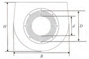 Figure 2 Front view of volute
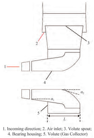 Figure 3 Front view of volute
The relative length is L = L/D, the relative height is H = H/D, the relative width is B = B/D, and the relative inlet diameter is D = (D − d)/D. The values of the above dimensionless parameters are shown in Table 1.
Table 1 Volute dimensionless parametersL H B D α1(°) α2(°) 0.69 1.61 1.82 0.35 8.33 19.36 The airflow at the outlet of an axial flow gas turbine is not completely axial but has a certain pre-swirl. Therefore, the inlet of the volute is set to seven rings with the same radial width as shown in Figure 2 to restore the actual intake flow field. Different inlet pre-swirl and mass flow boundary conditions are set at each inlet based on the known exhaust data at the turbine bucket outlet (Shi et al. 2019; Wu et al. 2019).
The total pressure loss, the relative standard deviation of the velocity, and the static pressure at the inlet of the volute are used in this paper to evaluate the performance of the volute, and the resultsare then compared and analyzed. The parameters are defined as follows.
The total pressure loss is defined as:
$$ \Delta P=\bar{P}_{\text {out }}^*-\bar{P}_{\text {in }}^* $$ (1) The total pressure loss ΔP intuitively reflects the resistance loss of the exhaust volute and is one of the important indicators for evaluating the performance of the volute in this paper (Wu 2008). In the above formula, Pout* and Pin* are the mass average total pressures at the volute outlet and inlet, respectively.
The static pressure recovery factor is defined as:
$$ C_P=\frac{\bar{P}_{\text {out }}-\bar{P}_{\text {in }}}{\bar{P}_{\text {in }}^*-\bar{P}_{\text {in }}} $$ (2) The turbine exhaust will undergo a process of static pressure recovery inside the volute; that is, the kinetic energy of the exhaust is converted into a rise in static pressure by the diffuser. If the airflow can sufficiently recover the static pressure, then such an airflow will positively affect the upstream components (Fu and Liu 2015; Farokhi 1987; Fu and Liu 2010). In the above formula, Pin and Pout are the average static pressures at the inlet and the outlet, respectively.
3 Calculation results and analysis
3.1 Numerical solution method
Most of the fluid domains of the exhaust volute are complex in shape. Thus, this paper uses a polyhedral hybrid mesh for mesh division, in which the exhaust duct part uses a hexahedral mesh, and the rest uses a tetrahedral mesh. Encryption processing and encryption in the wall boundary layer of the full model are also observed. Figure 4 shows the meshing of the volute and exhaust duct.
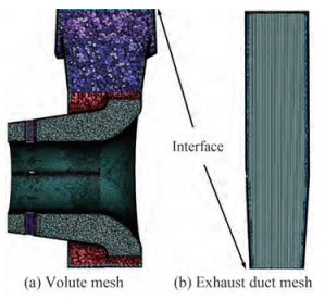 Figure 4 Schematic of volute meshing
The ANSYS FLUENT solver is used in this paper to solve the Navier–Stokes equations, and the Realizable k − ε turbulence model is also employed (Dong et al. 2020; Zhang 2008). The near-wall area is processed by the standard wall function, and the value of y+ is between 40 and 180. During the calculation process, the gradient discretization method is corrected by the warped surface gradient, so as to obtain a high gradient accuracy. The actual working conditions are presented as follows: the exhaust inlet of the volute turbine is set as the flow inlet, and the aver age static temperature is 674.2 K; the air inlet of the volute is the boundary condition of the pressure inlet, and the back pressure is set to zero; the outlet of the volute exhaust port is set as the backpressure zeropressure outlet boundary condition.
3.2 Grid independence verification
To improve the speed of numerical simulation, save computing resources, and eliminate the influence of the number of grids on the accuracy of calculation results, the grid independence verification is conducted with different numbers of grids generated in accordance with similar laws. The number of grids increases from 1.8 million to 7.3 million, and the total pressure loss defined by Equation (1) is used as the measurement standard. The ordinate is the value of the total pressure loss, and the abscissa is the number of grids. Figure 5 shows the change in the total pressure loss of the volute with the number of grids. The figure reveals that the grid-independent solution of the flow field can be obtained when the number of grids is 5.2 million. Therefore, 5.2 million was selected as the calculation grid number of the prototype volute and the subsequently modified volute.
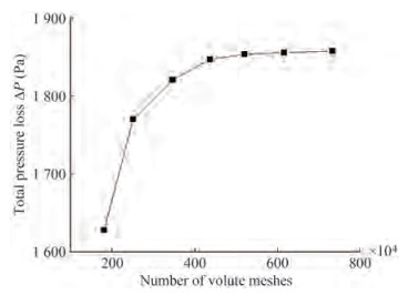 Figure 5 Volute mesh independence verification
3.3 Numerical simulation verification
This paper takes the volute whose geometric parameters and experimental results are disclosed in Dong et al. (2020) and Prakash et al. (2006) as the research object to verify the reliability of the numerical simulation method, and the geometric model is shown in Figure 6.
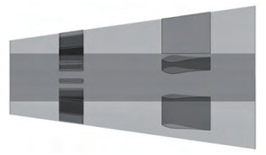 Figure 6 Geometric model of the volute
The same numerical simulation method is used for the calculation, and the meshing is shown in Figure 7. The numerical simulation results are compared with the experimental results, as shown in Table 2. Table 2 reveals that the numerical simulation results are in good agreement with the experimental values, and the error of the total pressure loss coefficient is 2.83%, indicating the reliability of the research method in this paper.
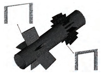 Figure 7 Grid of the computational domain of the exhaust voluteTable 2 Comparison of the calculated and experimental results
Inspection parameters Results in Dong (2020) (Pa) Analog value (Pa) Relative error (%) ΔP 515 529.57 2.83 3.4 Internal loss source
The diffusing structure, the gas collecting shell, the spout, and the exhaust passage of the exhaust volute are all geometrically symmetrical structures. In addition, Figure 8 shows the three-dimensional streamline diagram of the exhaust volute. The figure reveals that the spiral flow of the airflow inside the volute is symmetrically distributed, but not every area has the same flow law. The inlet is divided into four regions, namely Ⅰ, Ⅱ, Ⅲ, and Ⅳ, as shown in Figure 9, to explain the internal flow law of the volute comprehensively.
 Figure 8 Three-dimensional streamline diagram of volute
 Figure 9 Volute inlet partition
Figure 8 shows that the spiral flow of the flow field in the volute is extremely complex, and the mixing and interference between the airflows are observed. The airflow enters the volute from the diffuser and mixes with each other inside the gas collecting casing, resulting in an uneven distribution of the flow field velocity. The airflow in the Ⅰ and Ⅱ regions enters the gas collecting shell and is impacted by the incoming flow in the Ⅲ and Ⅳ regions, resulting in secondary mixing, which forms a more violent vortex region than the bottom.
Figure 10(a) presents the cloud map of the velocity distribution on the meridian surface of the volute, which shows a large area of low velocity at the bottom of the volute. After the high-speed airflow enters the volute, most of the high-temperature airflow directly impacts the wall surface due to the inertia of the airflow, causing a large speed loss.
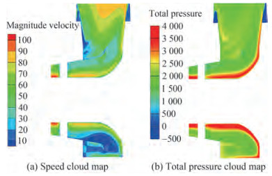 Figure 10 Distribution of the cloud map on the meridian surface of the volute
Figure 10(b) shows that the total air pressure near the wall of the bearing housing is high, and the total pressure gradually decreases along the outlet direction. A large number of airflow vortices exist at the bottom of the volute, the pulsation speed of the airflow is large, and a large amount of mechanical energy is converted into heat energy dissipation, thus increasing the resistance loss.
Figure 11 intuitively shows low-speed swirl flows in areas Ⅲ and Ⅳ at the bottom of the volute. Such a flow characteristic is mainly due to the following: the airflow entering the volute cannot be directly discharged from the volute vertically due to the structure of the bearing housing but flows along the bearing housing. When the airflow discharged from the diffuser hits the bottom wall of the gas collecting shell, a part of the airflow contacts the bearing housing to generate a vortex in zone a, and the other part of the airflow returns to the diffuser to generate a vortex in zone b.
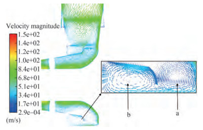 Figure 11 Velocity vector distribution on volute meridian plane
Figure 12 is the total pressure cloud diagram of the crosssection of the volute. The figure reveals that the gas on both sides of the volute is compressed, and the high-temperature gas flows to the outlet of the volute. The compression–expansion–compression process occurs, and the flow resistance increases.
 Figure 12 Total pressure distribution cloud map of volute cross section
The above analysis results show that the pressure loss of the exhaust volute is mainly attributed to the vortex flow and flow separation of the flow field inside the volute. The change in total pressure at the bottom and both sides of the volute is observed: part of the loss comes from the irregular expansion and compression as well as the mixing of the flowfor the above flow field characteristics.
4 Gas collection shell modification
4.1 Partial flow structure design of the volute bottom
According to the analysis of the distribution law of the flow field in the volute, the flow loss mainly comes from the bottom and both sides of the volute. The gas flow at the bottom is heavily dependent on the shape of the bottom of the volute. Dividing the flow at the bottom of the volute is an effective solution to solve the low-speed area and the swirl area at the bottom of the volute.
Scheme 1 adds a baffle plate near the end of the diffuser and the bearing housing, as shown in Figure 13(a), to improve the flow in zone a generated at the diffuser outlet. Simultaneously, a part of the bottom profile of the arc-shaped gas collecting case is concave upward and inward; therefore, the gas easily flows to both sides of the volute.
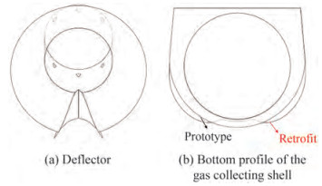 Figure 13 Partial flow modification scheme of volute bottom
4.1.1 Comparison of results
Table 3 shows the comparison of the performance indicators of Scheme 1 and the prototype volute. The bottom shunt design of Scheme 1 reduces the total pressure loss by only 4.6%, and the static pressure recovery coefficient increases by 13%. The resistance reduction effect is not ideal. In addition, the static pressure value of the volute inlet of Scheme 1 is increased by 17.2% compared with the prototype. According to the working principle of gas expansion in the turbine, a large static pressure at the inlet of the volute leads to a large back pressure of the turbine exhaust, which is unfavorable to the power output of the gas turbine (Wang 2010).
Table 3 Comparison of Scheme 1 and prototype performance indicatorsModel name Total pressure loss (Pa) Static pressure recovery coefficient Inlet static pressure (Pa) Prototype 1 881.13 −0.517 666.75 Plan 1 1 775.87 −0.45 781.4 4.1.2 Flow field analysis
Figure 14 shows the velocity vector diagram of the meridian surface of Scheme 1. The figure indicates that the eddy current strength of the two regions a and b has been significantly improved compared with the prototype volute.
 Figure 14 Scenario 1 meridian surface velocity vector
The design of Scheme 1 facilitates the easy flow of gas to both sides of the volute, and the diversion has a beneficial effect. Figure 15 shows that the expansion and contraction of the airflow still induce a large loss. Therefore, the volute shape must still be improved.
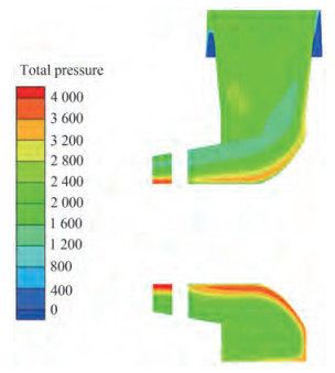 Figure 15 Scheme 1 pressure cloud map of the meridian plane
4.2 Gas collection shell chamfered design
The mixing ofairflow and irregular expansion and compression are the main causes of pressure loss on both sides of the volute. Scheme 2 is based on the model of Scheme 1, and a part of the intake side of the volute is beveled to control the regular expansion of the flow and reduce the loss effectively.
Figure 16 shows the meridian plane of the gas collecting shell, and the angle A between the cutting plane and the cross-section is defined as a chamfered angle (the angle in the figure is 12.5°). On the premise ofmaintaining the volute assembly in the unit, the influence of different cutting angles on the flow field in the volute was explored, and five different angles were selected from 12.5° to 90°. Among them, the bevel angle of Scheme 1 is 90°.
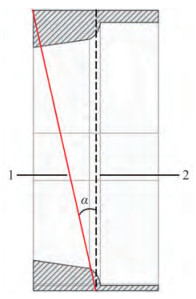 Figure 16 Schematic of the oblique cut design of the gas collecting shell
4.2.1 Comparative Results
The same numerical simulation method is used in this paper to calculate the five different chamfer angle modification schemes. The total pressure loss of each modification scheme and the distribution of static pressure at the inlet of the volute are shown in Figure 17.
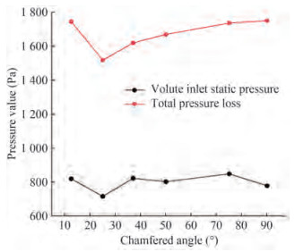 Figure 17 Comparison of the aerodynamic performance of each modification scheme
Figure 17 shows that the chamfer angle has a significant effect on the aerodynamic performance of the volute. With the increase in the chamfer angle, the total pressure loss of the volute shows a trend of decreasing first and then increasing. When the chamfer angle is 12.5°, the total pressure loss of the volute is larger than that of Scheme 1. When the chamfer angle increased to 25°, the total pressure loss of the volute decreased by 19.6% and then increased with the rise in the chamfer angle. This trend is due to the decreased improvement of the volute profile to the expansion of the airflow in the volute beyond a certain angle.
Figure 18 shows that the chamfered design of the volute can improve the static pressure recovery coefficient, which is larger than that of Scheme 1. The variation trend of the coefficient of restitution of the volute static pressure with the chamfer angle is similar to that in Figure 18. When the bevel angle is 25°, the static pressure recovery coefficient is reduced by 42.05% compared with the prototype. After 25°, although the static pressure coefficient is smaller than that of Scheme 1, the static pressure recovery coefficient gradually decreases with the increase in the bevel angle. Therefore, a reasonable combination design of chamfer angle and bottom split-flow structure can positively impact the aerodynamic performance of the volute.
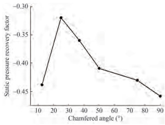 Figure 18 Static pressure recovery coefficient of each modification scheme
4.2.2 Flow field analysis
The meridian plane of the volute is selected to observe the change in the total pressure. Figure 19 shows that when the chamfer angle is 12.5°, the irregular expansion and compression of the gas inside the volute are observed, and the total pressure distribution on the walls on both sides of the gas collecting shell is extremely uneven. When the chamfer angle is 25°, this phenomenon is effectively improved, and the distribution of the total pressure field of the volute is relatively uniform except for the inlet of the volute.
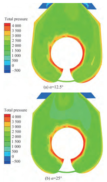 Figure 19 Total pressure cloud map of volute meridian plane
5 Conclusions
Through the research on the modification design of the gas collecting shell of a box-type exhaust volute, this paper draws the following conclusions.
1) One of the main reasons for the resistance loss of the volute lies in the formation of a relatively strong swirl by the airflow under the guidance of the upper and lower walls and side walls of the volute.
2) Dividing the flow at the bottom of the volute is an effective solution to solve the flow loss at the bottom of the volute, and the flow is heavily dependent on the shape of the bottom of the volute. Cutting a part of the volute close to the gas turbine side is the best solution to control the regular expansion of the flow and reduce the loss.
3) The low-speed area at the bottom of the volute and the irregular expansion and compression of the airflow on both sides should be comprehensively considered when the gas collecting casing is remodeled. The resistance loss of the volute can be effectively improved through a reasonable design. The combination of the appropriate chamfer angle and the bottom partial flow structure can reduce the total pressure loss by 19.6% and increase the static pressure recovery coefficient by 42.05%.
Acknowledgment: Supported by the National Science and Technology Major Project (No. J2019-Ⅲ-0017). -
Figure 1 3D model
Figure 2 Front view of volute
Figure 3 Front view of volute
Figure 4 Schematic of volute meshing
Figure 5 Volute mesh independence verification
Figure 6 Geometric model of the volute
Figure 7 Grid of the computational domain of the exhaust volute
Figure 8 Three-dimensional streamline diagram of volute
Figure 9 Volute inlet partition
Figure 10 Distribution of the cloud map on the meridian surface of the volute
Figure 11 Velocity vector distribution on volute meridian plane
Figure 12 Total pressure distribution cloud map of volute cross section
Figure 13 Partial flow modification scheme of volute bottom
Figure 14 Scenario 1 meridian surface velocity vector
Figure 15 Scheme 1 pressure cloud map of the meridian plane
Figure 16 Schematic of the oblique cut design of the gas collecting shell
Figure 17 Comparison of the aerodynamic performance of each modification scheme
Figure 18 Static pressure recovery coefficient of each modification scheme
Figure 19 Total pressure cloud map of volute meridian plane
Table 1 Volute dimensionless parameters
L H B D α1(°) α2(°) 0.69 1.61 1.82 0.35 8.33 19.36 Table 2 Comparison of the calculated and experimental results
Inspection parameters Results in Dong (2020) (Pa) Analog value (Pa) Relative error (%) ΔP 515 529.57 2.83 Table 3 Comparison of Scheme 1 and prototype performance indicators
Model name Total pressure loss (Pa) Static pressure recovery coefficient Inlet static pressure (Pa) Prototype 1 881.13 −0.517 666.75 Plan 1 1 775.87 −0.45 781.4 -
Burton Z, Hogg S, Ingram G (2012) A Generic low pressure exhaust diffuser for steam turbine research. ASME Turbo Expo: Turbine Technical Conference & Exposition, Copenhagen, Denmark, 455–466 https://asmedigitalcollection.asme.org/GT/proceedings/GT2012/44724/455/241166 Burton Z, Ingram G, Simon, Hogg S (2015) Efficient methods for predicting low pressure steam turbine exhaust hood and diffuser flows at design and off-design conditions. Journal of Engineering for Gas Turbines and Power 137(8): 82601–82601 https://doi.org/10.1115/1.4029599 Burton Z, Ingram GL, Hogg S (2013) A literature review of low pressure steam turbine exhaust hood and diffuser studies. Journal of Engineering for Gas Turbines & Power 135(6): 062001.1–062001.10 Chu SG (2013) Performance analysis of marine gas turbine exhaust volute. Master thesis, Harbin Engineering University, Harbin, 18–52. (in Chinese) Dong YX, Li ZG, Li J (2020) Numerical study on the effect of prerotation on the aerodynamic performance of gas turbine exhaust volute. Journal of Xi'an Jiaotong University (1): 116–124. (in Chinese) DOI: https://doi.org/ 10.7652/xjtuxb202001015 Farokhi S (1987) A trade-off study of rotor tip clearance flow in a turbine/exhaust diffuser system. ASME International Gas Turbine Conference & Exhibition, California, USA, 87-GT-229, V001T01 A084 Fu JL, Liu JJ (2010) Investigations of influential factors on the aerodynamic performance of a steam turbine exhaust system. ASME Turbo Expo 2010: Power for Land, Sea, and Air, Glasgow, UK, 2159–2169 Fu JL, Liu JJ (2015) Investigations on the improving aerodynamic performances of last stage steam turbine and exhaust hood under design and off design conditions. Journal of Thermal Science 24: 468–477. DOI: https://doi.org/ 10.1007/s11630-015-0810-2 Huang ED, Chu WL (2016) Optimal design of non-axisymmetric turbine exhaust volute. Propulsion Technology (10): 1839–1846. (in Chinese) DOI: https://doi.org/ 10.13675/j.cnki.tjjs.2016.10.005. Huang ED, Chu WL, Dong W (2017) An optimal design of a turbine exhaust volute. Journal of Aerodynamics (2): 455–462. (in Chinese) DOI: https://doi.org/ 10.13224/j.cnki.jasp.2017.02.025 Ji CJ, Wang YJ, Wang Xuejun, Mo Lixin (2009) Analysis and optimization of the internal flow of centrifugal compressor discharge volute. Chinese Journal of Mechanical Engineering (5): 311–316. (in Chinese) DOI: https://doi.org/CNKI:SUN:JXXB.0.2009-05-054 Li W (2021) Research on three-dimensional aerodynamic optimization design method of centrifugal compressor discharge volute. University of design method of centrifugal compressor discharge volute. University of Chinese Academy of Sciences (Institute of Engineering Thermophysics, Chinese Academy of Sciences). (in Chinese) DOI: https://doi.org/10.27540/d.cnki.ggrws.2021.000053 Li W, Zuo ZT, Hou HC, Liang Q, Lin ZH, Chen HS (2021) Parameterization and multi-objective optimization of centrifugal compressor volute based on genetic algorithm. Energy Storage Science and Technology (3): 1071–1079. (in Chinese) DOI: https://doi.org/ 10.19799/j.cnki.2095-4239.2020.0413 Mo ZY (2002) Numerical simulation of marine gas turbine exhaust volute. Master thesis, Harbin Engineering University, Harbin, 17–30. (in Chinese) Kato N, Sano H, Iio H (1995) Development of a turbocharger with a CFRP impeller. JSAE Review (1): 111. DOI: https://doi.org/ 10.1016/0389-4304(95)94861-G Prakash R, Sudhakar P, Mahalakshmi NV (2006) An experimental analysis of flow through annular diffuser with and without struts. ASME 2006 Internal Combustion Engine Division Spring Technical Conference, Aachen, Germany, 87–92 Shi WT, Yi WL, Ji LC (2019) Influence of uneven total inlet pressure on turbine aerodynamic performance. Aero Engine (3): 17–25. (in Chinese) DOI: https://doi.org/ 10.13477/j.cnki.aeroengine.2019.03.004 Tao CD, Gao J, Niu XY, Huo DC (2021) Research progress on aerodynamic performance of the interaction between exhaust volute and axial turbine. Thermal Power Engineering (10): 136–146. (in Chinese) DOI: https://doi.org/ 10.16146/j.cnki.rndlgc.2021.10.018 Vassiliev V, Irmisch S, Abdel-Wahab S, Granovskiy A (2012) Impact of the inflow conditions on the heavy-duty gas turbine exhaust diffuser performance. Journal of Turbomachinery 134(4): 041018. DOI:https://doi.org/ 10.1115/1.4003714 Wang Y, Tan X, Wang N, Huang D (2017) Aerodynamic design and numerical study for centrifugal turbine with different shapes of volutes. Applied Thermal Engineering, S1359431117340899. DOI: https://doi.org/10.1016/j.applthermaleng.2017.11.097 Wang ZY (2010) Research on performance of marine gas turbine exhaust ejector. PhD thesis, Harbin Engineering University, Harbin, 50. (in Chinese) Wu GQ (2008) Numerical simulation of compressor exhaust volute. Master thesis, Harbin Engineering University, Harbin, 38–39. (in Chinese) Wu WY, Zhong JJ, Lu HW, Kan XX (2015) Numerical study on the effect of strut on the performance of gas turbine exhaust volute. Journal of Dalian Maritime University (4): 47–52. (in Chinese) DOI: https://doi.org/ 10.16411/j.cnki.issn1006-7736.2015.04.019 Wu XC, Zhang JJ, Zhang J, Zeng ZH, Zhang Y, Liu XF, Liu XY, Zhou JM, Chen J (2019). Research on outlet velocity distribution of pre-direction fluid in gas turbine flowmeter. (eds. ) China Gas Operation Symposium on Safety and Safety (10th) and Proceedings of the 2019 Academic Annual Conference of the Gas Branch of China Civil Engineering Society (Volume 1) (pp. 43–49). Gas and Heat Magazine. (in Chinese) DOI: https://doi.org/10.26914/c.cnkihy.2019.022354 Xu X, Kang S, Jiang HD (2001) Numerical simulation of three-dimensional viscous flow in a low pressure steam turbine exhaust cylinder. Journal of Engineering Thermophysics (4): 430–433. (in Chinese) Xu X, Kang S, Jiang HD (2002) Numerical study of energy loss in low-pressure steam turbine exhaust cylinder. Journal of Beijing University of Aeronautics and Astronautics (6): 652–655. (in Chinese) DOI: https://doi.org/ 10.13700/j.bh.1001-5965.2002.06.013 Yu C (2019) Research and numerical analysis on the design method of turbine spiral case for pumps. Master thesis, Xi'an University of Technology, Xi'an, 1. (in Chinese) Yu Y, Ren W, Liu J (2019) A new volute design method for the turbo air classifier. Powder Technology 348: 65–69 https://doi.org/10.1016/j.powtec.2019.03.015 Zhang B, Sai QY, Li B (2022) Research on performance prediction of centrifugal compressor based on volute loss model. Journal of Chongqing Technology and Business University (Natural Science Edition) 39(1): 9–18. (in Chinese) DOI: https://doi.org/ 10.16055/j.issn.1672-058X.2022.0001.002 Zhang LN, Li HL, Yue GQ, Zhang LY, Zheng Q (2021) Structural optimization and performance analysis of turbocharger intake/exhaust volute. Internal Combustion Engine Engineering (4): 38–46+53. (in Chinese) DOI: https://doi.org/ 10.13949/j.cnki.nrjgc.2021.04.006 Zhang Y (2008) Research on regenerator and exhaust volute of marine ICR gas turbine. Master thesis, Harbin Engineering University, Harbin, 63. (in Chinese) Zheng YK, Wei YP (1985) Research on aerodynamic characteristics of axial-flow turbocharger turbine exhaust port. Journal of Shanghai Institute of Shipping and Transportation Science, Ministry of Communications (2): 60–72. (in Chinese) Zhu HG, Zhang RT, Luo GQ, Zhang B (2012) Investigation of hydraulic characteristics of a volute-type discharge passage based on CFD. Procedia Engineering 28: 27–32. DOI: https://doi.org/ 10.1016/j.proeng.2012.01.678
| Citation: |
Zhongyi Wang, Zeyu Zhang, Hao Fu, Jing Zhang, Meng Wang (2022). Optimization of Gas Turbine Exhaust Volute Flow Loss. Journal of Marine Science and Application, 21(3): 236-244. https://doi.org/10.1007/s11804-022-00294-7

|