-
Abstract
Development of man-packable, versatile marine surface vehicle with ability to rescue a drowning victim and also capable of carrying mission specific sensor is explored. Design thinking methodology is implemented by using existing equipment/platform with the addition of external attachment to make it a functional product. Iterative prototyping process with extensive testing to achieve user-centric solution. Individual prototypes and their possible sub-configurations with their integration and characteristics are studied and compared with numerical model, inferences obtained are utilised to improve for the next iteration. A novel hinge-clamp assembly enables this marine surface vehicle to operate in the event of an overturn, this phenomenon is further studied with the aid of a mathematical model (Pendulum in a fluid). This research project aims to demonstrate a multi-role unmanned surface vehicle.Article Highlights• Prototypes were made using the design thinking methodology, which were supported by extensive field testing to produce a user-centric solution.• A novel hinge-clamp assembly studied with the aid of a mathematical model (Pendulum in a fluid).• Discussion on the drag of toroidal shaped marine surface vehicles by using hydrostatic particular with help of numerical modelling. -
1 Introduction
The development of self-propelled marine vehicles dates back to the end of the 19th century by creation of torpedo with control system and later upgraded with gyroscope for direction control. Inventions such as steering control, engine and machines resulted in automation of marine vehicles. The first known remote-controlled boat dubbed as "Tele-automation" and later "Telekino" in early 20th century laid the foundation for Unmanned Surface vehicle (Motwani 2012).
The components of USV include hull and accessories, propulsion and power, guidance, navigation and control (GNC) modules, communication systems, data collection equipment and ground station (Liu et al. 2016). Hull must provide physical support, secure mounting points, carry payload and protect vehicle from collision with obstacles.
Hull moving through water creates resistance; this resistance should be overcome with net force provided by propulsion. Propulsion consists of three parts; an energy source, an engine and propulsor. The choice of the energy source determines the engine, the type of marine environment determines the propulsor. Guidance, navigation and control are defined as motion planning, sensing and control of vessels to reach the destination. Guidance is the determination of path to destination and desired changes in acceleration, velocity and rotation to follow the path. Navigation is the current status of vehicle position and velocity with respect to path. Control is the manipulation of forces and moments required to maintain the path. Communication systems include on-board communication of subsystems within themselves and wireless/wired communication between vehicle and ground station. Improvements and development in control systems, Global Positioning System (GPS), high speed wireless communication has resulted in reliable autopilots that provide flexibility of choosing different levels of autonomous capability. This information can be passed to a ground station/command station displaying with real time status of the vehicle enabling the operator to make informed decisions. Unmanned surface vehicles can also be deployed at water bodies to collect data using variety of sensors such as Conductivity, temperature, depth (CTD), echo sounder or Sound Navigation Ranging (SONAR), temperature, chlorophyll etc. Wide variety of civilian applications such as sea-bed mapping, water profiling, marine wildlife census and sea erosion can be realised with use of above sensors. USV enables easy access to shallow depths hence preferred for developing hydrography charts (Specht et al. 2019).
In present era, unmanned surface vehicle is widely utilised for search and rescue (SAR) operation because of access to localization; communication, payload carrying capacity and ability for deployment in emergency relief operations (Jorge et al. 2019). SAR robots must be agile, provide situational awareness, communicate with command station, carry sensor and payloads, on-board power, easy to control and deploy, thus mitigating the risk and for rescue responders. Three category of rescue robots based on size are, man-packable, man-portable and maxi-size. Man-packable robot seems an ideal choice for victim rescue in shallow water surface for ease of deployment, faster response and low resource requirement (Murphy et al. 2008). The EMergency Integrated Lifesaving lanYards (EMILY) (Hydronalix 2018), U-safe (Noras 2017), Remote controlled lifesaving buoy (Intercool 2019) and Dolphin1Smart lifebuoy (OceanAlpha 2019) form man-packable commercially available SAR robots.
Designing a marine vehicle involves identifying parameters, terminology and calculations (Misra 2015). In the design process, it's necessary to understand geometrical properties of the vessel to estimate its stability in the fluid and the forces and moments acting on it. Further, the system's hydrodynamic behaviour has to be evaluated through basic theoretical calculation and experimental results for characterization of the USV (Biran and López-Pulido 2013). Section 2 describes the methodology used in carrying out the research, also includes the content pertaining to the development of the two prototypes, their components, system identification and characteristics. Section 3 details results, discussion and conclusion.
2 Materials and methods
2.1 Research methodology
Design thinking is a user-centric, solution-oriented, iterative process aimed at providing user required solution (Stanford 2010). A Modified design methodology has been incorporated into this project to obtain a affordable technological solution within the limited time frame (Dam and Siang 2020).
In the first stage the problem faced by society was identified, i. e develop a multi-role unmanned marine surface platform that would be used to save a drowning victim and bring him to safety thus mitigating the risk for a lifeguard and also act as a sensor platform depending on the mission requirement.
In second stage extensive literature survey in the domain of drowning, search and rescue robotics, unmanned surface vehicle for disaster mangement, existing lifesaving equipments, diverse application of ring buoy and design of marine vehicles were carried out. In third stage, ideas were generated considering the framework of search and rescue robots (Figure 1) and basic elements of unmanned surface vehicles were selected accordingly.
 Figure 1 Research framework
Framework for a search and rescue robots are:
1) Low developmental cost: must be inexpensive and reliable so that it can be built, maintained, and deployed at a fraction cost of commercial alternatives.
2) Simplicity of design: the design of the robot should be modular and straightforward.
3) Reliability: already existing sea-worthy hardware would reduce time required for experimental testing.
4) Light-weight and easily deployable: faster response to the disaster ensures a high success rate to save the victim; hence lightweight and easily deployable equipment would aid first responders to act quickly.
5) Payload capability: the robot must be capable of carrying the victim from a hot zone to shore. Additionally, variety of sensors could be mounted (Shetty et al. 2020).
Displacement type vessel (Erünsal 2015) with a multi-hull satisfies our criteria, shortcomings in maneuverability can be overcome by differential steering. This project uses combination of materials taking into account the corrosion effect, the moments and forces acting on components. Focusing on the framework, building a custom hull is an unviable option hence ring buoy/lifebuoy (Marine 2015) is best suited as hull and also as a flotation device. Acrylic for mounting thrusters and watertight enclosure, nut and bolts for securing auxiliary elements with the ring buoy. The watertight enclosure consists of a hollow acrylic cylinder; the open ends are enclosed by aluminium flanges with grooves for O rings and bulkhead connectors mounted on end plate.
Our application requires 12 V DC supply hence a lithium-polymer battery of 11.1 V DC, 2.2 Ah is preferred. With energy source has electric power, the engine of choice is brushless direct current electric (BLDC) motor. Our requirement corresponds to high thrust and low speed hence kort nozzle with fixed pitch propellers of short and wide blades are incorporated as propulsor. Commercially available thruster with 45 N thrust (Robotics 2020) with compatible Electronic Speed Controller (ESC) is used.
Simplified Guidance, Navigation and Control (GNC) prefers the Line of sight method i.e straight path towards destination. Autopilot and Remote Control Unit are two components selected in our application. Developing an autopilot system is out of the scope of this project; hence a commercially available alternate (Meier et al. 2011) is selected. A remote control unit consists of operator held transmitter that communicates with the receiver onboard the vehicle. The transmitter has physical controls that are manual input for control of actuators, this is received as radio signals by the receiver, forwarded to flight controller or actuators directly in absence of former. This project utilises 2.4 GHz, 6 channel commercially available trans‐ mitter and receiver system. The ground control station consists of a computing device with flight management software connected to a telemetry device in addition to a hand held transmitter. The operator could manually change the input in the transmitter and instantly check the vehicle's status, thus being situational aware of the surroundings and making informed decisions (Team 2016).
The fourth stage involves theoretical calculation for designing of marine vehicle such as positions of centre of gravity, centre of buoyancy, centre of floatation by weighted average method; reynolds number, froude number, resistance, effective power by empirical formula (Bertram 2011). Below explains the formulas used for calculating resistance. The coefficient of total resistance is
$$ C_T=R_T /\left((1 / 2) \times \rho \times A \times v^2\right) $$ (1) where RT is the total resistance (N), ρ is fluid density (kg/m3), A is wetted surface area of vessel (m2) and v is hull speed (m/s).
The coefficient of total resistance in terms of dimen‐ sionless coefficients is given as
CT=CV+CW, where CV is coefficient of viscous resistance and CW is coefficient of wave making. Coefficient of Viscous Resistance CV includes friction of the fluid on the vessel and hull form. The empirical equation from the International Towing Tank Conference (ITTC) givenby
$$ C_V=C_F+\left(K \times C_F\right) $$ (2) where CF is skin friction component of viscous resistance, (K×CF) = viscous pressure drag component of viscous resistance (Figure 2).
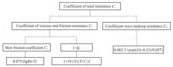 Figure 2 Calculation for resistance
The skin friction coefficient CF assumes the hullisa flat plate and function of Reynolds number. The ITTC1957 formula incorporates some three-dimensional friction effects and is defined as:
$$ C_F=0.075 /((\lg R e)-2)^2 $$ (3) The form factor K includes hull form effect given by
$$ K=19 \times\left(V /\left(T \times L^2\right)\right)^2 $$ (4) where V is volume displaced (m3), T is draft (m) and L is length of the vessel (m).
Similar empirical equation is also applicable for coefficient of wave making resistance
$$ C_W=0.0022 \times \exp ((F n-0.33) / 0.057) $$ (5) where Fn is Froude number.
Effective Power is given by the total resistance multiplied by hull speed gives the effective power. The effective power PE to tow the vessel in calm water, where PE = (R×v).
Hull speed or displacement speed v is the maximum speed a vessel can attain, i.e the wavelength of a vessel's bow wave is equal to the vessel's waterline length. Exceeding hull speed, the vessel gets trapped in its own wave system. The empirical formula given by v = 1.41×$\sqrt{(LWL)}$ in m/s.
The fifth stage is prototyping. The initial aim is to validate the proof of concept by producing a basic version of remotely operated ring buoy surface vehicle. This is to keep the cost low and understand its behaviour. This iterative process first learns from initial prototype by testing with the user, learning is then expanded to reach the final solution. Problem areas and variables are identified and best possible solution is implemented taking into account the framework.
The sixth stage field testing was carried out, measurement and observation were recorded. Testing refines the prototype and helps to provide user centric solution. Extensive testing was carried out in Hydraulic lab reservoir, institution Swimming pool and Shambhavi River, Hejmady. Fishermen, lifeguards, swimming pool personnel, and relevant stakeholders' valuable advice and opinions were considered to improve the system.
In seventh stage, numerical modelling data and experimental observations were compared and inferences derived were utilised for developing new prototypes.
2.2 Prototype development
The detailed discussion of the first prototype has been explained in Shetty et al. (2020). The findings of the first prototype are; thrust provided by one thruster was insufficient to propel the surface vehicle with the victim on-board and the victim due to exhaustion maynot able to control the vehicle path hence differential steering would provide more control over the vehicle. The second prototype consists of two thrusters, their accompanying electronic speed controllers, battery, receiver and Battery Eliminator circuit (BEC) mounted on a laser cut acrylic trayenclosed in a watertight container, this subsystem is then mounted onto a ring buoy. The operator and the transmitter are located in the ground station. One of the thruster has clockwise propeller and other the counter clockwise propeller, this ensures the torque from thrusters is cancelled out operating along the same axis. The length of prototype is 0.804 m, breadth is 1 m and draft of 0.032 m. The trim angle was found to be 5° (Figure 3), total mass of the system is 5.493 kg.
 Figure 3 Trim of prototype 2
Two sub-configuration of prototype 2 were developed by addition of a cylindrical dead weight system that could be varied from 0.65 kgf to 5.63 kgf (Figure 5), additional 2 kgf can be added on this arrangement. The prototype tobe deployed as rescue platform must provide flotation tothe victim i.e a 100 kgf person requires 5 kgf of buoyancy to stay afloat, hence the total mass of prototype was 11.863 kg with trim angle of −3° (Figure 4) in rescue configuration. A sensor platform must be able to carry the sensor and transmit data to ground station, this platform had the total mass of 9.863 kg with trim angle of 0.5° (Figure 5). The dead weight were placed at a distance of 185 mm from the center of the buoy. The testing was carried out on 25 November 2019 and 30 December 2019 at Institution Swimming Pool, differential control and payload capability in different configurations were studied. Refer Table 1 for Numerical modelling data for prototype 2 and its configuration.
 Figure 4 Trim of rescue platform
 Figure 5 Trim of sensor platformTable 1 Weight, resistance and effectivepower for prototype 2 and its sub-configurations
Name Unit Prototype 2 Prototype 2 with person on-board Sensor platform Rescue platform Weight N 54 122.45 96.8 116.4 Total resistance RT N 22.4 42.1 25.2 26.4 Effective power required W 28.34 53.2 32 33.35 Two major inferences were derived from testing of second prototype; first, whileperforming the mission, the USV maybe overturned causing malfunction, hence a mechanism had to be envisioned to flip the thrusters to be in water, second, autopilot system had to be implemented for situational awareness and status of the vehicle (Figure 6).
 Figure 6 Electronics block diagram of prototype 3
The third prototype built upon these inferences by attaching a flipping mechanism to thrusters for ensuring them to be in water and to maintain identical configuration, the horizontal plane of the water-tight container is coincided with horizontal plane of ring-buoy. The length of prototype is 0.804 m, breath is 0.848 m and draft of 0.031 m. The trim angle was found to be 3° for both configuration (Figure 7 and 8), mass of the prototype is 5.616 kg. Refer Table 2 for numerical modelling data for prototype 3. The swimming pool test was carried out on 09 March 2020. The USV was evaluated for control, function when flipped and hinge clamp assembly behaviour. Oscillation of hinge-clamp assembly was studied with help of mathematical model.
 Figure 7 Trim prototype 3 upright configuration
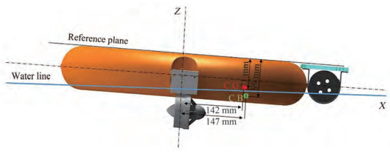 Figure 8 Trim prototype 3 over-turned configurationTable 2 Weight, resistance and effective power for prototype 3
Name Unit Prototype 3 Prototype 3 with person on-board Weight N 55 123.86 Total resistance RT N 17.665 35.22 Effective power W 22.33 44.53 2.2.1 Hinge clamp assembly
The installation of thruster on the hull is by means of a hinge assembly (Figure 9). This assembly consists of a plate that attaches to the hull through M12 bolt and hinge with clamp holds the thruster. There are total of two such assemblies on the either side of the hull for differential steering. The assembly flips when the buoy flips due to combination of external torque and gravity. A phenomenon occurs where if the applied torque is greater than mass moment of inertia of the clamp-thrusters assembly then the hinge oscillates around perpendicular to its axis, this in-turn moves the thrusters towards the free surface thus sucking in air and reducing efficiency and thrust. To analyse this problem the hinge clamp-thrusters assembly is approximated to be pendulum in water. Following section describes the phenomenon, gives a mathematical model and results in appropriate design.
 Figure 9 Front view and side view of hinge clamp assembly
2.2.2 Experimental observation
The above Figure 10 (upright position) depicts the forward motion i. e clockwise motor moves clockwise to give forward thrust, counter-clockwise motor moves counter-clockwise to give forward thrust. As a result a counter torque is produced (Newton's third law of motion) as shown in the figure. If the applied torque is greater than mass-moment of inertia of the clamp-thrusters assembly then the assembly oscillates thus the thruster's moves towards free surface.
 Figure 10 Front view of upright configuration
When flipped (overturned position) as shownin Figure 11, the motors change their position, vice-versa phenomenon is observed.
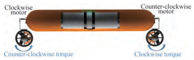 Figure 11 Front view of over-turned configuration
2.2.3 Mathematical model
Assumptions made are:
1) Hinge-Clamp assembly with thruster is assumed to bependulum inwater.
2) Hinge-Clamp assembly with thruster can be approximated as point mass at a distance b + r from the pivotpoint.
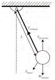 Figure 12 Forces acting on Pendulum in fluid (Leme and Oliveira 2017)
3) Bearing forces and friction are neglected.
The restoring torque acts at point O. Moment for this restoring is taken along the tension force of the length (Figure 13).
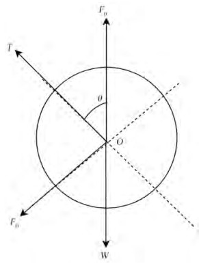 Figure 13 Free body diagram of Pendulum in fluid
ΣM along length = 0 or = Counter torque τ
$$ \tau_{\text {total }}=(I \times \alpha) $$ (6) where I is the mass moment of inertia, torque τ and angular acceleration α (Fitzpatrick 2018)
$$ \tau_{\text {total }}=(W L \times \sin \theta)-\left(F_B \times L \sin \theta\right)+\left(F_D \times L\right) $$ (7) Effective weight W, buoyancy force FB and drag force FD are inputs to obtain torque (Figure 15). Drag force is calculated by
$$ F_D=\left(0.5 \times C_D \times \rho_{\text {Water }} \times A \times v^2\right) $$ (8) 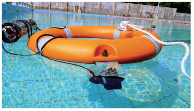 Figure 14 Trim observed in prototype 2
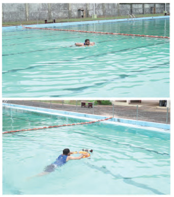 Figure 15 Rescue operation with victim onboard
CD is assumed to be 1.1.
Therefore (Table 3), FD is 4.343 3×10⁻⁴ N, hence, τ is 0.034 N·m.
Table 3 Calculation to determine drag force and torque acting on Hinge Clamp AssemblyVariable Formula Numeric value L b + r 0.113 m θ 5° 0.087 2 rad v L×(θ/t) 9.85×10⁻³ m/s mEquivalent mClamp + mThruster 0.355 kg mEffective mEquivalent + mAddedmass 0.543 8 kg FB ρWater×Volumedisplaced×g 1.84 N IEffective mEffective×L2 6.94 ×10⁻³ kg·m2 A (b+r)×a 8.136×10⁻³ m2 According to Moore et al. (2010), a counter torque is applied by the motor when producing thrust. This counter torque is opposite to rotation of the propellers but has the same magnitude (Newton's third law).
Torque produced by thruster
$$ P \times 60 /(2 \times \pi \times N)=T $$ (9) From thruster specification sheet (Robotics 2020), all Max values are taken Maximum torque produced when reversed TR is 0.657 N·m and forward TF is 0.640 7 N·m. Therfore, the Mass moment of inertia of the hinge– clamp assembly has to be greater than this torque to stop the moment during thrust.
3 Results and discussion
The testing of prototype 2 was carried outin Swimming pool (Figure 14), it was able to perform a lap differential control was found tobe appropriate and was capable of carrying 80 kg person with average speed 0.625 m/s back to safety (Figure 15). The prototype with configuration of sensor platform was found to be the most stable and steer accurately with average speed of 0.675 m/s (Figure 16). Gyroscopic couple effect was observed in rescue platform, its average speed was found to be 0.656 m/s (Figure 17). Readings taken from inclinometer were found to agree with trim calculated from Computer aided design models. Institution swimming lifeguards and personnel present during testing provided valuable inputs regarding control and rescue, this was considered for prototype 3.
 Figure 16 Sensor platform configuration
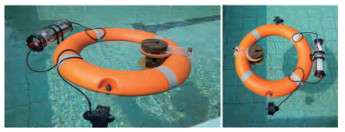 Figure 17 Rescue platform configuration
In prototype 3, hinge-clamp assembly is able to position the thrusters always inside water, thus thrusters are able to function with maximum efficiency and avoid sucking in air. It also ensures low water-plane area thus improving stability. Water-tight enclosure is positioned in the middle, hence the characteristics of the system in upright and over turned are similar as confirmed by its Center of Gravity (C.G) and Center of Buoyancy (C.B) coordinates. Resistance, longitudinal and transverse metacentric height are of lower value compared to prototype 2.
For both the prototypes, hull speed is greater than 1.2 m/s, froude number is calculated as 0.36 i.e displace ment type hull and reynolds number are calculated in the range of 1.42−1.2×10⁶ i.e turbulent region.
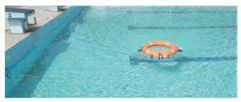 Figure 18 Prototype 3 upright configuration testing in swimming pool
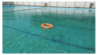 Figure 19 Prototype 3 overturned configuration testing in swimming Pool
4 Conclusions
Literature survey on buoys opened up the possibility of research gap on study of drag calculation for toroidal shaped floating structures. This research paper studies the drag of toroidal shaped marine surface vehicle by using hydrostatic particulars with help of numerical modelling. Different weight configurations and its effects on performance of the vehicle are discussed. Additionally, Hinge clamp assembly is mathematically modelled as pendulum in fluid and discussed. The societal application of this research project is to demonstrate a reliable mulit-role marine surface vehicle that would reduce deaths by drowning, act as oceanographic sensor platform and also aid population dwelling close to water bodies in their occupational activity.
Acknowledgements: We wish to acknowledge National Institute of Technology Karnataka, Surathkal and Centre for System Design, NITK for providing the resources and guidance to complete this research work. Special mention to Aquib Nadaf, Dinesh, Kiran Katari, Dr Praveen Shenoy, Suveen Poojary, Tejas Pethkar and Vishwas for their roles in Photography, Videography, Field testing Support and Research Input. -
Figure 1 Research framework
Figure 2 Calculation for resistance
Figure 3 Trim of prototype 2
Figure 4 Trim of rescue platform
Figure 5 Trim of sensor platform
Figure 6 Electronics block diagram of prototype 3
Figure 7 Trim prototype 3 upright configuration
Figure 8 Trim prototype 3 over-turned configuration
Figure 9 Front view and side view of hinge clamp assembly
Figure 10 Front view of upright configuration
Figure 11 Front view of over-turned configuration
Figure 12 Forces acting on Pendulum in fluid (Leme and Oliveira 2017)
Figure 13 Free body diagram of Pendulum in fluid
Figure 14 Trim observed in prototype 2
Figure 15 Rescue operation with victim onboard
Figure 16 Sensor platform configuration
Figure 17 Rescue platform configuration
Figure 18 Prototype 3 upright configuration testing in swimming pool
Figure 19 Prototype 3 overturned configuration testing in swimming Pool
Table 1 Weight, resistance and effectivepower for prototype 2 and its sub-configurations
Name Unit Prototype 2 Prototype 2 with person on-board Sensor platform Rescue platform Weight N 54 122.45 96.8 116.4 Total resistance RT N 22.4 42.1 25.2 26.4 Effective power required W 28.34 53.2 32 33.35 Table 2 Weight, resistance and effective power for prototype 3
Name Unit Prototype 3 Prototype 3 with person on-board Weight N 55 123.86 Total resistance RT N 17.665 35.22 Effective power W 22.33 44.53 Table 3 Calculation to determine drag force and torque acting on Hinge Clamp Assembly
Variable Formula Numeric value L b + r 0.113 m θ 5° 0.087 2 rad v L×(θ/t) 9.85×10⁻³ m/s mEquivalent mClamp + mThruster 0.355 kg mEffective mEquivalent + mAddedmass 0.543 8 kg FB ρWater×Volumedisplaced×g 1.84 N IEffective mEffective×L2 6.94 ×10⁻³ kg·m2 A (b+r)×a 8.136×10⁻³ m2 -
Bertram V (2011) Practical ship hydrodynamics. Elsevier, Oxford, United Kingdom, 65–68 Biran A, López-Pulido R (2013) Ship hydrostatics and stability. Butterworth-Heinemann, Oxford, United Kingdom, 1–182 Dam RF, Siang TY (2020) Five stages in the design thinking process. Available from https://www.interaction-design.org/literature/article/5-stages-in-the-design-thinking-process [Accessed on 06 May 2020] Erünsal K (2015) System identification and control of a sea surfacevehicle. Master thesis, Middle EastTechnical University, Ankara, Turkey, 1–3 Fitzpatrick R (2018) Oscillations and waves: an introduction. CRC Press, 12–14 Hydronalix (2018) Emily by hydronalix. Available from https://www.hydronalix.com//. [Accessed on 30 April 2019] Intercool (2019) Remote controlled lifesaving buoy. Available from http://www.interzcool.com/html_products/remote-controlled-buoy-1618.html. [Accessed on 4 May 2019] Jorge VA, Granada R, Maidana RG, Jurak DH, Goncalves LM, Amory AM (2019) A survey on unmanned surface vehicles for disaster robotics: Main challenges and directions. Sensors 19(3): 702. DOI: https://doi.org/ 10.3390/s19030702 Leme JC, Oliveira A (2017) Pendulum underwater — an approach for quantifying viscosity. The Physics Teacher 55(9): 555–557. DOI: https://doi.org/ 10.1119/1.5011833 Liu Z, Zhang Y, Yu X, Yuan C (2016) Unmanned surface vehicles: An overview of developments and challenges. Annual Reviews in Control 41: 71–93 https://doi.org/10.1016/j.arcontrol.2016.04.018 Marine S (2015) Ringbuoy. Available from http://www.solasmarine.com/trades_division/lifebuoyring.php. [Accessed on 4 May 2019] Meier L, Tanskanen P, Fraundorfer F, Pollefeys M (2011) Pixhawk: A system for autonomous flight using onboard computer vision. IEEE International Conference on Robotics and Automation, 2992–2997. DOI: https://doi.org/10.1109/ICRA.2011.5980229 Misra SC (2015) Design principles of ships and marine structures. CRC Press, 109–149 Moore SW, Bohm H, Jensen V, Johnston N (2010) Underwater robotics: science, design & fabrication. vol 770, Marine Advanced Technology Education (MATE) Center Monterey, 1–443 Motwani A (2012) A survey of uninhabited surface vehicles. Marine and Industrial Dynamic Analysis, Plymouth University, Plymouth, United Kingdom, Technical Report MIDAS. SMSE. 2012. TR. 001 Murphy RR, Tadokoro S, Nardi D, Jacoff A, Fiorini P, Choset H, Erkmen AM (2008) Search and rescue robotics. Springer handbook of robotics 1151–1173 Noras (2017) Usafe by noras performance. Available from https://www.norasperformance.com/en/u-safe-2//. [Accessed on 3 May 2019] OceanAlpha (2019) Dolphin 1 smart lifebuoy by oceanalpha. Available from https://www.oceanalpha.com/product-item/dolphin-i//. [Accessed on 3 May 2019] Robotics B (2020) Underwater thruster. Available from https://bluerobotics.com/store/thrusters/t100-t200-thrusters/t200-thruster/ [Accessed on 3 December 2018] Shetty NB, Rao N, Umesh P, Gangadharan KV (2020) Remotely operated marine rescue vehicle. AIP Conference Proceedings 2247: 020022. DOI: https://doi.org/ 10.1063/5.0004147 Specht M, Specht C, Lasota H, Cywinski P (2019) Assessment of the steering precision of a hydrographic unmanned surface vessel (USV) along sounding prxxofiles using a low-cost multi-global navigation satellite system (GNSS) receiver supported autopilot. Sensors 19(18): 3939. DOI: https://doi.org/ 10.3390/s19183939 Stanford HPIoD (2010) An introduction to design thinking process guide. Available from https://web.stanford.edu/~mshanks/MichaelShanks/files/509554.pdf/. [Accessed on 06 November 2018] Team AD (2016) Mission planner. Available from https://ardupilot.org//. [Accessed on 06 March 2020]
| Citation: |
Nishan B Shetty, Pruthviraj Umesh, KV Gangadharan (2022). Multi-role Remotely Operated Marine Surface Vehicle. Journal of Marine Science and Application, 21(3): 219-227. https://doi.org/10.1007/s11804-022-00283-w

|