Experimental Study on the Configuration Hydrodynamics of Trimaran Ships
https://doi.org/10.1007/s11804-022-00281-y
-
Abstract
This paper presents experimental results on configuration hydrodynamics. Three models are used in the model tests, which are typical of hard, round, and soft chines. Although specific values are different, the influence patterns are similar in the three ship models. A set of different outrigger positions is investigated in calm water and regular waves. A variety of interesting phenomena are observed, among which the splash resistance is the dominant component for a trimaran at high speeds (with Froude number Fr > 0.6). If two small outriggers are placed inside Kelvin's wave systems of the main hull, a strong splash appears, resulting in a significant resistance increase. Moreover, short and long waves cannot be neglected, for they may excite the motions of much smaller outriggers. This condition leads to non-vanishing heaving at high-frequency and non-normalized pitches at low frequencies. Based on the tests, three spectra of optimum configurations for resistance, longitudinal motions, and transverse motions are presented. These results reveal the optimum configurations of a trimaran hull in terms of hydrodynamic performance, thus providing a very powerful tool for optimum design of trimaran ships.Article Highlights• A series of experimental tests on different arrangements of main and side hulls show that positions of side hulls relative to the main hull exhibit significant influences on hydrodynamic performance of trimaran ships.• The optimum configurations at different speeds in calm water and waves are presented, which indicate that forward trimaran performs better at high speeds and backward trimaran performs better at low speeds.• Experimental results reveal the existence of splash resistance at high speeds (Froude number greater than 0.6). -
1 Introduction
A trimaran comprises a long main hull with two small outriggers (side hulls) on both sides attached to the main hull by lateral beam. Although trimarans had been used by Polynesians long ago, the first large-size trimaran ship had not been conceptualized until the 1990s by researchers at University College London (UCL) (Andrews and Zhang 1995). The Royal Navy was soon ready to build a trimaran demonstrator ship RV Triton (Naval Technology 2001), which was 90 m long, 22 m wide, and 20 kn fast. This was soon overtaken in 2000 by the Austal Aluminum trimaran Benchijigua Express (Ship Technology 2006), which was 102 m long and 40 kn fast. Trimaran hulls may achieve high speeds beyond our previous expectations. Thus, research interests in trimaran ships have greatly intensified in recent years.
Although the displacements of side hulls are small compared with those of the main hull, their longitudinal and lateral positions exhibit important influences on the behaviors of resistance(Ackers et al. 1997) and motions of trimaran hulls (Hebblewhite et al. 2007; Khoob et al. 2021). In fact, UCL researchers already realized the strong interaction among hulls of a trimaran ship as early as in the 1990s (Andrews and Zhang 1995). This is particularly true at high speeds. The challenge is that such influences are complicated, owing to their case dependency (Dogrul and Yildiz 2022; Wang et al. 2009; Zhou et al. 2015; Xu and Zhang 2011). The best position for one specific speed may turn out to be a very bad one for another speed (Wang et al. 2009; Zhou et al. 2015). This phenomenon has been observed in experiment tests (Khoob et al. 2021; Dogrul and Yildiz 2022) and subsequent numerical studies (Poundra et al. 2017; Yildiz et al. 2020; Liu et al. 2021). The strong interference between the main and side hulls results in the complexity of trimaran hull configuration. Therefore, it is necessary to optimize configurations on a case-by-case basis (Poundra et al. 2017; Yildiz et al. 2020). Accordingly, recent years have witnessed increasing research interest in the configuration optimization of trimaran ships (Liu et al. 2021; Wang et al. 2021; Lv et al. 2022).
The above-mentioned research leads us to the conclusion that the configuration of the three hulls has significant influences on resistance and ship motions in waves. Hence, it is important to clarify the influence patterns for the different configurations of trimaran hulls. Moreover, a universal optimum position of side hulls for all speeds does not exist (Zhou et al. 2015; Liu et al. 2021; Wang et al. 2021).
Therefore, the problem to be solved in this study is to determine the spectrum of optimum configurations for trimaran ships based on the test results of three models. To do so, a series of experimental tests were conducted, which results are reported in this paper.
2 Model experiments
2.1 Test models
The body plan of the model trimaran, which is denoted as Model A, is shown in Figure 1, and the main particulars are given in Table 1.
 Figure 1 Body plan of Model ATable 1 Main particulars of Model A
Items Main hull Side hulls Length of waterline (m) 4.000 1.000 Breadth of waterline (m) 0.358 0.085 Draft (m) 0.170 0.100 Displacement (m3) 0.129 0.004 5 Wetted Surface (m2) 1.899 0.201 Block coefficient 0.530 0.524 Prismatic coefficient 0.769 0.746 The layout of the hulls is shown in Figure 2. The origin of the coordinates is the intersection of the central longitudinal profile, midship section, and designed waterline. The lengths of the main hull and side hull are denoted as Lm and Ls, respectively. Similarly, the breaths are denoted as Bm and Bs, respectively. Two key variables, a and b, are introduced to denote the longitudinal and transverse positions of the side hulls, respectively. a > 0 implies that the midship section of the side hull is in front of the main hull. The variable b is the transverse distance between the central longitudinal profiles of the main hull and side hulls. The value of b is always positive. A series of configurations are designed, which are shown in Table 2. The configurations that the two side hulls placed at both sides of the bow, midship, and stern of the main hull are denoted as the forward trimaran, middle trimaran, and aft-ward trimaran, respectively.
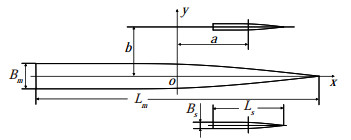 Figure 2 Trimaran configurationTable 2 Configurations of trimaran Model A
No. a/Lm b/Bm Layout ① -0.325 1.955 
② -0.250 1.955 ③ -0.175 1.955 ④ 0.0 1.955 ⑤ 0.250 1.955 ⑥ -0.175 1.117 ⑦ -0.325 1.117 2.2 Experimental setup
The experiments were conducted in the towing tank, Dalian University of Technology, an ITTC member. The tank is 160 m long, 7 m wide, and 4 m deep, with wave dampers on the side wall. There is a wave generator at one end of the tank, which can make regular and irregular waves with a maximum wave height of 0.4 m, as shown in Figure 3.
 Figure 3 Wave generator composed of 20 small plates
The model trimaran was attached to the carriage, whose maximum speed is 8 m/s. Resistance and motion responses (heaving, pitch, and roll) were measured using the resistance sensor, heaving sensor, and gyroscope, as shown in Figure 4. The picture of the model tests for Model A in the towing tank is shown in Figure 5.
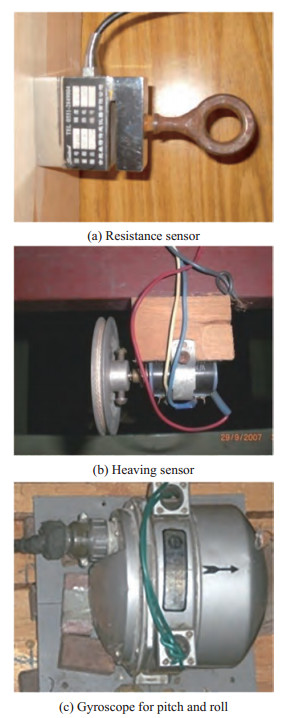 Figure 4 Apparatus used for Model A
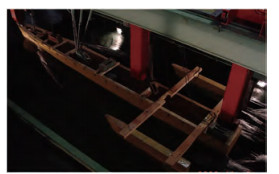 Figure 5 Model tests for Model A in the towing tank
A series of experiments were conducted for all the configurations, including resistance tests in calm water and regular waves and heave, roll, and pitch tests in regular waves.
3 Experimental results
The results obtained from the experiments were plotted in a series of curves to analyze the influence of the configuration on the trimaran hydrodynamics.
3.1 Resistance in calm water
The resistance measured in calm water tests is the total resistance. The time history of the total resistance of a typical configuration at Fr = 0.857 is shown in Figure 6. Small oscillations in the curve can be observed due to the strong interference at the high speed.
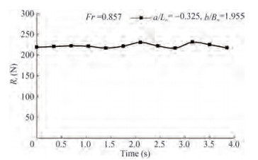 Figure 6 Time history of the total resistance of a/Lm= −0.325, b/Bm= 1.955 at Fr = 0.857
Based on the Froude assumption, the residuary resistance can be derived by subtracting the frictional resistance from the total resistance. Then, the coefficient of the residuary resistance can be obtained. The curves of the aftward trimaran and forward trimaran are shown in Figure 7.
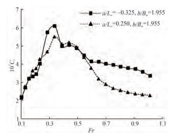 Figure 7 Coefficient of the trimaran residuary resistance
From the curves in Figure 7, a notable phenomenon is observed, in which the aft-ward trimaran produces an unusually high resistance at high speeds (Fr > 0.6). To examine this, the experimental snapshots at Fr = 0.75 of the five configurations for the same transverse distance (b/Bm = 1.955) are shown in Figure 8. As shown in the pictures, the aftward trimaran produces strong splashes. However, the splash gradually decreases if the side hulls are moved forward. The splash even disappears for the middle trimaran and forward trimaran. Generally, a ship moving in calm water produces Kelvin's wave systems. If the side hulls are placed inside Kelvin's wave systems produced by the main hull, a strong splash is produced, which results in an apparent resistance increase. This is the reason why the aft-ward trimaran produces a significantly larger resistance than the forward trimaran at a high Froude number. The relative positions of the different configurations in Kelvin's wave systems of the main hull are shown in Figure 9. Furthermore, the two aft-ward configurations of the small lateral distance (b/Bm = 1.117) produce an obvious splash between the main hull and side hulls. The real Kelvin's wave systems in the experiment are clearly shown in Figure 10.
 Figure 8 Experimental pictures in calm water at Fr=0.75 for Model A
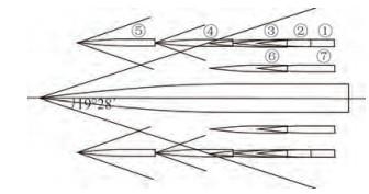 Figure 9 Kelvin's wave systems of trimaran models
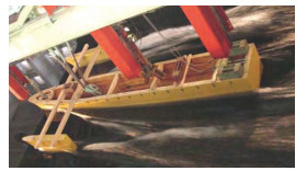 Figure 10 Picture of Kelvin's wave systems in the experiment
To examine if the splash is dependent on sectional forms, two more models were used, which are denoted as Model B and Model C, respectively. The body plans of the two models are shown in Figure 11, and the main particulars are given in Table 3
 Figure 11 Body plans of Model B and Model CTable 3 Main particulars of Model B and Model C
Items Model B Model C Main hull Side hulls Main hull Side hulls Length of waterline (m) 4.763 2.071 4.286 2.142 9 Breadth of waterline (m) 0.458 5 0.110 4 0.247 5 0.041 2 Draft (m) 0.138 9 0.046 9 0.128 6 0.019 6 Displacement (m3) 0.134 5 0.003 5 0.075 7 0.000 54 Wetted Surface (m2) 2.216 0.226 3 1.572 0.096 5 Block coefficient 0.443 0.329 0.458 0.459 Prismatic coefficient 0.627 0.541 0.692 0.787 The same coordinates and variables as shown in Figure 12 are used. The aft-ward trimaran and forward trimaran were designed for the two models, which are given in Table 4. The resistance experiments were also conducted for the two models. In this test, however, a new four-component measuring instrument was used to measure the hydrodynamic performance indices.
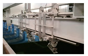 Figure 12 Four-component measuring instrumentTable 4 Configurations of Model B and Model C
Model B Model C a/Lm b/Bm a/Lm b/Bm -0.273 1.505 -0.222 1.818 0.157 1.505 0.100 1.818 The curves of the coefficients are given in Figure 13. Again, large resistance increases are observed for Models B and C at high speeds (Fr > 0.6). This is further verified by the observations from the pictures taken from a test run of Model B, as shown in Figure 14. Splash occurred on the aft-ward trimaran but not on the forward trimaran. The same is true for Model C. This finding strongly indicates that the splash phenomenon is a common phenomenon regardless of trimaran hull forms.
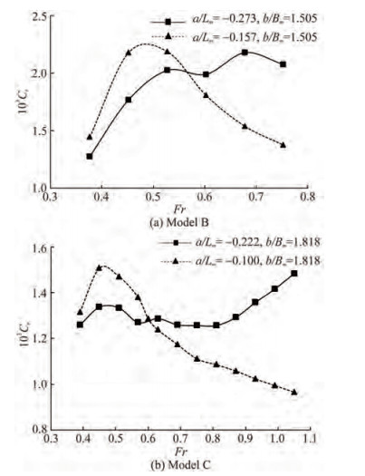 Figure 13 Coefficient of the trimaran residuary resistance of Model B and Model C
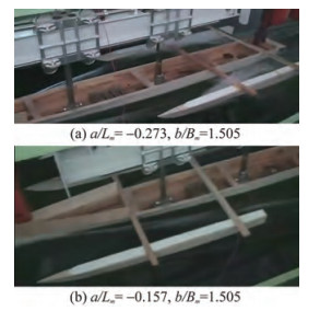 Figure 14 Experimental pictures in calm water at Fr = 0.75 for Model B
The previous analysis also reveals that the forward trimaran is advantageous in resistance performance at high speeds (Fr > 0.6) in calm water, due to its ability to reduce the strong splash between the main hull and side hulls. However, the optimum configuration at the low speed range (Fr < 0.6) may not have a forward trimaran hull form. The optimum configuration depends on speeds. Based on the experimental results of Model A, an optimum configuration spectrum for resistance in calm water was obtained, as shown in Figure 15.
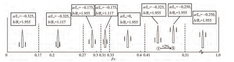 Figure 15 Spectrum of the optimum configuration of resistance in calm water
3.2 Heaving at high frequencies
In Model A, the heave tests were conducted in head regular waves at four typical Froude numbers: Fr = 0, 0.234, 0.494, and 0.701. The heave response amplitude operator (RAO) curves of different configurations at different Froude numbers are given in Figure 16.
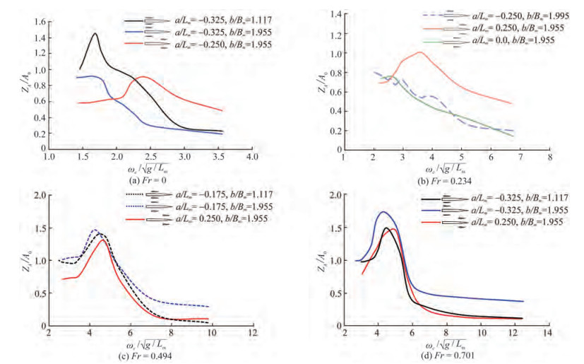 Figure 16 Heaving Response Amplitude Operators (RAOs) of different configurations for Model A
One of the interesting observations in Figure 16 is that the RAO tends to zero very slowly for certain configurations. For example, the forward trimarans in Figure 16(a) and (b) and aft-ward trimarans in Figure 16(c) and (d) exhibit a significant deviation from zero at high frequencies. This result is due to the fact that high-frequency waves, although short in length compared with those of the main hull, are comparative to the length of the side hulls, thus exciting large heaving at high frequencies.
By repeating the tests at different Froude numbers, we obtained the optimum configurations in terms of heaving amplitudes, as given in Figure 17.
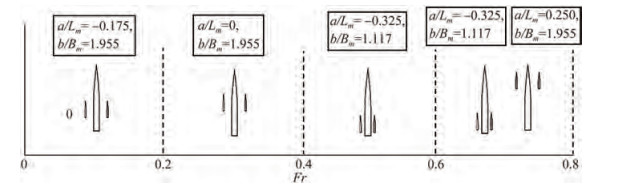 Figure 17 Spectrum of the optimum configuration for heaving in regular waves
3.3 Pitch at low frequencies
The pitch tests were performed in head regular waves at four typical Froude numbers: Fr = 0.0, 0.234, 0.494, and 0.701. The pitch RAO curves for different configurations at different Froude numbers are shown in Figure 18.
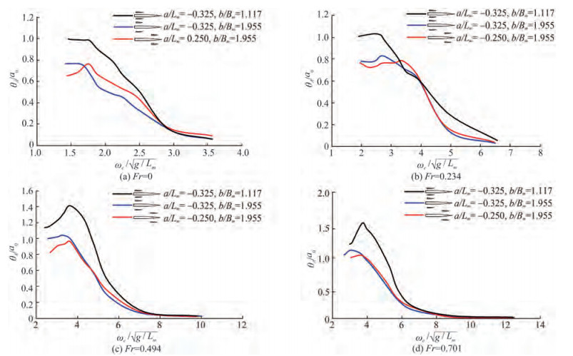 Figure 18 Pitch RAO of different configurations for Model A
Based on the ship motion theory, the pitch RAO of a mono-hulled ship in waves tends to one when the frequency is close to zero. This condition is due to the fact that the smaller the frequency, the longer the waves. If the wave is long enough, the ship will oscillate with the same amplitude as the wave. In other words, the pitch RAO should tend to one when the frequency is close to zero.
However, this case may not be true for trimaran ships. For example, in Figure 18, the pitch RAOs may not tend to one at low frequencies. In Figure 18(a) and 18(b), the red and blue lines tend to 0.8 at low frequencies. In Figure 18(c), the black line tends to 1.2, whereas the red line tends to 0.8. The two small side hulls provide an additional moment to the main hull. The moment lifts the ship up-wards as the ship moves down and pulls the ship down-wards as the ship moves up. The additional moment produced by the side hulls placed either forward or aft-ward acts against ship motions in waves, thus reducing pitch responses.
The comparison of the curves in Figure 18 for different Froude numbers yields a spectrum of the optimum configuration for the pitch response in regular waves, as shown in Figure 19.
 Figure 19 Spectrum of the optimum configuration for pitch in regular waves
3.4 Roll at zero speed
The roll tests were performed in regular waves only at one Froude number of Fr = 0. The roll RAO curves of different configurations at Fr = 0 are shown in Figure 20.
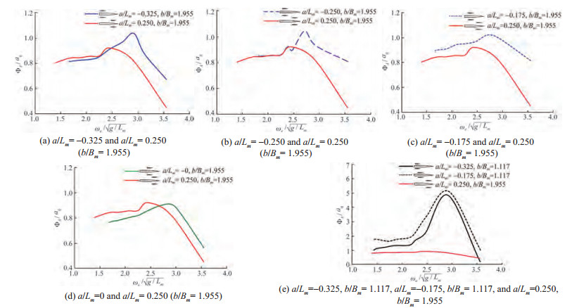 Figure 20 Roll RAO of different configurations for Model A
The roll RAO of all the configurations did not approach 0 at high frequencies. Furthermore, the roll RAO did not approach 1 at low frequencies. At a high frequency, the wavelength is short enough for the length of the main hull but not for the side hulls. Thus, short waves may excite the side hulls to oscillate. This condition explains why the roll RAO does not tend to one at low frequencies and zero at high frequencies (Gong et al. 2021).
Meanwhile, in the figure, red lines (representing the forward trimaran configuration) are greatly lower than the blue lines (representing the aft-ward trimaran configurations), which is an interesting observation. It results from the fact that forward trimaran configurations strengthen the restoring moment at the bow, which is weaker compared with the restoring moment of the aft part of the hull.
3.5 Resistance in regular waves
The resistance for the configurations was also tested in regular waves at three different Froude numbers: Fr = 0.234, 0.494, and 0.701. The test results are plotted in Figure 21. Different from previous results, the forward trimaran configuration is not always the best, as shown in Figure 21(b). In this case, the aft-ward trimaran configuration is better than the forward one. However, the difference is not significant, but the two configurations are close.
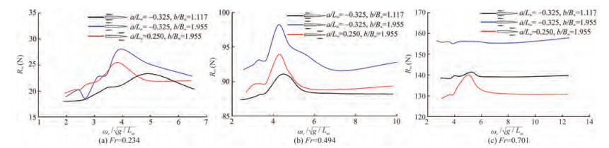 Figure 21 Resistance in waves of different configurations for Model A
The aft-ward configuration of a/Lm= −0.325, b/Bm= 1.117 produced the smallest resistance in waves for Fr = 0.234 and Fr = 0.494. However, for Fr = 0.701, the forward configuration of a/Lm= 0.250, b/Bm= 1.955 produced the smallest resistance. A spectrum of the optimum configuration for the resistance in regular waves was obtained, as shown in Figure 22. The optimum configuration for the roll response at Fr = 0 is also shown in Figure 22.
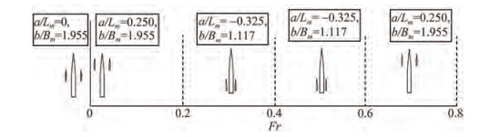 Figure 22 Spectrum of the optimum configuration for the roll and resistance in regular waves
4 Conclusions
Based on the experimental data of a series of trimaran configurations, the following conclusions can be obtained:
1) The study reveals a new resistance component of splash resistance, which is important at high speeds. The forward trimaran configuration may remove the splash resistance. For the forward trimaran, side hulls are not inside Kelvin's wave systems of the main hull, and it can avoid the splash phenomenon between the main hull and side hulls. This finding applies to all the three trimaran models tested in this study. Thus, a new configuration form (forward trimaran) is proposed.
2) The spectrum of optimum configurations for resistance in calm water versus Froude number was experimentally obtained. In addition, the experimentally obtained spectra for motions and resistance in regular waves are given.
3) Shorter waves compared with the main hull may be longer waves to the side hulls, thus exciting the side hulls to oscillate in waves. This case results in complicated behavior at high frequencies. The same is true for long waves. Therefore, sufficient consideration should be given to the arrangements of side hulls based on speed and wave conditions, which is very important at the design stage.
4) In the tests, the wooden beams connecting the three hulls interfered with the splashing. In the model tests, the wooden beams interfered with the splash. In a real ship, wooden beams are replaced with a bridge connecting the main and side hulls. Such an effect would reappear in the real case again. However, specific resistance values may be slightly different in the real and model cases. We will explore this point further in our future works.
Open Access This article is licensed under a Creative Commons Attribution 4.0 International License, which permits use, sharing, adaptation, distribution and reproduction in any medium or format, as long as you give appropriate credit to the original author(s) and thesource, provide a link to the Creative Commons licence, and indicateif changes were made. The images or other third party material in thisarticle are included in the article's Creative Commons licence, unlessindicated otherwise in a credit line to the material. If material is notincluded in the article's Creative Commons licence and your intendeduse is not permitted by statutory regulation or exceeds the permitteduse, you will need to obtain permission directly from the copyrightholder. To view a copy of this licence, visit http:/creativecommons.org/licenses/by/4.0/. -
Figure 1 Body plan of Model A
Figure 2 Trimaran configuration
Figure 3 Wave generator composed of 20 small plates
Figure 4 Apparatus used for Model A
Figure 5 Model tests for Model A in the towing tank
Figure 6 Time history of the total resistance of a/Lm= −0.325, b/Bm= 1.955 at Fr = 0.857
Figure 7 Coefficient of the trimaran residuary resistance
Figure 8 Experimental pictures in calm water at Fr=0.75 for Model A
Figure 9 Kelvin's wave systems of trimaran models
Figure 10 Picture of Kelvin's wave systems in the experiment
Figure 11 Body plans of Model B and Model C
Figure 12 Four-component measuring instrument
Figure 13 Coefficient of the trimaran residuary resistance of Model B and Model C
Figure 14 Experimental pictures in calm water at Fr = 0.75 for Model B
Figure 15 Spectrum of the optimum configuration of resistance in calm water
Figure 16 Heaving Response Amplitude Operators (RAOs) of different configurations for Model A
Figure 17 Spectrum of the optimum configuration for heaving in regular waves
Figure 18 Pitch RAO of different configurations for Model A
Figure 19 Spectrum of the optimum configuration for pitch in regular waves
Figure 20 Roll RAO of different configurations for Model A
Figure 21 Resistance in waves of different configurations for Model A
Figure 22 Spectrum of the optimum configuration for the roll and resistance in regular waves
Table 1 Main particulars of Model A
Items Main hull Side hulls Length of waterline (m) 4.000 1.000 Breadth of waterline (m) 0.358 0.085 Draft (m) 0.170 0.100 Displacement (m3) 0.129 0.004 5 Wetted Surface (m2) 1.899 0.201 Block coefficient 0.530 0.524 Prismatic coefficient 0.769 0.746 Table 2 Configurations of trimaran Model A
No. a/Lm b/Bm Layout ① -0.325 1.955 ② -0.250 1.955 ③ -0.175 1.955 ④ 0.0 1.955 ⑤ 0.250 1.955 ⑥ -0.175 1.117 ⑦ -0.325 1.117 Table 3 Main particulars of Model B and Model C
Items Model B Model C Main hull Side hulls Main hull Side hulls Length of waterline (m) 4.763 2.071 4.286 2.142 9 Breadth of waterline (m) 0.458 5 0.110 4 0.247 5 0.041 2 Draft (m) 0.138 9 0.046 9 0.128 6 0.019 6 Displacement (m3) 0.134 5 0.003 5 0.075 7 0.000 54 Wetted Surface (m2) 2.216 0.226 3 1.572 0.096 5 Block coefficient 0.443 0.329 0.458 0.459 Prismatic coefficient 0.627 0.541 0.692 0.787 Table 4 Configurations of Model B and Model C
Model B Model C a/Lm b/Bm a/Lm b/Bm -0.273 1.505 -0.222 1.818 0.157 1.505 0.100 1.818 -
Andrews DJ, Zhang JW (1995) Trimaran ships: The configuration for the frigate of the future. Naval Engineers Journal 107(3): 77-84. DOI: 10.1111/j.1559-3584.1995.tb03038.x Ackers BB, Thad JM, Tredennick OW, Landen CH, Miller EJ, Sodowsky JP, Hadler JB (1997) An investigation of the resistance characteristics of powered trimaran side-hull configurations. SNAME Transactions 105: 349-373 Dogrul A, Yildiz B (2022) Numerical prediction of form factor and wave interference of a trimaran for different outrigger positions. China Ocean Engineering 36: 279-288. DOI: 10.1007/s13344-022-0024-9 Gong JY, Li YB, Cui M, Fu Z, Hong ZC (2021) The effect of side-hull position on the seakeeping performance of a trimaran at various headings. Ocean Engineering 239: 1-18. DOI: 10.1016/j.oceaneng.2021.109897 Hebblewhite K, Sahoo PK, Doctors LJ (2007) A case study: theoretical and experimental analysis of motion characteristics of a trimaran hull form. Ship and Offshore Structures 2(2): 149-156. DOI: 10.1080/17445300701430242 Khoob AA, Feizi A, Mohamadi A, Vakilabadi KA, Fazeliniai A, Moghaddampour S (2021) An experimental study on the effect of the side hull symmetry on the resistance performance of a wave-piercing Trimaran. Journal of Marine Science and Application 20(3): 456-466. DOI: 10.1007/s11804-021-00214-1 Liu JY, Duan WY, Liao KP (2021) Numerical simulations of trimaran motion in regular waves with different outrigger layouts. Journal of Hydrodynamics, Ser. A 36(6): 772-780. (in Chinese) DOI: 10.16076/j.cnki.cjhd.2021.06.003 Lv HZ, Wei CZ, Liang XF, Yi H (2022) Optimisation of wave-piercing trimaran outrigger layout with comprehensive consideration of resistance and seakeeping. Ocean Engineering 250: 1-16. DOI: 10.1016/j.oceaneng.2022.111050 Naval Technology (2001) Citing electronic sources of information. Triton Trimaran. Available from https://www.naval-technology.com/projects/trimaran/ Poundra GAP, Utama IKAP, Hardianto D, Suwasono B (2017) Optimizing trimaran yacht hull configuration based on resistance and seakeeping criteria. Procedia Engineering 194: 112-119. DOI: 10.1016/j.proeng.2017.08.124 Ship Technology (2006) Citing electronic sources of information. Benchijigua Express—Trimaran Vehicle/Passenger. Available from https://www.ship-technology.com/projects/Benchijigua/ Wang SM, Duan WY, Xu QL, Duan F, Deng GZ, Li Y (2021) Study on fast interference wave resistance optimization method for trimaran outrigger layout. Ocean Engineering 232: 1-10. DOI: 10.1016/j.oceaneng.2021.109104 Wang Z, Lu XP, Fu P (2009) Research on the effect of the side hull position on the wave making resistance characteristics of the trimaran. Shipbuilding of China 50(2): 31-39. (in Chinese) Xu M, Zhang SL (2011) A numerical study on side hull optimization for trimaran. Journal of Hydrodynamics, Ser. B 23(2): 265-272. DOI: 10.1016/S1001-6058(10)60112-6 Yildiz B, Sener B, Duman S, Datla R (2020) A numerical and experimental study on the outrigger positioning of a trimaran hull in terms of resistance. Ocean Engineering 198: 1-12. DOI: 10.1016/j.oceaneng.2020.106938 Zhou GL, Ai ZT, Deng R, Huang DB, Liu GJ (2015) Resistance research of alterative layouts of trimaran based on CFD. Ship Enigineering 37(1): 27-30. (in Chinese) DOI: 10.13788/j.cnki.cbgc.2015.01.027