-
Abstract
In the shipbuilding industry, market competition is currently operating in an intense state. To be able to strive in the global market, the shipbuilders must able to produce ships that are more efficient and can be constructed in a relatively short amount of time. The piping layouts in the engine room requires a lot of time for the designer to design the best possible route and in a way are not the most efficient route. This paper presents an automatic piping support system in the ship's engine room based on the Dijkstra's algorithm of pathfinding method. The proposed method is focused on finding the shortest possible route with a consideration of the following things: cost of the bend pipe, cost of the crossing pipe, cost reduction by pipe support, restriction on piping, reduction of calculation time, and design procedure of piping route. Dijkstra's shortest path algorithm is adopted to find the shortest path route between the start and goal point that is determined based on the layout of the ship's engine room. Genetic algorithm is adopted to decide the sequence of the pipe execution. The details of the proposed method are explained in this paper. This paper also discusses the application of the proposed method on an actual ship and evaluates its effectiveness.-
Keywords:
- Design optimization ·
- Piping system ·
- Dijkstra's algorithm ·
- Shortest path
Article Highlights• An automatic piping support system in the ship engine room is presented based on the Dijkstra's algorithm of pathfinding method;• Dijkstra's shortest path algorithm is adopted to find the shortest path route between the start and goal point, and a genetic algorithm is adopted to decide the sequence of the pipe execution;• The proposed method is applied to an actual ship, verifying its effectiveness based on the piping cost, pipe dimensions, and shortest path direction of movement with crossing and bending as a consideration. -
1 Introduction
Since the 1970s, the piping route design has been studied in various industrial fields such as ship industry, aerospace industry, and many other industries. The design of the piping system inside the ship's engine room is a complex process with a lot of constraints. The piping route design process is a very time-consuming process and very difficult to get a feasible and most effective and efficient design. Systematic studies in terms of route planning have been studied by researchers around the globe. Dijkstra algorithm (Dijkstra, 1959) was proposed in 1959, which is a very well-known algorithm for pathfinding optimization to find the shortest path possible. In the past few years, researchers on the piping route planning used modern optimization methods such as genetic algorithm (Sandurkar and Chen, 1999; Kanemoto et al., 2004; Ren et al., 2013; Wang et al., 2006; Sui and Niu, 2016; Ikehira, et al., 2005; Dong and Lin, et al., 2017b; Ito, 1999; Kim et al., 1996; Zhou, 2017), ant colony algorithm (Jiang et al., 2015; Christodoulou and Ellinas, 2010; Wu et al., 2019; Qu et al., 2016; Wang et al., 2018; Fan et al., 2016), and particle swarm algorithm (Dong and Lin, 2017a; Liu and Wang, 2011; Liu and Wang, 2008) to get the most optimized route. Dong and Lin (2017b) use genetic algorithm and cooperative coevolution method to optimize the pipe routing inside the ship. Wang et al.. (2018) and Fan et al.. (2006) optimize the ship pipe routing by using different approach which is ant colony algorithm. Ando and Kimura (2012) successfully developed automatic piping route algorithm with a consideration of bending and elbows that based on Dijkstra algorithm. Pipe routing design, which is related to other tasks, is one of the most important processes at the detailed design stage of a ship (Niu et al., 2016).
Nowadays, the optimization algorithm for pathfinding method mainly focused on the case with two terminals. Park and Storch (2002) successfully developed a cell-generation method for pipe routing in a ship engine room that consider the branch pipeline as a compound of two simple forms: end-forked and middle-forked. Kang and Lee (2017) use the least cost path algorithm and laplacian smoothing for optimization of the pipeline route. Unfortunately, the researchers rarely use the pipe diameter as a consideration for the pathfinding method. The piping cost vary based on the pipe diameter in term of the cost of production, bending, and crossing of the pipe. From the statement above, the differences in the pipe diameter should be taken into consideration in the optimization algorithm because different pipe diameter has a different piping cost. Based on the differences of the piping cost, the concept of sorting which pipe that goes first to minimize the piping cost is also taken into consideration. Method to sort which pipe goes first is by using a genetic algorithm. In this paper, we used Dijkstra's algorithm with some improvements added. Dijkstra's algorithm most likely gives the best solution and this algorithm is easy to study and apply in various types of problems. By adding some improvements to the method, the results are always the shortest pipe route that has a minimum number of bending and crossing.
2 Methods and experiments
Characteristics of the influence of pipe length, bending, crossing, pipe diameter and the amount of support are translated into cost and penalty. Costs and penalties added to each other in a system form the value of piping costs. The objective function is the main concern in this optimization process, which is to minimize piping costs by avoiding various aspects of penalties. The piping cost itself is a modelling of the actual cost of the pipeline to facilitate and speed up the optimization process. To meet these objectives, the design variable used is the piping route system. Because this optimization process produces visual output, the main variable that is optimized is the design variable. The design variable used is a visual representation of the piping route system.
The process needs to be synchronized with the consideration of the length of execution time. Consequently, the ship deck and piping route must be modelled as a two-dimensional design. In the deck design, there can be known various information including the location of the access path, general constraints and special constraints. While in the pipe system data the pipe diameter size is known along with the start point and goal point information. There are three constraints that become the reference in the case of optimizing this pipe route. First, as stated earlier that the movement of the pipeline is limited to a two-dimensional plane. Second, pipes are only allowed to move horizontally and vertically. Third, the pipe route is only allowed to turn to avoid obstacles with a turning angle of 90 degrees.
2.1 Total scheme of the methods
As can be seen from the flow diagram shown in figure 2, in this overall optimization, it takes four input data with two main processes that will produce two output data. The main process that must first be carried out is to optimize the design procedure using Genetic Algorithms, so that the best pipeline data is generated which pipe should be optimized first. The data is used in conjunction with data decks, pipe data, penalty data and flange data for optimization using the Dijkstra Algorithm. This is the main optimization process, which also considers the type of pipe, the cost of bending penalties, the cost of crossing penalties, the cost reduction by sharing the same pipe support, and the time reduction. The data generated is optimized pipeline data in the form of images of each pipe name and the pipe route cost.
Table 1 Comparison with the previous studyConsideration Ren et al. (2013) Wang et al. (2018) Dong et al. (2017) Ito (1999) Kim et al. (1996) Ando et al. (2012) Park et al. This Paper (2002) Shortest path √ √ √ √ √ √ √ √ Minimum bending √ √ √ × × √ √ √ Minimum crossing √ Not Allowed × × × × × √ Avoid obstacles √ × √ √ √ √ √ √ Cost reduction by pipe support × × √ × × × √ √ Restriction on piping × × × × × × × √ Reduction of calculation time × × × × × √ × √ Design procedure of piping route (using genetic algorithm) × × × × × × × √ 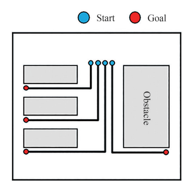 Figure 1 Illustration of problem definition
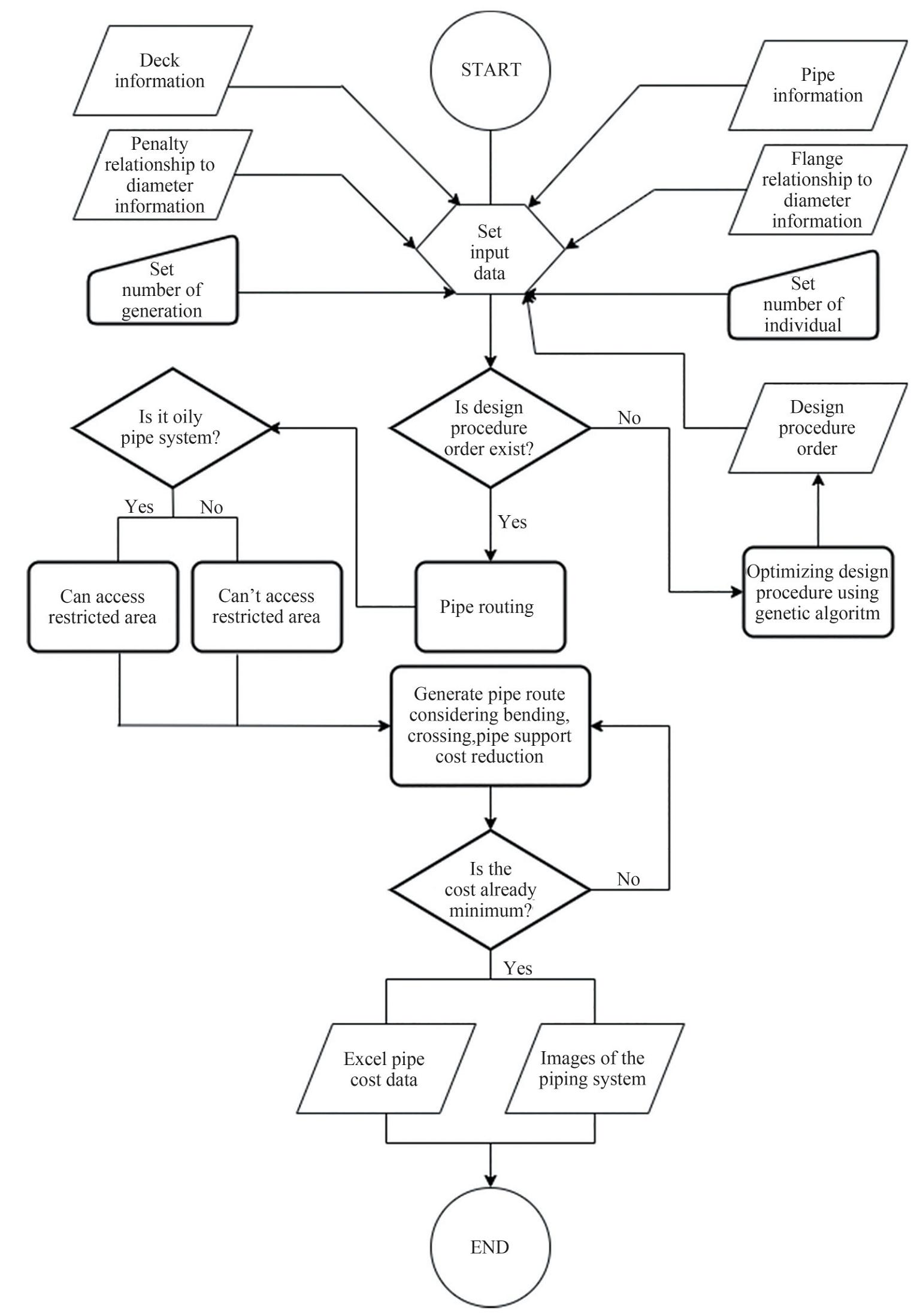 Figure 2 Overall method flow diagram
2.2 Dijkstra's algorithm
Dijkstra's algorithm is arguably the most famous and efficient pathfinding algorithm which is an algorithm for finding the shortest path between nodes in a graph. It was founded in 1956 by a computer scientist named Edsger W. Dijkstra and published three years after its founding. This method considers all the vertexes for a given origin node and finds the shortest path between the given origin node and all the other vertex. Dijkstra's algorithm is used in many practices such as route finder application and game algorithm, one of which are provided from previous research (Ajiwaskita et al., 2020) as an improvement of the previous research that the method only attributes the belonging of pipe bending and crossing and with one type of fluid, whereas this research using multiple constraint to develop the most optimum piping design. Also its started to progresses in a way of a jump point search for investigating the shortest path (Min et al., 2020). Dijkstra's algorithm always gives the best solution that exists. As similar as the other method, Dijkstra's algorithm only considers finding the shortest path available without considers other aspects such as bending and crossing of pipe. To solve the problem, there are some constraints added to Dijkstra's algorithm to give a better result. The constraints added to the algorithm are explained one by one in the subsections below.
2.3 Genetic algorithm
Genetic Algorithms are an optimization technique that was initiated by Darwin's theory of evolution through genetic selection. The theory and applicability of Genetic Algorithms were heavily influenced by Holland (1975) in consideration to be the pioneer. A GA uses a highly abstract version of evolutionary processes to evolve solutions to given problems (McCall, 2005). In Genetic Algorithm there are chromosome and population, every chromosome represents a solution to a given problem and population is a set of chromosomes. There is fitness value in a genetic algorithm that measures how good the solution is for its problem. Genetic algorithm uses a fitness-based selection and recombination to produce a successor population (McCall, 2005). During the recombination process, the chromosomes from the parent are selected and their genetic material is recombined to produce child chromosomes (McCall, 2005). The transition of one generation to the next consist of the following process: selection, crossover, mutation, and sampling (Bodenhofer, 1999). The fitness value of the chromosome tends to increase throughout the generations.
2.4 Constraint
For the program can choose the most optimal path for each pipe, we need to input every essential constraint that is connected to the real situation. Each constraint will give restriction for the running program to avoid mistakes in the design. The constraints that are needed for this pipe routing are the cost of bending pipe, the cost of crossing pipe, and cost reduction pipe support. These three are the restrictions that must be fulfilled to achieve the most optimal path.
2.4.1 Cost of bending pipe
When a pipe route has a bending on them it will cost a lot of money. In our algorithm, cost per 1 meter of pipe length we consider as 1 and every bending cost 1.
From the picture above we can see that the pipe length of both A and B are the same with a value of 10 meters. But cost-wise the cost of A will be higher because it has 2 bending that makes the piping cost is 12. The cost of B is lower because it only has 1 bending that makes the piping cost only 11. The pipe route of B is more desirable because the cost is lower than A and the number of bending is lower. Therefore, we adjust the program to find the lowest cost of piping with the lowest bending possible.
We try to explain how the bending cost modelling fall into place. From figure 4, there are differences from the general network and change network. The value of every black edge is 1. For the general network, the bending cost of the pipe is not calculated. The change network model shows how the bending cost is calculated. The red edges display the condition when the pipe changes its direction, and the blue edges display the condition when the pipe stays in the same direction. The red edges value is 1 and the value of the blue edge is 0. Therefore, if there are bending that happened, it will add another value of 1 for the bending. If the pipes are on a straight line, it will have no value to be added as we have seen in figure 4.
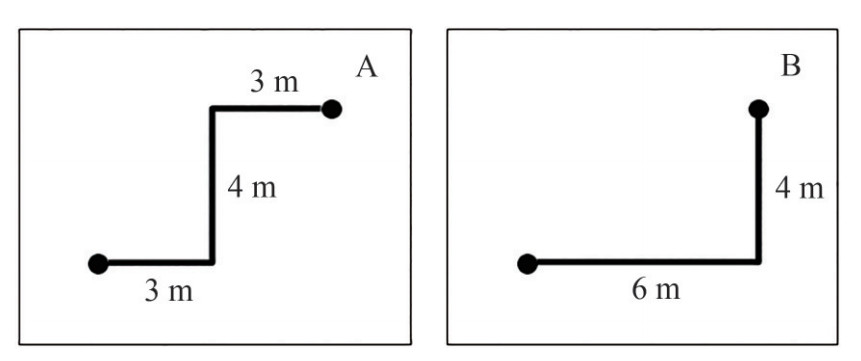 Figure 3 Bending on pipe route
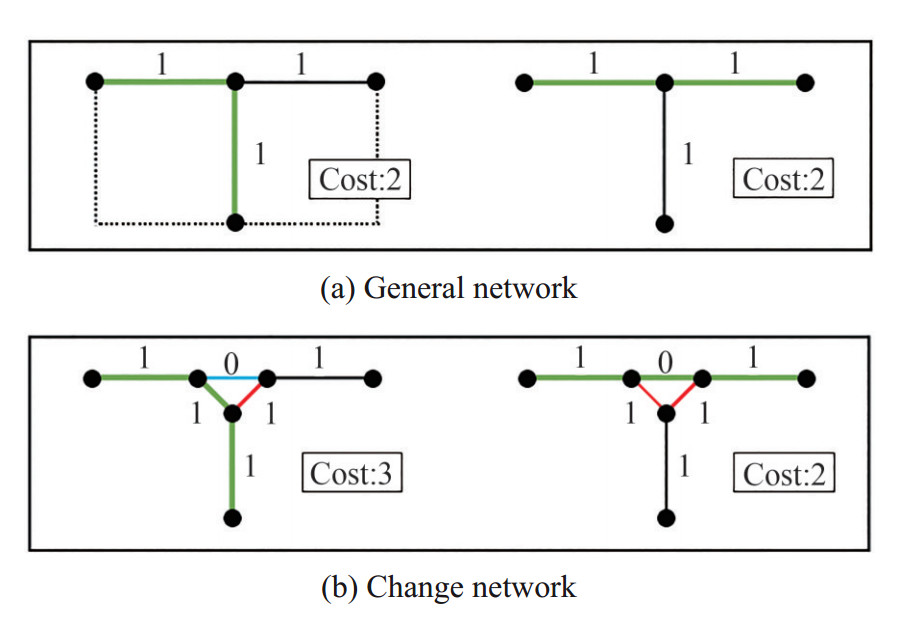 Figure 4 Penalty scheme for bending
2.4.2 Cost of crossing pipe
It also cost a lot of money to have a pipe route that crosses another pipe. In our algorithm, for every 1 meter of pipe length, the cost for the normal route is 1 and for a pipe that crosses another pipe is 4.
From the pictures above, we can see that the pipe length of both figure 5(a) and figure 5(b) are the same with a value of 11 meters with pre-designed piping as a constraint. Figure 5(a) has less efficiency and higher cost because this route designed to cross the pre-designed piping, for a crossing, we added 5 points as penalty cost. Figure 5(b) has lower cost and higher efficiency because this route designed to not cross to another pipe. The pipe route of figure 5(b) is more desirable because the cost is lower than figure 5(a) with a lower number of the crossing. Therefore, we adjust the program to find the lowest cost of piping with the lowest crossing possible.
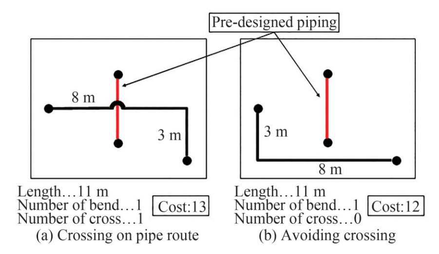 Figure 5 Cost of crossing pipe
We try to explain how the crossing cost modeling falls into place. From the figure above, there are differences from the pre-designed piping as shown in figure 6(a) and calculated pipe routed as shown in figure 6(b). The value of every black edge is 1. For the figure 6(a), the bending and crossing cost of the pipe is not calculated. The change network models show how the crossing cost is calculated. The black line is capable of being chosen as pipe route and the grey line is the pre-designed piping. Therefore, when the pipe routed to cross the grey line, it will have another value of 4 for the crossing, but if there is no grey line as the pre-designed pipe, it will have no value to be added.
 Figure 6 Crossing modelling
2.4.3 Cost reduction pipe support
Pipe support is something that used as the foothold for the piping. The number of pipe support is reduced by making multiple pipes into one bundle. Therefore, it can lower the piping cost because it will only need one pipe support for multiple pipes.
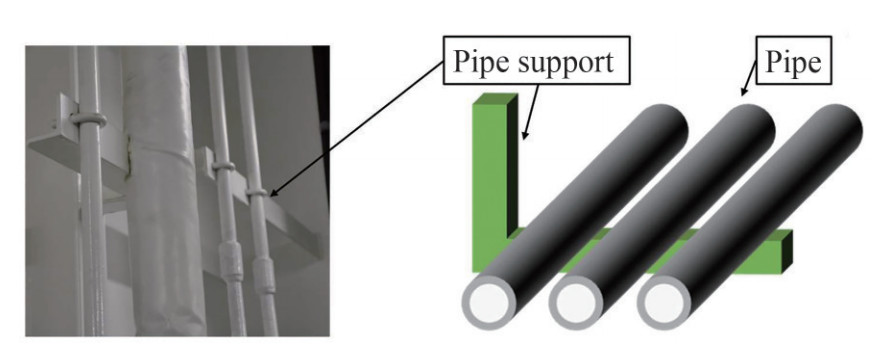 Figure 7 Pipe support scheme
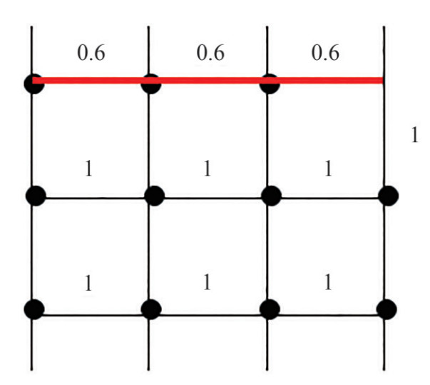 Figure 8 Cost reduction by sharing the same pipe support
From the figure above, we can see that the value of pipe that ran through the black edges is 1 and the red edges are 0.6. The red edges are the pipe route that has been installed with pipe support. The black edges are the route that has not been utilized and have not been installed with pipe support. Therefore, the value of the red edges is lower than the black edges.
The different values of the cost of models A and B from the figure above can be seen. The piping cost of model A in figure 9 is lower because this route utilizes the red edges that already have pipe support on it. Model B has a higher piping cost because it utilizes black edges. Therefore, the shipbuilder must make new pipe supports for the pipe that utilizes the black edges.
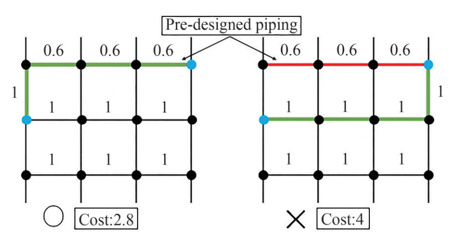 Figure 9 Cost reduction by sharing the same pipe support's scheme
2.4.4 Restriction
For this type of constraint, there is a restriction for its application. Each pipe existing on the edge has a diameter. When a pipe passes through the same edge, the new pipe diameter will be added to the calculation of the total diameter of the pipe existing on the edges. For each support, there is always a maximum diameter that it can hold. This value is known as a reference value. This value comes from the strength of the pipe support. This means that the reference value is the maximum load that the pipe support can hold. So, if there is a pipe that wants to pass an edge that is already full of another pipe, that pipe cannot be passed anymore on that same edge. It's because the pipe support cannot withstand another load if it exceeds the reference value. That's the restriction for cost reduction with consideration of pipe support.
2.5 Categorizing the pipe
We categorize the pipe into two kinds of groups. The first group is the general pipe, and the second group is the fuel oil pipe. The difference between these two kinds of pipes is the fuel pipe cannot use the restricted area as one of the paths for the pathfinding algorithm. So, for the fuel oil pipe, it must find another route to avoid the restricted area. The general pipe still can use the restricted area in the pathfinding algorithm. This is due to the temperature of the area, to improve safety and reduce any risk of fire and explosion.
2.6 Reduction of calculation time
In conventional ways, we used grids as a dimensional parameter for 2-dimensional automatic pipe routing program. But unfortunately, it cost a big amount of Random Access Memory (RAM) capacity. Conventional pipe routing design using a grid system that slows the program's performance. It's because this kind of approach makes the program process many unnecessary data for each running loop. To anticipate these loses and to reduce the calculation time, network sparse created with only created grids around the obstacles, start and goal points. We used something like mesh simplification algorithm for this method. Many different approaches for this kind of method have been developed to improve program efficiency, such as reduction of calculation time (Cignoni et al., 1998). This way, the program can focus to load only the necessary amount of info regarding the route that the pipe chooses. The reason that three points are chosen is that the line from those points is the only thing that matters. Those points can only choose their way either vertical or horizontal. That is why only the lines that connected to the point will be generated by the system. The practicality of this method has been researched in many instances. The result from that research shows that this method is a good choice for the improvement of the program (Wünsche, 1998). With this method, we can greatly reduce our calculation time.
2.7 Consideration of design procedure
Production cost, bending cost, and crossing cost vary depending on the pipe diameter. Piping cost varies greatly depending on the design procedure. Even with the same data but with different design can produce an entirely different result.
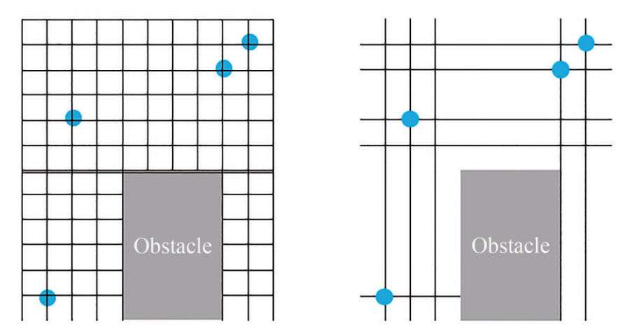 Figure 10 Grid reduction comparison
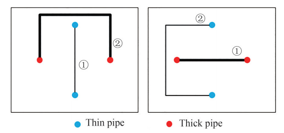 Figure 11 Design procedure considerations
The left one the design procedure starts with the thin pipe and ended with the thick pipe. The right one the design procedure starts with the thick pipe and ended with the thin pipe. For the first model, the design procedure should start from the thickest to the thinnest pipe so that the thick pipe will have a shorter length with the best possible route available. But, in practice, this kind of approach cannot give the best result. So, for the design procedure, we implemented an optimization method by using a genetic algorithm (GA) to find the best design procedure to minimize the piping cost.
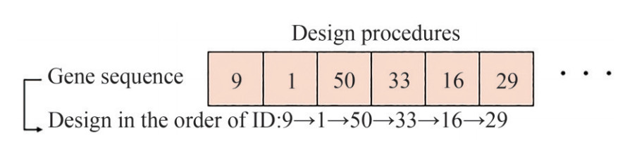 Figure 12 Recording using genetic algorithm
3 Results
3.1 Problem definition
There are four conditions to consider in this study, the following optimizations were performed: Case 1: Actual pipe route. Case 2: Optimized pipe route with thick to thin design procedure. Case 3: Optimized pipe route with the GA design procedure.
3.2 Input Data
3.3 Optimization result
Dijkstra algorithm was adopted to optimize the piping system in a 2D engine room. All the machinery simulated as obstacles using simplification. it is assumed that the engine room is an area consisting of a set of grids of size 80×48. A grid measuring 400 millimeters on an actual ship. This result is exported as an excel file with the support of C# program as depicted in Figure 13. By creating grids only at the obstacles, start and finish points, we managed to run this program only in 5.1 seconds. If we adjust the program to executive all the grids available, the program needs 15 minutes to finish all the execution.
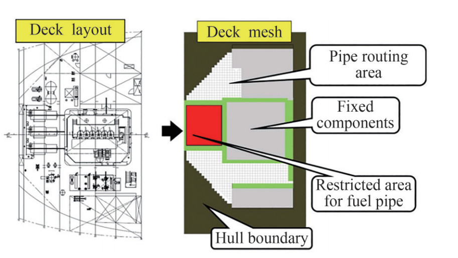 Figure 13 Deck information
 Figure 14 Pipe route of actual ship
The optimization results from case 2 and case 3 is different because of the sequence of the pipe execution. Although the pipe information input is the same, the different sequence of the pipe execution changes the pipe route. On the pipe route picture of case 2 and case 3. The differences colour in pipe route line explains the diameter of the pipe on the pipe support. The black pipeline means the total diameter is less than 400 mm, the blue pipeline means the total diameter is less than 800 mm, and the gold line means the total diameter is less than 1 200 mm.
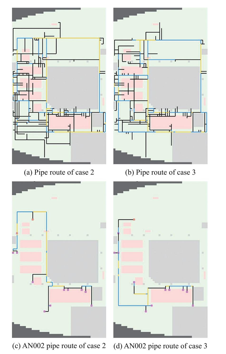 Figure 15 Optimization results
3.4 Cost comparison
Table 2 contains the cost comparison of cases 1-3. We took pipe length, number of bending, number of crossing, and total cost (objective function) as data for this comparison. As shown by table 2, using the pipe length as parameter, case 1 before optimization has the shortest route. But, using the number of bending parameters, case 2 is the most optimal, 5.58% better than the current number of bending. Meanwhile, using the number of crossings as parameter, case 2 is also the most optimal, 57.39% better than the current number of crossings. To find out the effect of genetic algorithms on total cost, we have compared case 3 with case 2 which results in a decrease in the value of total cost of 5.59%. Case 2, in total, is 13.25% more efficient than actual ship route
Table 2 Problem settingDesign Variables Piping Route Dimensions Piping routes move in 2-dimensional plane Constraints The direction of movement of the route is vertical and horizontal only Objective Functions The turn angle of the route is only 90 degrees, minimizing piping cost Table 3 Case descriptionsCase 1 Case 2 Case 3 Total cost (%) 100 105.93 86.75 Pipe length (%) 100 117.15 107.04 Bending (%) 100 103.55 94.42 Crossing (%) 100 84.35 42.61 4 Analysis and discusion
This paper has three important things to consider include pipe length, bending, crossing. Briefly, case 1 is the best result because it has the shortest pipe length whereas cases 2 and 3 provide a longer pipe length. The best result for the optimization of the pipeline route should not only consider the minimum length of the pipe, but there are also two more aspects that need to be considered, which is minimizing the number of bending and crossing. The methodology of this paper considers the penalty of crossing is four times greater than bending. Therefore, although case 1 before optimization has the shortest pipe length, after the optimization, case 2 provides the most optimal results with less bending and crossing of all cases.
5 Conclusion
This study presents a development of pipe routing program on ship machinery room considering bending, crossing, pipe support, time and design procedure using a Dijkstra algorithm. The target of this study is to find the most low-cost pipe route with a minimum number of bending and crossing and maximizing the use of pipe support. From the result based on reference, the Dijkstra algorithm and genetic algorithm proved to be suitable, useful and give a good solution for this kind of problem.
The following conclusion that can be inferred from this study is (1) Optimized design procedure by using genetic algorithm give more advantage by reducing 5.59% total cost compared to thin to thick pipe total cost; (2) The best result for low-cost pipe routing obtained by considering bending, crossing, pipe support, time and design procedure using a genetic algorithm, which is 5.58% more efficient than the actual pipe route in bending, 57.39% more efficient than actual pipe route in crossing, and 13.25% more efficient than actual pipe route in total.
-
Figure 1 Illustration of problem definition
Figure 2 Overall method flow diagram
Figure 3 Bending on pipe route
Figure 4 Penalty scheme for bending
Figure 5 Cost of crossing pipe
Figure 6 Crossing modelling
Figure 7 Pipe support scheme
Figure 8 Cost reduction by sharing the same pipe support
Figure 9 Cost reduction by sharing the same pipe support's scheme
Figure 10 Grid reduction comparison
Figure 11 Design procedure considerations
Figure 12 Recording using genetic algorithm
Figure 13 Deck information
Figure 14 Pipe route of actual ship
Figure 15 Optimization results
Table 1 Comparison with the previous study
Consideration Ren et al. (2013) Wang et al. (2018) Dong et al. (2017) Ito (1999) Kim et al. (1996) Ando et al. (2012) Park et al. This Paper (2002) Shortest path √ √ √ √ √ √ √ √ Minimum bending √ √ √ × × √ √ √ Minimum crossing √ Not Allowed × × × × × √ Avoid obstacles √ × √ √ √ √ √ √ Cost reduction by pipe support × × √ × × × √ √ Restriction on piping × × × × × × × √ Reduction of calculation time × × × × × √ × √ Design procedure of piping route (using genetic algorithm) × × × × × × × √ Table 2 Problem setting
Design Variables Piping Route Dimensions Piping routes move in 2-dimensional plane Constraints The direction of movement of the route is vertical and horizontal only Objective Functions The turn angle of the route is only 90 degrees, minimizing piping cost Table 3 Case descriptions
Case 1 Case 2 Case 3 Total cost (%) 100 105.93 86.75 Pipe length (%) 100 117.15 107.04 Bending (%) 100 103.55 94.42 Crossing (%) 100 84.35 42.61 -
Ajiwaskita F, Gunawan, Yanuar (2020) Pipe-routing optimization using system engineering methodology in ship engine room. Recent Progress on: Mechanical, Infrastructure and Industrial Engineering. Proceedings of International Symposium on Advances in Mechanical Engineering (ISAME): Quality in Research 2019. https://doi.org/10.1063/5.0001001 Ando Y, Kimura H (2012) An automatic piping algorithm including elbows and bends. Journal of the Japan Society of Naval Architects and Ocean Engineers 15(0): 219-226. https://doi.org/10.2534/jjasnaoe.15.219 Bodenhofer U (1999) Genetic Algorithms: Theory and Applications. Christodoulou S, Ellinas G (2010) Pipe routing through ant colony optimization. Journal of Infrastructure Systems 16(2): 149-159. https://doi.org/10.1061/(asce)1076-0342(2010)16:2(149) Cignoni P, Montani C, Scopigno R (1998) A comparison of mesh simplification algorithms. Computers & Graphics 22(1): 37-54. https://doi.org/10.1016/s0097-8493(97)00082-4 Dijkstra E (1959) A note on two problems in connexion with graphs. Numerische Mathematik, 1(1): 269-271. https://doi.org/10.1007/bf01386390 Dong Z, Lin Y (2017a) A particle swarm optimization based approach for ship pipe route design. International Shipbuilding Progress 63(1-2): 59-84. https://doi.org/10.3233/isp-160123 Dong Z, Lin Y (2017b) Ship pipe routing method based on genetic algorithm and cooperative coevolution. Journal of Ship Production and Design 33(2): 122-134. https://doi.org/10.5957/jspd.33.2.150005 Fan Xiaoning, Lin Yan, Ji Zhuoshang (2006) The ant colony optimization for ship pipe route design in 3D space. 2006 6th World Congress on Intelligent Control and Automation. https://doi.org/10.1109/wcica.2006.1712938 Holland J (1975) Adaptation in Natural and Artificial Systems. Cambridge, Mass: MIT Press, 317-333 Ikehira S, Kimura H, Ikezaki E, Kajiwara H (2005) Automatic design for pipe arrangement using multi-objective genetic algorithms. Journal of the Japan Society of Naval Architects and Ocean Engineers 2(0): 155-160. https://doi.org/10.2534/jjasnaoe.2.155 Ito T (1999) A genetic algorithm approach to piping route path planning. Journal of Intelligent Manufacturing, 10(1): 103-114. https://doi.org/10.1023/a:1008924832167 Jiang W, Lin Y, Chen M, Yu Y (2015) A co-evolutionary improved multi-ant colony optimization for ship multiple and branch pipe route design. Ocean Engineering 102: 6 3-70. https://doi.org/10.1016/j.oceaneng.2015.04.028 Kanemoto Y, Sugawara R, Ohmura M (2004) A genetic algorithm for the rectilinear Steiner tree in 3-D VLSI layout design. The 2004 47Th Midwest Symposium on Circuits and Systems 2004. MWSCAS'04. https://doi.org/10.1109/mwscas.2004.1354028 Kang J, Lee B (2017) Optimisation of pipeline route in the presence of obstacles based on a least cost path algorithm and Laplacian smoothing. International Journal of Naval Architecture and Ocean Engineering 9(5): 492-498. https://doi.org/10.1016/j.ijnaoe.2017.02.001 Kim D, Corne D, Ross P (1996) Industrial plant pipe-route optimisation with genetic algorithms. Parallel Problem Solving From Nature — PPSN IV, 1012-1021. https://doi.org/10.1007/3-540-61723-x_1064 Liu Q, Wang C (2008) A modified particle swarm optimizer for pipe route design. 2008 11th IEEE International Conference on Computational Science and Engineering - Workshops. https://doi.org/10.1109/csew.2008.29 Liu Q, Wang C (2011) A discrete particle swarm optimization algorithm for rectilinear branch pipe routing. Assembly Automation 31(4): 363-368. https://doi.org/10.1108/01445151111172952 McCall J (2005) Genetic algorithms for modelling and optimisation. Journal Of Computational and Applied Mathematics 184(1): 205-222. https://doi.org/10.1016/j.cam.2004.07.034 Min J, Ruy W, Park C (2020) Faster pipe auto-routing using improved jump point search. International Journal of Naval Architecture and Ocean Engineering (12): 596-604. https://doi.org/10.1016/j.ijnaoe.2020.07.004 Niu W, Sui H, Niu Y, Cai K, Gao W (2016) Ship pipe routing design using NSGA-Ⅱ and coevolutionary algorithm. Mathematical Problems in Engineering 1-21. https://doi.org/10.1155/2016/7912863 Park J, Storch R (2002) Pipe-routing algorithm development: case study of a ship engine room design. Expert Systems with Applications, 23(3): 299-309. https://doi.org/10.1016/s0957-4174(02)00049-0 Qu Y, Jiang D, Gao G, Huo Y (2016) Pipe routing approach for aircraft engines based on ant colony optimization. Journal of Aerospace Engineering 29(3): 04015057. https://doi.org/10.1061/(asce)as.1943-5525.0000543 Ren T, Zhu Z, Dimirovski G, Gao Z, Sun X, Yu H (2013) A new pipe routing method for aero-engines based on genetic algorithm. Proceedings of the Institution of Mechanical Engineers, Part G: Journal of Aerospace Engineering 228(3): 424-434. https://doi.org/10.1177/0954410012474134 Sandurkar S, Chen W (1999) GAPRUS—genetic algorithms based pipe routing using tessellated objects. Computers In Industry 38(3): 209-223. https://doi.org/10.1016/s0166-3615(98)00130-4 Sui H, Niu W (2016) Branch-pipe-routing approach for ships using improved genetic algorithm. Frontiers of Mechanical Engineering 11(3): 316-323. https://doi.org/10.1007/s11465-016-0384-z Wang H, Zhao C, Yan W, Feng X (2006) Three-dimensional multi-pipe route optimization based on genetic algorithms. IFIP International Federation for Information Processing, 177-183. https://doi.org/10.1007/0-387-34403-9_23 Wang Y, Yu Y, Li K, Zhao X, Guan G (2018) A human-computer cooperation improved ant colony optimization for ship pipe route design. Ocean Engineering 150: 12-20. https://doi.org/10.1016/j.oceaneng.2017.12.024 Wu L, Tian X, Wang H, Liu Q, Xiao W (2019) Improved ant colony optimization algorithm and its application to solve pipe routing design. Assembly Automation 39(1): 45-57. https://doi.org/10.1108/aa-02-2018-022 Wünsche B (1998) A Survey and Evaluation of Mesh Reduction Techniques Zhou J, Liang G, Deng T, Gong J (2017) Route optimization of pipeline in gas-liquid two-phase flow based on genetic algorithm. International Journal of Chemical Engineering 2017: 1-9. https://doi.org/10.1155/2017/1640303
| Citation: |
Gunawan, Kunihiro Hamada, Kakeru Kunihiro, Allessandro Setyo Anggito Utomo, Michael Ahli, Raymond Lesmana, Cornelius, Yutaka Kobayashi, Tadashi Yoshimoto, Takanobu Shimizu (2022). Automated Pipe Routing Optimization for Ship Machinery. Journal of Marine Science and Application, 21(2): 170-178. https://doi.org/10.1007/s11804-022-00269-8

|