Using Double-acting Hydraulic Actuators for Weight Reduction in the Offshore Industry
https://doi.org/10.1007/s11804-022-00270-1
-
Abstract
An actuator is a machine or component installed on the top of an industrial valve for automatically moving and controlling the valve. The performance of a valve is largely dependent on its actuator. An actuator can be hydraulic, pneumatic, or electrical. This paper focuses on hydraulic actuators, which are common for large size and high-pressure class ball valves. Hydraulic actuators can be either single-acting (spring return) or double-acting. Single-acting actuators return to safe mode in case of failure. However, double-acting actuators have a fail-as-is function and cannot keep the valves open or closed in case of failure. This research used a combination of theoretical and experimental approaches. The paper discusses two case studies in offshore industry projects in which double-acting hydraulic actuators were selected instead of single-acting, and possible design impacts are discussed. A theoretical review is given in three papers about operating torque for ball valves, optimization of shutdown valve actuator weight, and design and analysis of hydraulic actuators. These three papers were selected for review to connect the valve required torque with actuator sizing and selection, finding practical approaches to optimize the actuator weight as well as develop a theoretical model to calculate the actuator thickness and dimensions for the 38" CL1500 ball valve in the Johan Sverdrup project. The proposed formulas and calculations used for sizing the 38" CL1500 ball valves were validated through a finite element analysis model.-
Keywords:
- Valve automation ·
- Hydraulic actuator ·
- Quarter turn movement ·
- Single acting ·
- Double acting ·
- Offshore Industry
Article Highlights• The function of hydraulic actuators is further understood for large size pipeline valves;• Double acting actuators are applied to pipeline valves for saving weight;• Design of the actuated pipeline valve is modified by using a double acting actuator. -
1 Introduction
An actuator is a mechanical or electrical device installed on the top of an industrial valve for automatically moving, controlling, and operating the valve (Indelac Controls, 2014). It is vital for a valve to reach a certain position to achieve optimum and reliable process control (Flowserve, 2018). The valve actuator uses different power sources such as electrical, pneumatic (compressed air), or hydraulic power for operation. A valve actuator can be defined simply as a box on the top of a valve that receives signal or power supply (air or oil) in order to produce forces (linear motion) or torques (rotary motion) for valve movement as an output. Valve actuators should perform several functions including moving the valve closure member to the suitable position such as open or closed, holding the valve closure member in the desired position, providing enough force or torque necessary to seat the closure member and meet the required shutdown leakage class, providing fully open or fully closed or failure mode as is, and providing a certain amount of closure member rotation with the correct speed (Metalphote of Cincinnati, 2018).
Noticeably, valve actuation significantly improves efficiency, control, and precision (Flowserve, 2018). These advantages lead to cost reduction and effectiveness through investment and usage of actuators. Improving efficiency and productive plant design in the oil and gas industry today requires more valve automation with actuators than in the past (Indelac Controls, Inc., 2014) According to data published by European Industrial Forecasting Ltd. (EIF) in 2015, almost 75% of the valves in the oil and gas sector are automated by actuators (Flowserve, 2018). The percentage of valve actuation in the oil and gas industry is far higher than the percentage of valve actuation across all industries, which is reported to be 30% (Flowserve, 2018).
The quality of a valve depends on many parameters such as design, metallurgy, mechanical strength, machining, tests, etc., whereas the performance of the valve is largely dependent on the actuator(Indelac Controls, 2014). When selecting an actuator, engineers have four primary factors to consider: frequency of operation, ease of operation, ease of access, and critical functions(flowserve, 2018). valves with high numbers of operation or high force for manual operation are proper choices and possibilities for actuation. Valves in remote or hazardous areas where the presence of an operator is dangerous should be also considered for automation. Other reasons for valve actuation include ensuring safe, reliable, or fast operation; (Flowserve, 2018). excessive valve torque; and the potential need for emergency operation of a valve to the open or closed position (Indelac Controls, 2014). Table 1 is an example for ball valve actuation requirement with the purpose of ease of operation based on size, pressure class, and frequency of operation. The data in Figure 1 is provided by a major oil company operating in the Norwegian continental shelf. Highlighted yellow and orange cells indicate that the valve should be equipped with an electrical actuator for ease of operation.
Table 1 List of large-size actuated valvesValve type NPS(") Operator Fail mode Pressure rating (MPa) Total Ball valve 24 Hydraulic double-acting FAI 59 6 Ball valve 18 Hydraulic double-acting FAI 59 20 Ball valve 18 Hydraulic spring return FSC 59 10 Ball valve 10 Hydraulic spring return FSC 59 22 Gate valve 8 Hydraulic spring return FSC 59 80 Gate valve 2 Hydraulic spring return FSC 59 14 Gate valve 2 Hydraulic spring return FSC 59 30 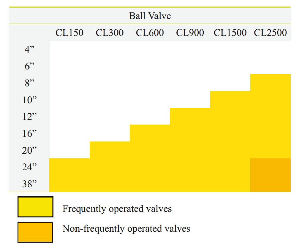 Figure 1 Ball valve actuator requirement for ease of operation
2 Actuator types and hydraulic actuators
Generally, there are three types of actuators in the offshore sector of the oil and gas industry: electrical, pneumatic, and hydraulic (API 2012 & ISO 2011). An electrical actuator is a motor that is installed on the valve for ease of operation. This type of actuator has a fail-as-is (FAI) function, which means that the actuator remains in the last position in case of actuator failure or power loss. An electrical actuator is lighter, more compact, and less costly compared to pneumatic and hydraulic actuators.
However, the speed of operation is slower, and the standard electrical actuator cannot maintain the valve in a fully closed or open position in case of failure. Basically, there are two ways to accomplish a "fail safe" position for an electrical actuator through using a compressed spring inside the actuator or using electro-hydraulic actuators (Emerson, 2019).
The next type of actuator is pneumatic that is working with air in 0.9 MPa have an advantage of environmentally friendly operation. A pneumatic actuator could be a very big and expensive option for a large size and high-pressure class valve such as a 38" ball valve in Class 150 installed on a pipeline with a fail-safe function, so a hydraulic actuator is the best choice for this application. Because the oil pressure is high (such as 20 times the air pressure in a pneumatic actuator) and the fluid is not compressible, a hydraulic actuator can produce a large amount of force. Thus, the advantages of hydraulic actuators over pneumatic are that they are more compact, produce a higher torque, and they are suitable for larger and higher-pressure class applications as well as having higher degree of corrosion protection in the hydraulic fluid compared to air (Flowserve, 2018).
A hydraulic actuator is a cylinder that uses hydraulic power and converts it to mechanical work. Hydraulic actuators can be quarter-turn (Figure 2), which can be used for ball valves, or linear, which are selected for linear valves such as globe valves (Schlumberger, 2018). For example, high oil pressure in 180 barg or 18 MPa average enters the cylinder of the actuator, pushes the spring back, and transfers the linear movement to a quarter-turn (90°) rotary movement through the scotch and yoke. In case of failure in the system or actuator, the spring returns the valve to a fail-safe mode, which is either the open or closed position.
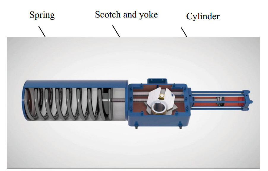 Figure 2 Quarter-turn hydraulic actuator (Sotoodeh, 2019c)
It is possible to have double-acting hydraulic actuators utilizing pressurized oil on both sides for opening and closing a valve (see Figure 2). The side of the actuator with higher oil pressure makes the movement required to actuate the valve (Schlumberger, 2018). There is no spring in double-acting actuators to move the valve to either open or closed positions (Pishock, 2016). A double-acting hydraulic actuator can produce higher torque and it is more compact compared to single-acting actuators. Thus, double-acting actuators are typically selected for the applications where required torque or thrust values are higher than spring return single-acting cylinders (Kevin, 2019) It should be noted that double-acting actuators do not have fail-safe functions, which means that remain in the last position in case of failure in the system, a condition called fail-as-is (FAI).
3 Aim of research, contribution and main research questions
Double-acting hydraulic actuators are selected for valves in the offshore sector of oil and gas projects including subsea. Double-acting actuators have a weak point of not staying in a safe position (closed or open) in case of losing the power source or any other failure. This research was conducted to determine why and in which applications double-acting hydraulic actuators have been selected, and how the double-acting hydraulic actuator dimensions and volumes can be calculated. Lack of literature about the reasons for double-acting hydraulic actuator selection was the main motivation to carry out this research.
A combination of theoretical and experimental approaches was used in this research. When it comes to a practical approach, two case studies about the usage of double-acting hydraulic actuators will be reviewed in this paper related to the offshore sector of the oil and gas industry. The first case addresses the selection of a double-acting hydraulic actuator for a 38" Class 1 500 emergency shut down (ESD) ball valve as well as design changes and modification consequences. The first case is related to a topside offshore project named Johan Sverdrup in the Norwegian continental shelf. The second practical study and review will be done on the valves for a subsea project named Rovuma, located on Mozambique's northern border with Tanzania.
This theoretical review will be conducted using three papers discussing the design and analysis of hydraulic actuators, operating torque for ball valves, as well as optimization of shutdown valve actuator weight. These three papers have been selected in this review to connect the valve required torque with actuator sizing and selection, finding practical ways for actuators' weight optimization, as well as developing a theoretical model to calculate the actuators' thicknesses and dimensions for the 38" CL1500 ball valve in the Johan Sverdrup project.
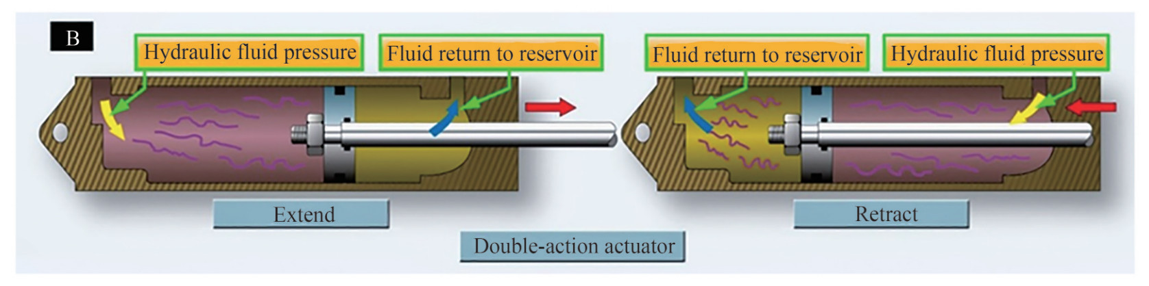 Figure 3 Double-acting linear hydraulic actuator (Sotoodeh, 2019c)
The following are the main contributions of this study:
• Use of double acting actuators in the offshore oil and gas industry in order to save space and weight in comparison to another type of hydraulic actuator. It is important to note that in the offshore oil and gas industry, weight and space savings are always a challenge.
• Possible consequences of using a double-acting actuator, such as using an accumulator and fire protection
• Reduce weight, space, and cost by optimizing the actuator sizing and design.
4 Case study
4.1 Johan Sverdrup project, 38" CL1500 ball valve double-acting actuator
The Johan Sverdrup project is one of the five largest oil fields on the Norwegian continental shelf (Equinor 2019). This project is known as one of the most important industrial projects in Norway for the next 50 years (Equinor 2019).The expected oil produced from the field is estimated at 2.7 billion barrels of oil (Equinor 2019). The project development can generate employment of at least 150 000 man-years in Norway from 2015 to 2025 (Equinor 2019). The field is located 160 kilometres west of Stavanger, a city in the west of Norway (Equinor 2019). The project contains four platforms: riser, drilling, process, and living quarters (see Figure 4).
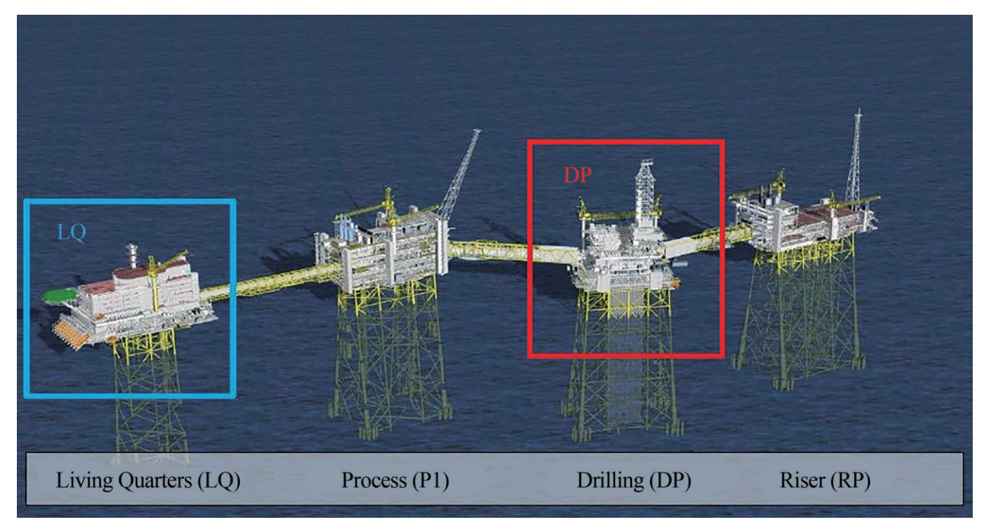 Figure 4 Johan Sverdrup project platforms (Equinur, 2019)
The riser platform contains an oil export pipeline in 38" size and CL1500 to transport the oil from the platform to the shore through the sea. There are three valves located on the oil export line on the platform upstream of the connection between topside and the subsea pipeline (see Figure 5). These valves are normally large size, 38" in this case, in high pressure classes, which makes them critical in terms of engineering design and delivery time(Sotoodeh, 2015; 2018) The last valve on the oil export line, which is connected to the subsea line based on Det Norske Veritas (DNV) code, has an emergency shutdown function. DNV is a company based in Norway setting codes and standards related to offshore oil and gas industry. In fact, the valve should be closed in case of failure in the pipeline to prevent loss of production and maintain Health, Safety and Environment (HSE) issues. The valve is approximately 67 tonnes, so it should be equipped with a hydraulic actuator because it is very large and in a high-pressure class. The initial actuator selection in the project was a spring return hydraulic actuator to achieve a fail-safe closed function. But two problems were reported by the actuator manufacturer regarding the spring return hydraulic actuator selection that changed the actuator selection to double-acting hydraulic type. Figure 6 illustrates the 38" Class 1 500 ESD valve with a double-acting actuator which has been tested and ready to be shipped to the construction yard in Korea. Installation of all facilities, including valves, will take place in South Korea, and the completed module will be shipped to Norway. This is due to the fact that construction jobs in South Korea are significantly less expensive than those in Norway
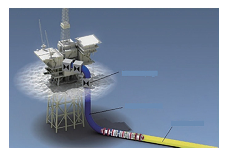 Figure 5 Pipeline including the valves from topside to the shore
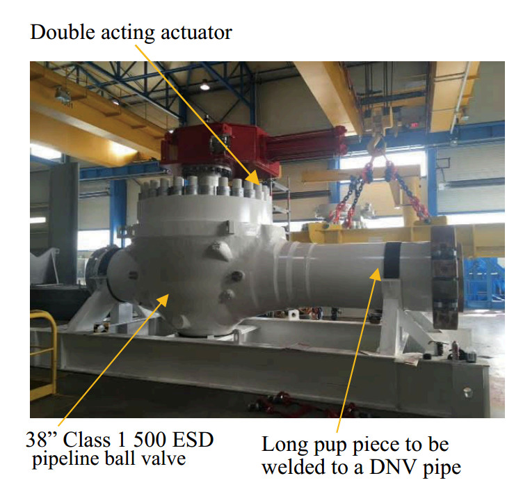 Figure 6 38" Class 1 500 ESD pipeline ball valve with double-acting hydraulic actuator
The first problem was that the spring return actuator for this valve could weigh nearly 15 tonnes. Adding approximately 15 tonnes of weight from the actuator on the top of the huge valve that weighs approximately 82-tonne valve would make the valve difficult to handle and challenging, both in terms of actuator installation on the valve as well as transportation of the valve and actuator assembly. It should be noted that the valve and actuator had to be assembled in the valve manufacturer factory, located in South France, and then shipped to South Korea. In the Norwegian oil industry, it is common to buy valves and actuators from European countries including Italy, Germany, the United Kingdom or France since there are a number of high-class valve manufacturers in these countries. Furthermore, there is no strong valve manufacturing industry in Norway like in the other mentioned countries. For cost-saving reasons, all facilities, pipes, and structures are assembled in South Korea instead of Norway.
The solution was to change the actuator selection from single-acting to double-acting hydraulic type, which resulted in a 10 tonnes actuator weight reduction. The other problem associated with spring return hydraulic actuator selection was not maintaining the actuator sizing safety factors. The requirement from the end user was to apply a safety factor of a minimum of 2 for actuator sizing in both closing and opening actions. A safety factor of a minimum of 2 means that the actuator should produce torque values of at least twice the actual torques required to operate the valve (API 2012; ISO 2011). A very strong and high torque spring should be selected for the actuator to achieve a safety factor of a minimum of 2 on the closing of such a large size and high-pressure class valve. Thus, the actuator manufacturer could not manufacture a single-acting actuator with a safety factor of a minimum of 2 on oil action (opening) during the first part of the valve opening action, called break to open (BTO). The oil force could overcome the large spring force in the actuator and get the valve open with only a safety factor of approximately 1.7–1.8. Selecting a double-acting actuator that could produce higher torque values satisfied the safety factor of 2.
What are the consequences of actuator selection modification for a large size ball valve? The ESD valve with a double-acting actuator is fail-as-is and cannot achieve fail-safe closed (FSC) function. Therefore, an accumulator with oil capsules was selected to stroke the valve to a fully closed position (see Figure 7). The bottles of oils are pressurized by nitrogen to provide the force for three valve strokes. The capsules are kept inside a safety box for safety reasons such as fire protection.
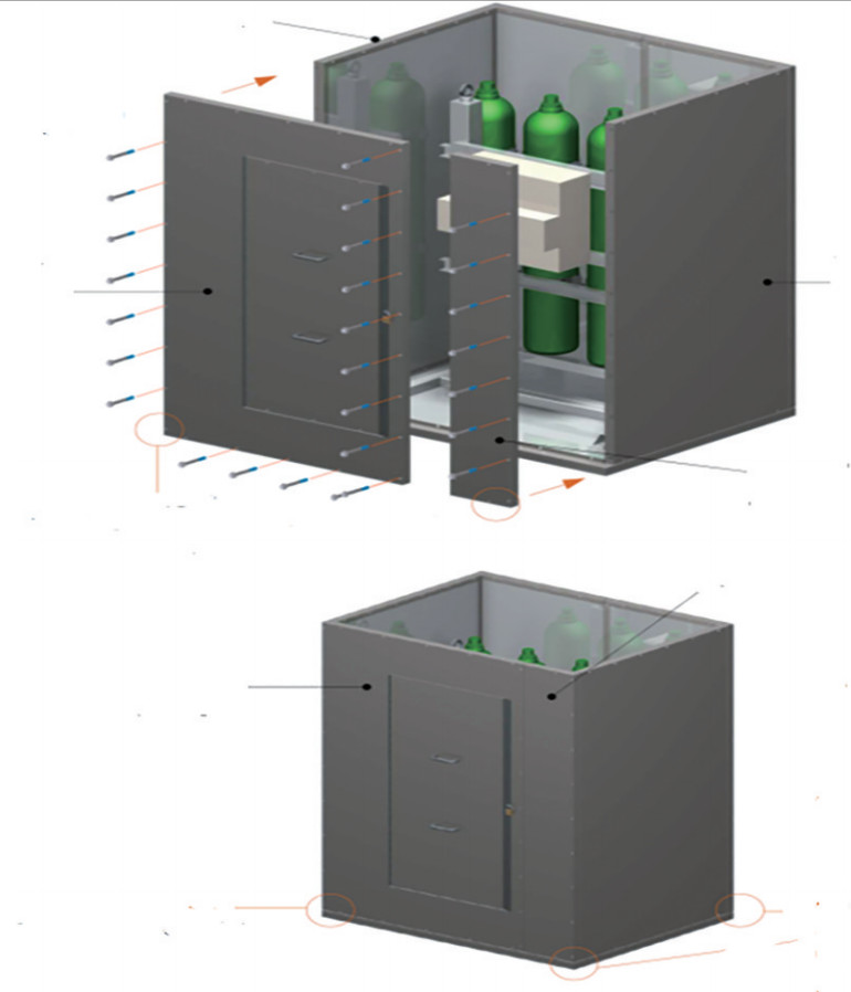 Figure 7 Oil capsules inside the fire box
The fire box or passive fire protection is required to be installed in the construction yard around the double-acting actuator (see Figure 8) (Sotoodeh, 2019a) in addition to oil capsules. The double-acting hydraulic actuator is operated totally with oil in both opening and closing actions, so it must be protected against an oil fire in case of fire occurrence. Using a fire box is not a case for the spring return actuators since they are returned to a safe mode, in either open or closed position, in case of fire. The other important consideration is to evaluate the requirement for adding supports on the coupling between the valve and actuator (see Figure 8) to improve the coupling resistibility against the actuator and fire box weights.
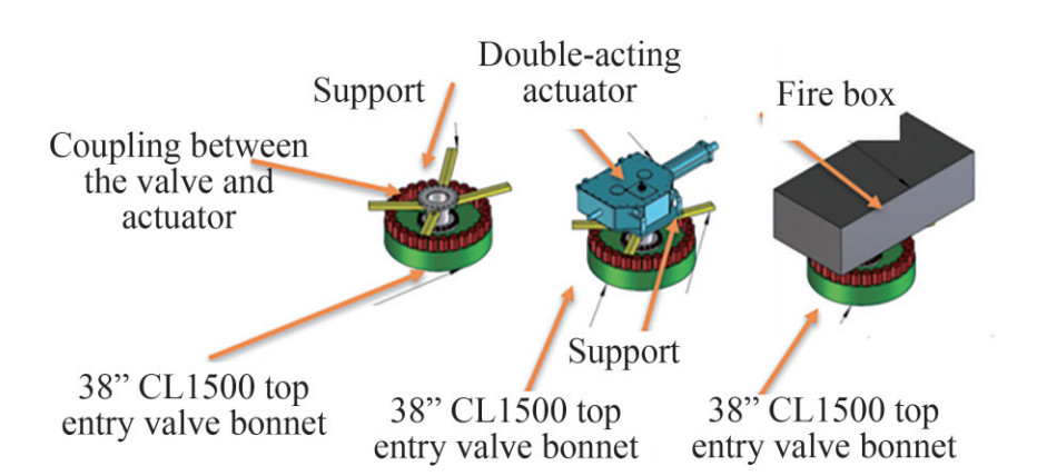 Figure 8 Fire box around the actuator plus supports under the actuator
4.2 A subsea project, 24" and 18" ball valves with double-acting actuator
A subsea LNG project aimed to produce natural gas from subsea gas reservoirs in the deep water, approximately 2 kilometres deep, located in Africa. The project includes tie-back (connection) of 30 offshore wells to the onshore liquefied natural gas (LNG) plant. LNG includes less volatile and more liquefied forms of gas such as propane and butanes. LNGs are more valuable than volatile natural gas, so it is worth it to separate them from natural gas in the form of liquid.
A production system consists of subsea completed well (s), seabed wellhead(s), production tree(s), subsea tie-ins to a flow line system, and subsea equipment and control facilities to operate the well(s) (Sotoodeh, 2019b; Bai, Y. & Bai, Q, 2012). A typical subsea field architecture is illustrated in Figure 9 and includes subsea structures and equipment such as subsea manifolds, pipeline ends and inline structures, jumpers, subsea wellheads, subsea tress, umbilical systems, production risers, and subsea pipelines (Sotoodeh, 2019b; Bai, Y. & Bai, Q, 2012).
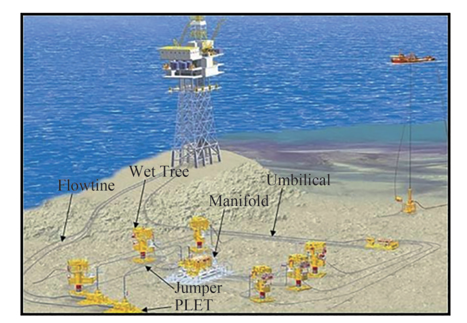 Figure 9 Typical subsea production system (Bai, Y. & Bai, Q., 2012).
The case study of the project in this paper covers actuated valves in the subsea manifolds. Subsea manifolds (see Figure 10) are used to simplify the subsea system, minimizing the usage of a subsea pipeline and risers as well as optimizing the fluid flow(Sotoodeh, 2019b; Bai, Y. & Bai, Q, 2012).
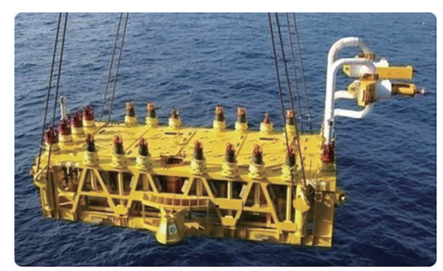 Figure 10 Subsea manifold
Manifolds are installed on the seabed to gather production from different wells or inject water or gas into the wells for advanced oil recovery(Sotoodeh, 2019b; Bai, Y. & Bai, Q, 2012).
The manifold structure is the arrangement of piping and valves designed to integrate, distribute, and control the flow(Sotoodeh, 2019b; Bai, Y. & Bai, Q, 2012).
The project contains between 11 subsea manifolds including more than 182 pieces large size 2" to 24" actuated valves on the manifolds. The numbers of the valves given in this paper are evaluated based on early engineering work in this project. The project contains 3 export manifolds, 4 off 4-slot manifolds, and 2 off 6-slot manifolds. The 4- and 6-slot manifolds are production manifolds connected to 4 and 6 drilled wells respectively (DNV, 2000). Export manifolds are located downstream of production manifolds that receive the produced fluids from the production manifolds and transport them to the facilities in the shore. Figure 11 shows a Process Flow Diagram for a 6-slot production manifold (DNV, 2000). The same flow diagram is expected from a 4-slot manifold except for the numbers of the connected wells, which are 4 offs. It should be noted that export manifolds have similar flow diagrams. Although through conduit gate valves are preferred for sizes 10" and below, and ball valves are preferred for larger sizes, that is not always the case for every project (DNV, 2000 & Bai, Y. & Bai, Q, 2012).
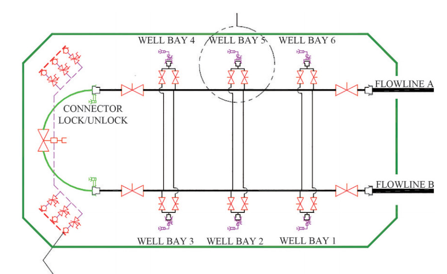 Figure 11 6-slot subsea production manifold process flow diagram
The valves on the branches are normally in gate valves and the larger size valves on the header are ball valves. Actuated gate valves have an FSC function with spring return hydraulic actuators to close the gate valves and disconnect the manifold from the upstream well in case of any operational problem on the well(s).
Table 1 shows the numbers of the large size actuated valves in 2" and above in all manifolds in the project in the early engineering phase. 26-off largest size ball valves which are 24" (6-off) and 18" (20-off) with pressure class of 59 MPa are equipment with double-acting hydraulic actuators. Other 156 valves in size ranges between 2" to 18" are equipped with spring return hydraulic actuators. 24" double-acting actuated ball valves are located on the headers of export manifolds, and 18" double-acting actuated ball valves are located on the headers of production manifolds. There is probably no need to have spring return FS actuators for these valves since branch gate valves with FSC action would isolate the manifolds from the upstream well or module in case of failure. Further research is proposed to investigate why FS action is not expected from those 26 pieces of valves. However, Case Study #2 shows that double-acting hydraulic actuator has been used for the largest size valves in the project, which leads to weight reduction and a more compact design for the valve and actuator assembly. The following sections will review three academic papers related to the topic of this article.
The two case studies provided above demonstrate the application of double-acting hydraulic actuators both in topside and subsea offshore oil and gas projects. However, no details regarding essential design considerations are provided for these actuators, such as their sizing, safety factor, weight optimization, or evaluation of load or stress. As a result, three papers related to the above topics are reviewed in the following part of the manuscript. The primary focus of the first paper is on actuator torque values as well as their relationship to valve torques. As a follow up, the second paper looks at weight optimization through design parameters, such as fluid pressure and safety factor. Finally, the third paper examines the load analysis of actuators.
5 Review of papers
5.1 Operating torque in ball valves
The paper titled, "Operating torque in ball valves–A review" was selected because it defines different torques for operating a ball valve as well as the torque measuring tool (Gokilakrishnan G., et al., 2014). The strength of Paper #1 is that it helps readers understand different operating torques in an important valve, the ball valve. Ball valves are known as the most important, complicated, and expensive valves in the offshore sector of the oil and gas industry. This paper was selected for review because sizing the actuator is done through understanding and having the valve torque values. The valve torques are given by the valve manufacturers as a basis for sizing actuators.
There are six torque values associated with valves, including ball valves (Gokilakrishnan G., et al., 2014):
1. Break to open (BTO): This torque is measured when the valve is closed and the ball opens against just one seat under pressure. This torque, also called breakaway torque, was calculated earlier.
2. Running torque (RT): The torque of the valve when the ball opens at approximately 35° to 45°.
3. End to open (ETO): The torque required to fully open the valve when the ball opens at the 80° closed position.
4. Break to close (BTC): When the valve is in the fully open position, the torque required to break the open position of the valve to close the valve.
5. End to close (ETC): The torque required to fully close the valve when the valve is about to close.
6. BTO with double block: This torque is measured when the valve is closed and the ball opens against both seats under pressure.
Figure 12 shows the position of the ball in different torque conditions.
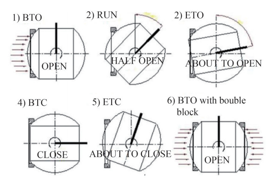 Figure 12 Position of the ball in different torque conditions
Paper #1 emphasized enough safety margins to size the actuators. However, the research does not give any model or formula to connect and correlate the torque values in a valve and the related actuator. A safety factor or margin of a minimum of 2 based on the end user requirement should be considered for the 38" CL1500 ESD valve discussed in section 4 of this paper. Equation 1 defines the relationship between the valve and actuator torque considering the safety factor.
$$ \text { Safety factor }=\frac{\text { Actuator torque }}{\text { Valve torque }} $$ (1) It should be noted that each valve torque condition (i.e., BTO) should be compared with the relevant actuator torque value (BTO). Thus, the safety factor for actuator sizing is created in five or six different positions as mentioned earlier. Table 2 contains torque values given by a valve manufacturer for a 38" CL1500 ball valve, reviewed in Case Study #1, as well actuator torque values considering a safety factor of 2.
Table 2 38" Cl1500 ESD valve and actuator operating torque valuesValve torque values (N·m) BTO RUN ETO BTC ETC 348939 61510 139794 348939 139794 Actuator torque values (N·m) (Safety factor of 2) BTO RUN ETO BTC ETC 697878 123020 279588 697878 279588 In practise, the actuator torque is not exactly double the valve torque when a minimum safety factor of 2 has been specified. Practically speaking, an actuator is selected by an actuator supplier that can satisfy a minimum safety factor of 2.
5.2 Optimization of ESD valve size and weight
The paper titled "Optimization of Shut Down Valve Weight and Size" is reviewed in this paper (NAIR, 2016). because it provides optimization techniques for actuators' weight and size reduction for ESD ball valves in the offshore industry. The techniques discussed in Paper #2 can be evaluated to see whether or not they are applicable for the 38" CL1500 ball valve discussed in section 4 of this paper. Paper #2 has a review of different torque types as discussed in Paper #1 (Gokilakrishnan G., et al., 2014; NAIR, 2016)
The strength point of the paper is that weight analysis has been done for scotch and yoke actuators installed on ESD ball valves, which is the same as the valve discussed in Case Study #1(NAIR, 2016). The weak point of the paper is that the weight analysis has been done for single-acting pneumatic actuators and not hydraulic types (NAIR, 2016). However, the results provided for pneumatic actuators can be extended to hydraulic types. The paper compares the actuators' weight values for 167 pieces of the valves in size ranges from 2" to 18" in ASME pressure classes of 150, 300, 600, 900 and 1 500 (NAIR, 2016). The pressure classes of 150, 300, 600, 900, and 1 500 are equal to pressure nominal values of 2, 5, 10, 15, and 25 MPa, respectively (ASME 2004; 2017, Nesbitt, 2007; API 2014). The actuator weights for ESD ball valves in the previously mentioned sizes and pressure classes have been given and compared for three different case scenarios:
1. Actuator weight evaluation based on a safety factor of 2.
2. Actuator weights based on supplier selection charts
3. Actuator weights based on an air pressure of 0.65 MPa which is the average air supply pressure
The total weight of actuators for all three cases have been given 39, 28.3, and 31.3 tonnes, as illustrated in Figure 13(NAIR, 2016).
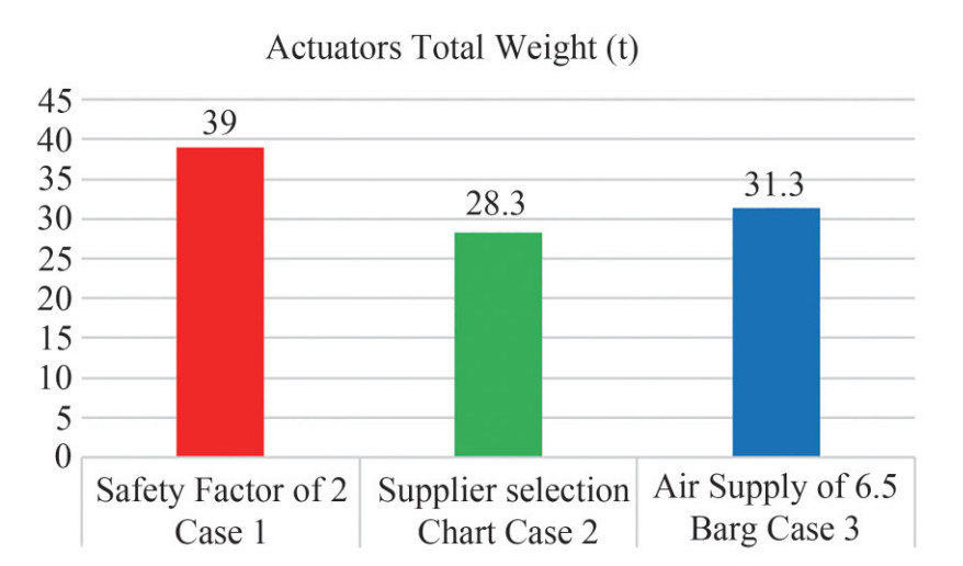 Figure 13 Actuators weight comparison for 167 pieces of ball valves (NAIR, 2016)
The paper provides values of the overall size and space taken by the actuators in each case in cubic meters (see Figure 14) (NAIR, 2016).
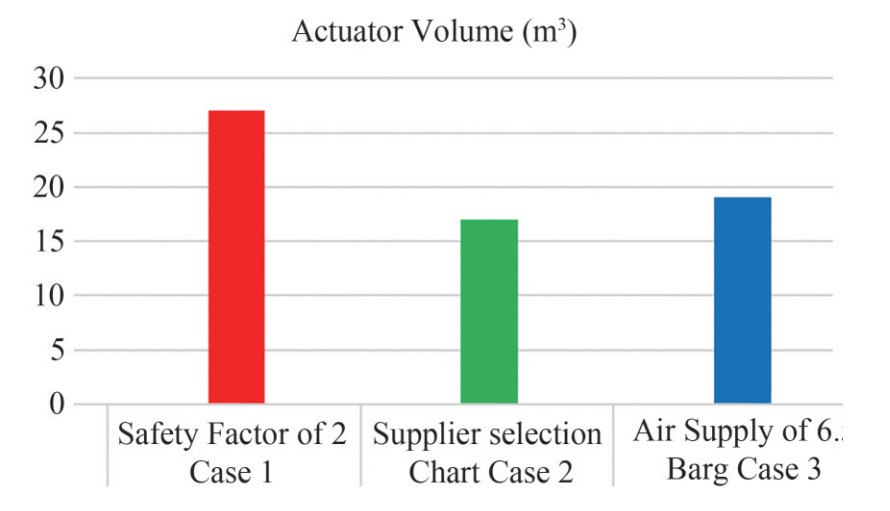 Figure 14 Actuators volume comparison in cubic meter for 167 pieces of ball valves (NAIR, 2016)
The research gap in Paper #2 is how to develop a model based on formulas to evaluate and calculate the actuators volume and weight. Thus, sections 9 and 10 of this paper propose a quantitative methodology based on formulas and calculations for estimating both spring return and double-acting actuators.
The optimized proposed method for actuator sizing and weight reduction in Paper #2 is to ask the actuator supplier for the safety factor, referring to case #2 in chart #1 and 2. (NAIR, 2016). The risk of this approach is under sizing the actuator in a way that the actuator could not open or close the valve properly. In addition, the supplier criteria (approach) used to select the optimum actuator is not clear in the paper. Looking at a 38" ball valve CL1500 in the Johan Sverdrup project, Case Study #1, the safety factor of 2 is always required for the whole required torques for opening and closing the valve based on end user requirements. Thus, a proposed safety factor of less than 2 in this case cannot be approved by the end user and the provided solution in Paper #2 does not work for the valve in Case Study #1. The second proposal in the paper to reduce the actuator weight is to avoid keeping the safety factor constant in all the operating torques. The second proposal is not helpful to reduce the actuator weight for a 38" CL1500 ball valve, since the safety factor of 2 is required for the valve during the whole travel distance of the ball.
The weak point of Paper #2 is that the weight analysis has been done for single-acting pneumatic actuators and not hydraulic types. The maximum, minimum, and average air supply pressure is 0.75, 0.55 and 0.65 MPa, respectively. (NAIR, 2016). Thus, the average air pressure equal to 0.65 MPa should be converted to average hydraulic pressure in the Johan Sverdrup project, which is 18 MPa. Changing the pneumatic pressure to hydraulic will make the actuators more compact and lighter compared to the values provide in Figure 11 and Figure 12. The other weak point of Paper #2 is that the air pressure in Case Study #1 and the safety factor in Case Study #3 have not been specified clearly. In conclusions, the proposals in Paper #2 are not helpful to reduce the size and weight of the actuator in Case Study #1.
5.3 Design and analysis of a double-acting hydraulic actuator
This paper titled, "Design and Analysis of a Double-Acting Hydraulic Actuator" was selected for review because it provides formulas and calculations for pressure containing of a double-acting actuator such as a piston rod, a piston, and a cylinder based on input values such as hydraulic pressure, available material for actuator parts, stroke length, etc. (API 2014). The strength of Paper #3 is providing equations for sizing the actuator parts (see Figure 15) such as the piston rod diameter, piston diameter, and cylinder diameter. (API 2014). It should be noted that for a double-acting actuator, the diameter of piston and cylinder are equal, so there is no need to use the cylinder diameter formula given in Paper #3. However, the cylinder diameter calculation formula given in Paper #3 is recommended for calculation of the spring house (cylinder) in a single-acting actuator.
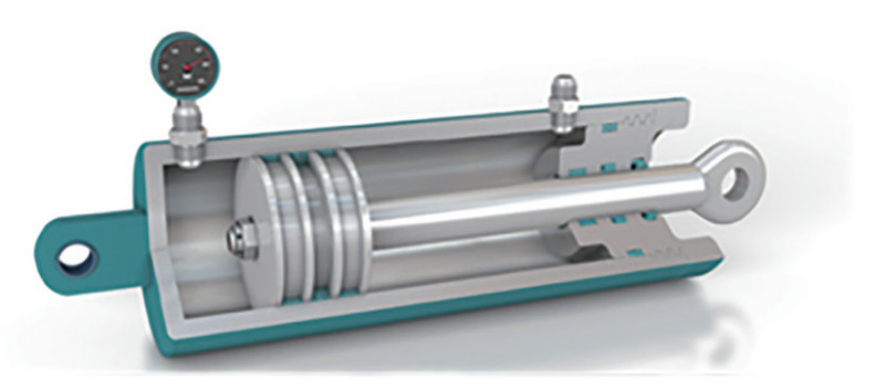 Figure 15 Double acting hydraulic cylinder
The following input data are assumed to be known in actuator design calculation (Boye E., et al., 2017)
Poil = The hydraulic pressure (Pa);
Patm = Atmospheric pressure (Pa);
L= Stroke length (m);
F= Output force of actuator considering safety factor (N);
K= End fixing factor = 0.7;
σt = Tensile stress of actuator material (Pa);
Yt = Yield stress of actuator material (Pa);
E = Young modulus of the actuator material (Pa);
τ = Actuator torque (N·m);
Equations #2 and #3 are used for design of the piston rod and calculating parameter (d) which is the piston rod diameter in meters.
$$F = \frac{{{{\rm{ \mathsf{ π} }}^2}EI}}{{{L^2}{K^2}}} $$ (2) $$ I = \frac{{{\rm{ \mathsf{ π} }}{d^4}}}{{64}} $$ (3) "I" is the moment of inertia (m4), which is calculated using Equation #2. The design of the piston is done by calculating the piston diameter (D) in meters as shown in Equation # 4.
$$ F = {P_{{\rm{Oil }}}} \times \frac{{{\rm{ \mathsf{ π} }}\left({{D^2} - {d^2}} \right)}}{4} $$ (4) Two more dimensions of cylinder, outside diameter (OD) and thickness (t), should be calculated using Equations # 6 and 7.
σm = Maximum working stress (Pa)
SF = Safety factor
$$ {\sigma _m} = \frac{{{\sigma _t}}}{{{\rm{SF}}}} $$ (5) $${\rm{O}}{{\rm{D}}^2} = \frac{{{D^2}\left({{\sigma _m} + {P_{{\rm{Oil }}}}} \right)}}{{\left({{\sigma _m} - {P_{{\rm{Oil }}}}} \right)}} $$ (6) $$ t = \frac{{{\rm{OD}} - d}}{2} $$ (7) An oil double-acting actuator with a hydraulic pressure of 20 MPa and output force of 11kN was selected in Paper #3 for design and analysis (Boye E. et al., 2017). The stroke length of 140mm and safety factor of 3 were considered in this case. The material of the actuator is low carbon steel grade BS970 070M20. The following calculations have been done for designing different parts of the actuators:
- Design of piston rod (diameter calculation)
- Design of the piston (diameter calculation)
- Design of the cylinder (outside diameter and thickness calculation)
- Bursting stress calculations
Finite element analysis (FEA) in Solidworks has been done to validate the double-acting hydraulic design and calculations mentioned earlier. Figures 16 and 17 illustrate the stress intensity on the piston and piston rod as well as cylinder under the oil pressure of 20 MPa and output force of 11 kN. The result of FEA shows that the stress values on the actuator components are below the material yield strength, so using the formulas and calculations have been validated through FEA. The calculations and methodology in this section will be used in the next part of the paper to design the double-acting actuator for the 38" CL1500 ball valve in the Johan Sverdrup project.
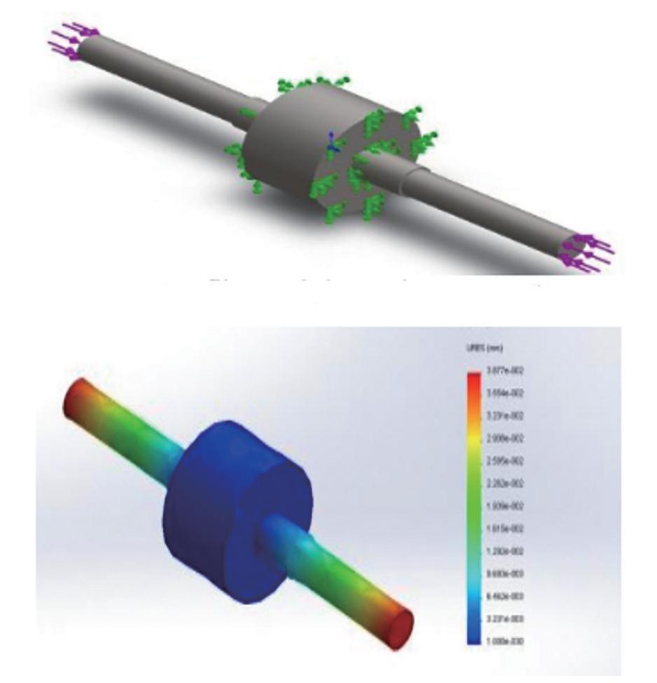 Figure 16 Piston and piston rod stress analysis under load of 11kN
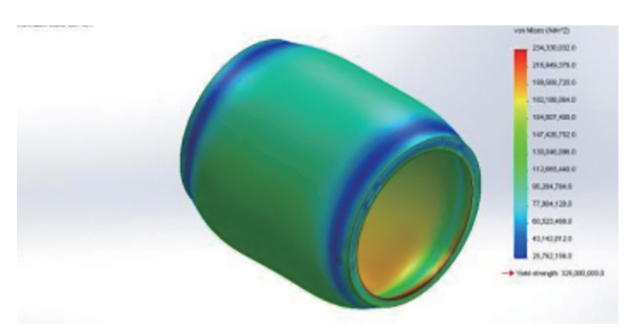 Figure 17 Cylinder stress analysis under 200 barg hydraulic oil pressure
6 Double-acting actuator design and calculations for 38" CL1500 ball valve in Johan Sverdrup project
The methodology shown in Paper #3 for actuator design and analysis is used for the design and calculations of 38" CL1500 ball valve double-acting hydraulic actuator. As shown in Table 3, the maximum torque for a 38" CL1500 ball valve is 348939 N·m. The actuator-produced torque should be double the valve torque equal to 697 878 N·m regarding a safety factor of 2. It is assumed that low carbon steel grade BS970 070M20 material has been used for the actuator and the stroke length (L) of the actuator is 2m. The hydraulic oil pressure is 18 MPa. Using Equation #2:
$ F = \frac{{{{\rm{ \mathsf{ π}}} ^2}EI}}{{{L^2}{K^2}}} \to $ Both F and I are unknown, so parameter "F" should be calculated first using Equation (8):
$$ \tau = F \times L $$ (8) → 697 878 = F × 2 → F = 348 939 N
Placing F in Equation #2 → 348939 = $ \frac{{{{\rm{ \mathsf{ π} }}^2} \times 210 \times {{10}^9} \times I}}{{4x0.7x0.7}} \to I = 3.30 \times {10^{ - 7}}\;{m^4}$
Equation #3: $ I = \frac{{{\rm{ \mathsf{ π} }} {d^4}}}{{64}} \to 3.30 \times {10^{ - 7}} = \frac{{{\rm{ \mathsf{ π} }} {d^4}}}{{64}} \to {d^4} = 6.72 \times {10^{ - 6}}\to$
Rod diameter: d = 0.05 m = 50 mm
Formula 4: $ F = {P_{{\rm{Oil }}}} \times \frac{{{\rm{ \mathsf{ π} }}\left({{D^2} - {d^2}} \right)}}{4} \to 348\;939 = 180 \times {10^5} \times \frac{{3.14\left({{D^2} - 0.002\;5} \right)}}{4} \to $
D2 = 0.027 2 m → D = 0.165 m = 165 mm (piston diameter)
Assuming that the cylinder and piston diameter are equal for a double-acting actuator as shown in Figure 13, it is possible to calculate the thickness of actuator using Equation #7.
$$ t = \frac{{{\rm{OD}} - d}}{2} = \frac{{D - d}}{2} = \frac{{D - d}}{2} = \frac{{165 - 50}}{2} = 57.5\;{\rm{mm}} $$ Using TRELLEBORG hydraulic calculation software (Figure 18) provides volume and areas on the piston side and the rod side of the actuator, providing the input data of bore diameter, rod diameter, stroke, and oil pressure.
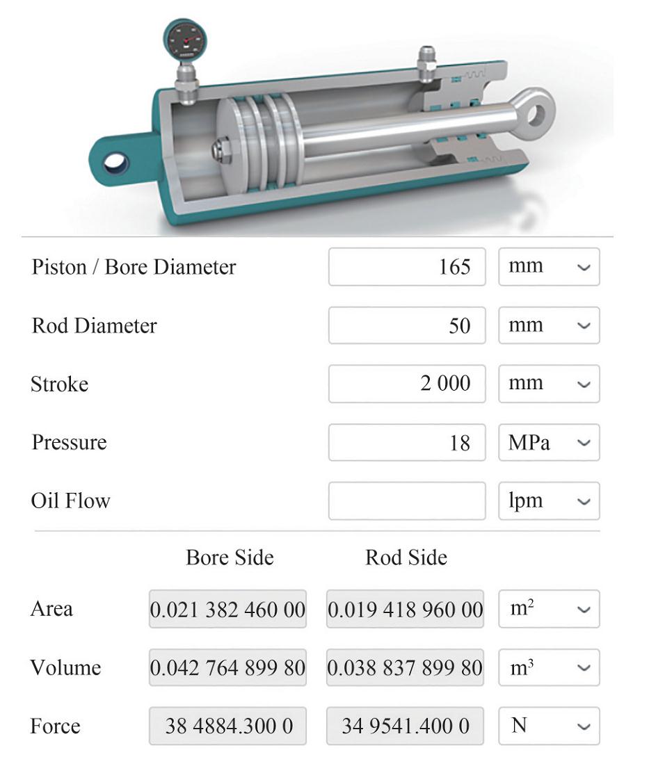 Figure 18 38" Cl1500 ball valve double acting actuator
7 Conclusion
This article reviewed two case studies in the offshore oil and gas industry in which a double-acting hydraulic actuator was selected instead of a single-acting hydraulic actuator for weight reduction for relatively large-sized ball valves. A future study has been proposed for using double-acting hydraulic actuator selection for using in non-fail-safe function applications. In two offshore projects—Johan Sverdrup in Norway and Rovuma on the border between Mozambique and Tanzania—double-acting hydraulic actuators have been selected for ball valves in sizes 16", 22", and 38". Three papers were reviewed and evaluated in this article. The first paper discusses operational torques in the ball valves. Six different torques used for sizing and designing the actuators were reviewed in this paper. The second paper discusses implementation of approaches in order to optimize the size and weight for actuators used for emergency shutdown valves. The third paper provides calculations and formulas for design and analysis of double-acting actuators. Finally, the methodology and calculation methods provided in Paper #3 have been used for designing and sizing the double-acting actuator used for the 38" ball valve CL1500 in the Johan Sverdrup project. Future research is proposed to compare the weight of double-acting and single-acting hydraulic actuators as well as developing a method for weight calculations of single-acting hydraulic actuators.
-
Figure 1 Ball valve actuator requirement for ease of operation
Figure 2 Quarter-turn hydraulic actuator (Sotoodeh, 2019c)
Figure 3 Double-acting linear hydraulic actuator (Sotoodeh, 2019c)
Figure 4 Johan Sverdrup project platforms (Equinur, 2019)
Figure 5 Pipeline including the valves from topside to the shore
Figure 6 38" Class 1 500 ESD pipeline ball valve with double-acting hydraulic actuator
Figure 7 Oil capsules inside the fire box
Figure 8 Fire box around the actuator plus supports under the actuator
Figure 9 Typical subsea production system (Bai, Y. & Bai, Q., 2012).
Figure 10 Subsea manifold
Figure 11 6-slot subsea production manifold process flow diagram
Figure 12 Position of the ball in different torque conditions
Figure 13 Actuators weight comparison for 167 pieces of ball valves (NAIR, 2016)
Figure 14 Actuators volume comparison in cubic meter for 167 pieces of ball valves (NAIR, 2016)
Figure 15 Double acting hydraulic cylinder
Figure 16 Piston and piston rod stress analysis under load of 11kN
Figure 17 Cylinder stress analysis under 200 barg hydraulic oil pressure
Figure 18 38" Cl1500 ball valve double acting actuator
Table 1 List of large-size actuated valves
Valve type NPS(") Operator Fail mode Pressure rating (MPa) Total Ball valve 24 Hydraulic double-acting FAI 59 6 Ball valve 18 Hydraulic double-acting FAI 59 20 Ball valve 18 Hydraulic spring return FSC 59 10 Ball valve 10 Hydraulic spring return FSC 59 22 Gate valve 8 Hydraulic spring return FSC 59 80 Gate valve 2 Hydraulic spring return FSC 59 14 Gate valve 2 Hydraulic spring return FSC 59 30 Table 2 38" Cl1500 ESD valve and actuator operating torque values
Valve torque values (N·m) BTO RUN ETO BTC ETC 348939 61510 139794 348939 139794 Actuator torque values (N·m) (Safety factor of 2) BTO RUN ETO BTC ETC 697878 123020 279588 697878 279588 -
American Petroleum Institute (API) (2012) Standard for actuator sizing and mounting kits for pipeline valves. API 6DX, 1st edition. Washington, DC: API American Petroleum Institute (API) (2014) Specification for pipeline and piping valves. API 6D. 24th edition. Washington, DC: API American Society of Mechanical Engineers (ASME) (2004) Valves—Flanged, threaded, and welding end. ASME B16.34. New York, NY: ASME American Society of Mechanical Engineers (ASME) (2017) Pipe flanges and flanged fittings. ASME B16.5. New York, NY: ASME Bai Y, Bai Q (2012) Subsea Engineering Handbook. 1st ed. Elsevier, USA Boye E, Olabisi I, Emagbetere E (2017) Design and finite element analysis of double-acting, double ends hydraulic cylinder for industrial automation application. American Journal of Engineering Research 6 (3): 131-138 Det Norske Veritas (DNV) (2000) Subsea joint industry project (JIP). Norway, Hovik Emerson (2019). Electrical actuators fail to safe position. [Online]. Available from: https://www.spartancontrols.com/applied-technology/valves/isolate/actuation/electric-actuators/fail-to-safe-position/ [access date: 3th of March 2020] Equinor (2019) Johan Sverdrup. [Online]. Available from: https://www.equinor.com/en/what-we-do/johan-sverdrup.html [access date: 3th of March 2020] Flowserve 2018) Valve actuation: The when, how, and why of actuator selection. [Online]. Available from: https://www.flowserve.com/sites/default/files/2018-05/(FLS-VA-EWP-00005-EN-EX-US-0518-Actuation_Type_Advantages_LR1.pdf. [access date: 3th of March 2020] Gokilakrishnan G, Divya S, Rajesh R, Selvakumar V (2014) Operating Torque in ball valves – A review. International Journal for Technological Research in Engineering, 2(4): 2347-4718 Indelac Controls, Inc. (2014) How to select an actuator. Comprehensive Guide. [Online]. Available from: http://www.indelac.com/pdfs/How-to-Select-an-Actuator-Comprehensive-Guide.pdf [access date: 6th of March 2020] International Organization of Standards (ISO) (2011) Petroleum and natural gas industries—Mechanical integrity and sizing of actuators and mounting kits for pipeline valves. ISO 12490. 1st edition. Geneva, Switzerland: ISO Kevin H (2019) Know your Pneumatics: single or double-acting? Choosing the right cylinder. [Online]. Available from: http://blog.parker.com/know-your-pneumatics-single-or-double-acting-choosing-the-right-cylinder [access date: 10th of March 2020] Metalphote of Cincinnati (2018) How to select a valve actuator: Types of valve actuators, appropriate sizing, safety criteria, and more. [Online]. Available from: https://www.mpofcinci.com/blog/how-to-select-a-valve-actuator/#Function [access date: 13th of March 2020] Nair S (2016) Optimization of Shutdown Valve Weight and Size. Offshore Technology Conference. Paper Number OTC-26499-MS Nesbitt B (2007) Handbook of Valves and Actuators: Valves Manual International. Oxford, UK: Elsevier Pishock D (2016) Choosing between a double-acting and spring return actuator. [Online]. Available from: https://valveman.com/blog/double-acting-vs-spring-return-actuators/ [access date: 15th of March 2020] Schlumberger (2018) LEDEEN hydraulic actuators and controls. [Online]. Available from: https://www.products.slb.com/valves/brands/ledeen/ledeen-hydraulic-actuators [access date: 15th of March 2020] Sotoodeh K (2015) Top entry export line valve design considerations. Valve World Magazine. 20(5): 55-61 Sotoodeh K (2018) Pipeline valves technology, material selection, welding, and stress analysis (a case study of a 30-inch class 1 500 pipeline ball valve). ASME, Journal of Pressure Vessel Technology 140(4), 044001, Paper Number PVT-18-1043. https://doi.org/10.1115/1.4040139 Sotoodeh K (2019a) Valve operability during a fire. ASME, Journal of Offshore Mechanics and Arctic Engineering 141(4), 044001, Paper Number OMAE-18-1093, https://doi.org/10.1115/1.4042073 Sotoodeh K (2019b) Subsea and topside offshore valves: a comparison-Part 1. Valve World Magazine. 24(6): 25-27 Sotoodeh K (2019c) Actuator sizing and selection. Springer Nature Applied Science, Springer Switzerland, 1, 1207. https://doi.org/10.1007/s42452-019-1248-z