Propeller Design for an Autonomous Underwater Vehicle by the Lifting-line Method based on OpenProp and CFD
https://doi.org/10.1007/s11804-022-00275-w
-
Abstract
A high-efficiency propeller can enable a long mission duration for autonomous underwater vehicles (AUVs). In this study, a new method with OpenProp coupled with computational fluid dynamics was developed to design a propeller for an Explorer100 AUV. The towed system simulation of the AUV was used to measure the nominal wake, and a self-propulsion simulation was used to measure the effective wake at the disc plane just in front of a propeller. Two propellers referring to the nominal wake (propeller 1) and effective wake (propeller 2) were designed with OpenProp and appended with the AUV for self-propulsion simulations, respectively. Through the numerical simulation of the AUV self-propulsion tests, the cruising velocity of AUV was obtained. The flow characteristics of the self-propulsion in pressure and velocity contours were also analyzed. The propeller designed with an effective wake improved the thrust, velocity, and efficiency by approximately 11.3%, 6.7%, and 2.5%, respectively, as compared with those with a nominal wake. The cruising velocity of the final designed propeller for the Explorer100 AUV improved by 21.8%, as compared to that of the original propeller from the AUV free-running tests.-
Keywords:
- Autonomous underwater vehicle ·
- High efficiency ·
- Propeller ·
- Wake ·
- Lifting line ·
- OpenProp
Article Highlights• Two propellers are designed with OpenProp based on nominal wake and effective wake respectively;• The propeller designed with effective wake improves thrust, velocity and efficiency about 11.3%, 6.7% and 2.5% respectively, comparing with that based on nominal wake;• The cruising velocity of the final designed propeller for the Explorer 100 AUV has improved by 21.8%, compared to that of the original propeller. -
1 Introduction
Autonomous underwater vehicles (AUVs) are untethered vehicles and have been used by military, commercial, and academic operators in different mission scenarios. One of the goals of AUV design is to reduce the power requirement and extend its mission duration with contained limited power. Although the AUV line is optimized to reduce its resistance, designing a propeller with high efficiency is critical for AUVs. Traditionally, an AUV would choose an available commercial propeller due to the costly, difficult, and time-consuming design and fabrication. However, the propeller is not optimized for the capabilities of a specific vehicle. Therefore, it is necessary to design an efficient propeller required for unique vehicle characteristics.
Various design methods for ship propellers are the chartsbased method (Wu et al., 2011; Sheng and Liu, 2013), lifting-line approach, and surface panel method (Epagnier et al., 2007; Su and Huang, 2013; Sun and Huang, 2019). Charts based on the results of standard series tests provide methods that enable standard screws to be designed with minimum computation effort. Although a chart-based method is a fast and reliable method, a lower efficiency is observed as compared with the latter two methods. The surface panel method and lifting-line method require a solution to the radial load distribution of the propeller and are relatively complex.
In recent years, owing to its high efficiency, the liftingline method for propeller design has become increasingly popular in marine applications as an alternative to the traditional chart-based method. Zhang et al. (2019) designed a two-blade propeller for a long-range AUV based on the lifting-line theory. Epagnier et al. (2007) optimized an AUV propeller with a given desiring speed by varying the blade number, propeller diameter, hub position, and chord length distribution. Bellingham et al. (2010) and Li et al. (2017) designed an AUV propeller using OpenProp based on the lifting-line theory. Wang et al. (2019) designed a highly skewed propeller based on the lifting-line theory by considering the harmonic analysis, propeller side slope, and longitudinal inclination. Rao (2017) conducted a hydrodynamic optimization for submarine propulsors based on the panel method and optimization algorithms, including the design of two-dimensional (2D) blade sections, numerical prediction of the effective wake field and tonal noise of propellers, optimization of seven-bladed propellers, and the rotor of a pump-jet propulsor in effective wake fields. Sahili and Zaida (2018) designed a propeller for a remotely operated vehicle (ROV) activated by thrusters, and two propellers with a special blade design were analyzed.
In addition to the conventional propeller design method, an optimization method combined with the conventional propeller design method was recently studied. Kyung et al. (2014) used a lifting surface optimization method coupled with a blade alignment procedure to characterize a vortex lattice discretization of the true blade mean camber surface for the determination of the optimum circulation distribution. Wu et al. (2014) presented the marine propeller design optimization with a genetic algorithm by finding the highest efficiency from chart data. Stefano et al. (2016) devised a new tip-loaded propeller geometry to mitigate some of the downsides of the contracted and loaded tip geometries increasingly adopted to improve the full-scale propeller efficiency. It was designed via an optimization strategy using a boundary element method, a custom parametric description of the unconventional blade geometry, and the genetic algorithm. Wang et al. (2019) presented a wake-adapted theory design and parameter optimization design of propellers to reasonably design a propeller suitable for operation under an accompanying flow field. It was established by combing the harmonic analysis method, propeller side slope, longitudinal inclination selection principle, lift-line program, lift-surface program, unsteady surface element program, and propeller parameter optimization design program. Wang et al. (2020) proposed a propeller optimization method by combing the experimental design method, elliptical basis function neural network approximation model, and genetic algorithm, which can improve the propeller efficiency and reduce the time cost in the optimization process.
This study presents a propeller design for an Explorer 100 AUV to improve its cruising velocity as it cannot reach its cruising velocity appended with its original propeller. The propeller design is based on the lifting-line code of OpenProp and computational fluid dynamics (CFD). The numerical method was demonstrated through open-water tests and self-propulsion tests (Wu et al., 2019; Wu et al., 2020).
2 Methodology
2.1 OpenProp based on a lifting-line theory
OpenProp (Kimball et al., 2008) is a suite of open-source propeller design codes developed by MIT based on the moderately loaded lifting-line theory. The propeller blade is modeled as discrete sections, having velocities and forces on a 2D blade section in the ea axial and et tangential directions, as shown in Figure 1. Va and Vt are the axial and tangential velocities, ua* and ut* are the induced axial and tangential velocities, and ωris the apparent tangential inflow at radius r, respectively. The total resultant inflow velocity, V*, has the following magnitude:
$$ V^{*}=\sqrt{\left(V_{a}+u_{a}^{*}\right)^{2}+\left(\omega r+V_{t}+u_{t}^{*}\right)^{2}} $$ (1) 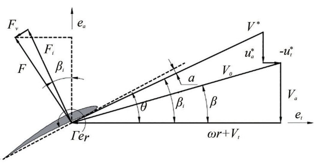 Figure 1 Velocity and force distribution on a 2D blade section
The hydrodynamic pitch angle is βi. α is the angle of attack, θ is the blade pitch angle, Γ is the circulation, Fi is the lift force, and Fv is the viscous drag force.
$$ \beta_{i}=\arctan \left(\frac{V_{a}+u_{a}^{*}}{\omega r+V_{t}+u_{t}^{*}}\right) $$ (2) The efficiency of a single section at radius r is
$$ \eta_{0 r}=\frac{V_{a} \cos \beta_{i}\left(1-\varepsilon \tan \beta_{i}\right)}{\omega r \sin \beta_{i}\left(1+\varepsilon \cot \beta_{i}\right)}, $$ (3) where ε is the lift-to-drag ratio.
The axial and tangential induced velocities are discretized at control points on the lifting line at radial locations rc (m), m=1…M by summing the velocity induced by each horseshoe vortex:
$$ u_a^*\left({{r_c}(m)} \right) = \sum\nolimits_{i = 1}^M \Gamma (i)\bar u_a^*(m, i), $$ (4) $$ u_t^*\left({{r_c}(m)} \right) = \sum\nolimits_{i = 1}^M \Gamma (i)\bar u_t^*(m, i), $$ (5) where ua* (m, i) and ut* (m, i) are the axial and tangential velocities induced at rc (m) by a unit-strength horseshoe vortex surrounding panel i.
The propeller optimization aims to find the set of M circulations of the vortex lattice panels that produce the least torque:
$$ Q = \rho Z\sum\nolimits_{m = 1}^M {\left\{ {\left[ {{V_a} + u_a^*} \right]\mathit{\Gamma } + \frac{1}{2}{V^*}{C_D}c\left[ {\omega {r_c} + {V_t} + u_t^*} \right]} \right\}} {r_c}\Delta {r_v} $$ (6) For a specified thrust,
$$ \begin{array}{l} {T_s} = \rho Z\sum\nolimits_{m = 1}^M {\left\{ {\left[ {\omega {r_c} + u_t^*} \right]\mathit{\Gamma } - \frac{1}{2}{V^*}{C_D}c\left[ {{V_a} + u_a^*} \right]} \right\}} \Delta {r_v}\\ - {H_{{\rm{flag }}}} \cdot \frac{{\rho {Z^2}}}{{16\pi }}\left[ {\ln \left({\frac{{{r_h}}}{{{r_0}}}} \right) + 3} \right]\mathit{\Gamma }{(1)^2} \end{array} $$ (7) where Hflag is set to 1 to model a hub or 0 for no hub. {ρ, Z, ω} are constant and{Γ, ua*, ut*, V*, c, Va, CD, rc, Δrv} are evaluated at each control point radius.
2.2 AUV model
The Explorer100 AUV is a low-cost, man-portable AUV developed at Shenyang Institute of Automation (Chinese Academy of Sciences) for a long-range oceanic survey at an operating speed of 3 kn, with a non-inertial blade fixed coordinate oxyz and inertial coordinate Eξηζ (Figure 2). The origin of oxyz is located at the center of the propeller, and its x-axis coincides with the propeller shaft. The original propeller for the Explorer100 AUV works with a low efficiency, which cannot provide a thrust enough to propel the AUV at an operating velocity of 3 kn at a given power. Therefore, the current effort focuses on designing a new propeller to improve efficiency and provide a large thrust to reach the required operating velocity.
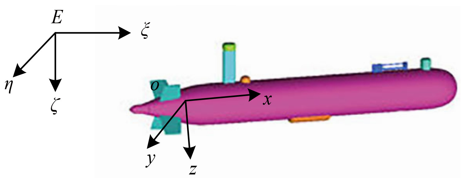 Figure 2 Model of the Explorer100 AUV without a propeller
2.3 Propeller design flow chart
The propeller was designed based on OpenProp codes. At the beginning of the design, the radially varying circumferential inflow is required to be inputted in the graphical user interface. There are two inflows at the disk (Allston et al., 2014; Regener et al., 2018): a nominal wake and an effective wake. The nominal wake is the wake of the AUV in the absence of a propeller, whereas the effective wake is that with the presence of a propeller. The effective wake was contracted and accelerated by a rotating propeller, which modified the wake profile. Therefore, it is important to obtain the wake profile upstream of the propeller to optimize the propeller design. The whole flow chart of the propeller design is shown in Figure 3, which includes three steps: 1) simulate the towed AUV to measure the nominal wake and design an initial propeller (named propeller 1); 2) conduct a self-propulsion test to measure the effective wake to design a final propeller (named propeller 2); and 3) conduct a self-propulsion test to validate the interaction of the AUV and propeller 2 and then compare the performance of the designed propeller with that of the original propeller.
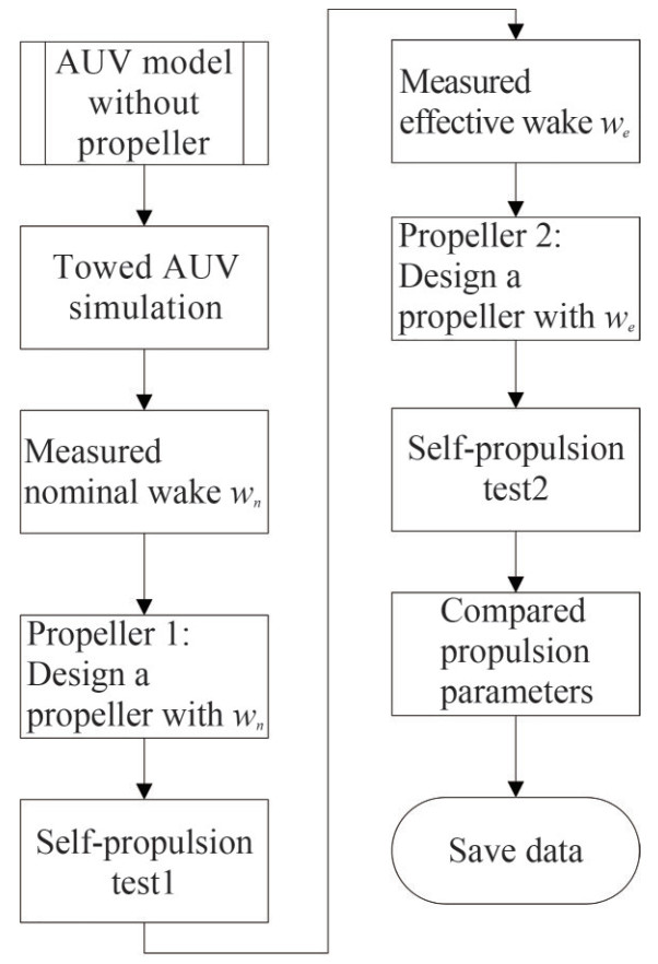 Figure 3 Propeller design flow chart
2.4 Towed AUV simulation
To obtain the nominal wake, a towed AUV cruising in a straight line without a propeller was simulated (Bellingham et al., 2010). The domain was a cylinder whose length was four times the vehicle length (one length before the vehicle and two lengths after the vehicle), and the diameter was approximately five times the vehicle diameter. The mesh for the whole 3D cylinder domain is shown in Figure 4. To capture the boundary layer of the AUV wall, a 10-layer prismatic mesh was built near the AUV wall. The y+ value is approximately 100. The whole volume was filled with tetrahedral grids. The mesh number was 2 263 852, which was verified with grid convergence (Wu et al., 2014). The shear stress transport turbulence model was used. The boundary conditions for the AUV, rudders, and fins were set as the no-slip wall. A velocity was set at the inlet. Zero static pressure was used at the outlet. The resistance of the AUV without a propeller at an operating speed of 3 kn was 11.88 N, which is in excellent agreement with the measurement in the sea test.
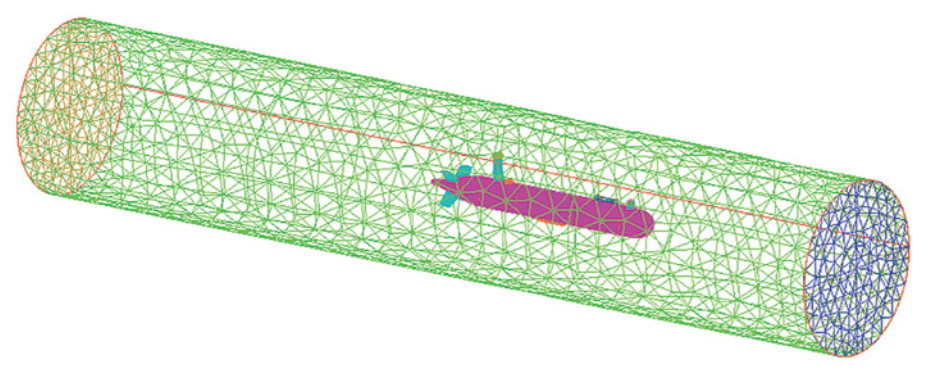 Figure 4 Mesh of the AUV without a propeller
2.5 Nominal wake
The nominal wake distribution is usually used for ship propeller design due to the unavailable effective full-scale wake distribution. In this study, the nominal wake astern the AUV without a propeller was used to design an initial propeller. The nominal wake can be measured at the disc location of the propeller from the towed AUV simulation, which is shown in Figure 5. The nominal wake is a nonuniform inflow to the propeller. It has four quadrants influenced by four rudders and fins. In addition, the four quadrants of the nominal wake are different due to effects from other appendages of the AUV. In the initial propeller design, the average nominal wake at each radius was used, as shown in Figure 6. The average nominal wake increases as the radius increases.
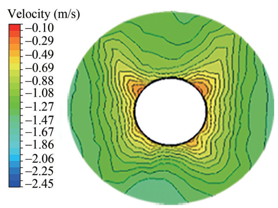 Figure 5 Contour of the axial velocity in the nominal wake
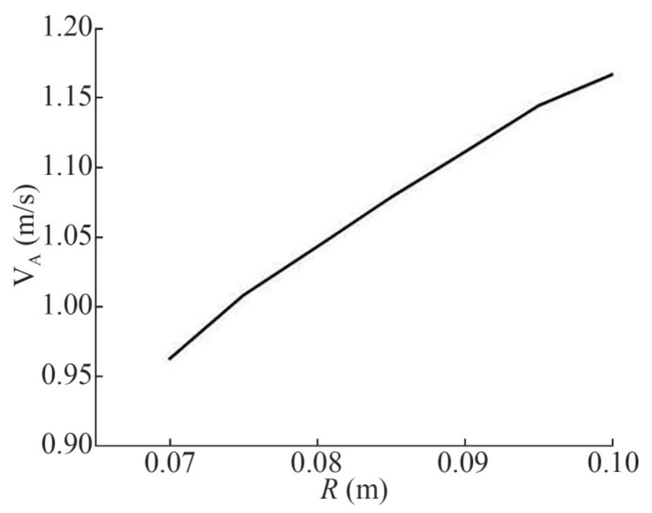 Figure 6 Average nominal wake at different radii
2.6 Design of an initial propeller
After determining the nominal wake, the thrust deduction factor t was estimated to obtain the desired thrust of the propeller. In the OpenProp program interface, the main propeller parameters, such as the blade number, diameter, hub diameter ratio, ship speed, and nominal wake distribution at each radius and desired thrust are inputted, and consequently, a 2D propeller data can be designed. The efficiency of each section was also analyzed, as shown in Figure 7. A radius of 0.6R has the maximum efficiency. By transforming the 2D propeller data to the three-dimensional (3D) data (Wu et al., 2011), a 3D initial propeller (named propeller 1) is obtained.
 Figure 7 Efficiency of each section
3 Open-water test validation
To validate the numerical approach for the self-propulsion of the AUV with a propeller, open-water tests were simulated for the standard propeller (Wu et al., 2019), as shown in Figure 8. The open-water tests were conducted at the water tunnel of Dalian Maritime University. The water tunnel allows a maximum flow velocity of 2.0 m/s. During the open-water tests, the free-stream velocity was set as 0.5 m/s, and the rotation speed was changed from 138 r/min to 1 500 r/min, which resulted in advance coefficients varying from 1 to 0.1. The advance coefficient J = 0 was obtained by setting the inflow velocity at 0 and rotating speed at 1 500 r/min. Measurements were used for comparison with the current simulations, shown in Figure 8. The results show that the numerical results of the open-water test are generally in good agreement with the experimental data over the majority of the propellers' working range.
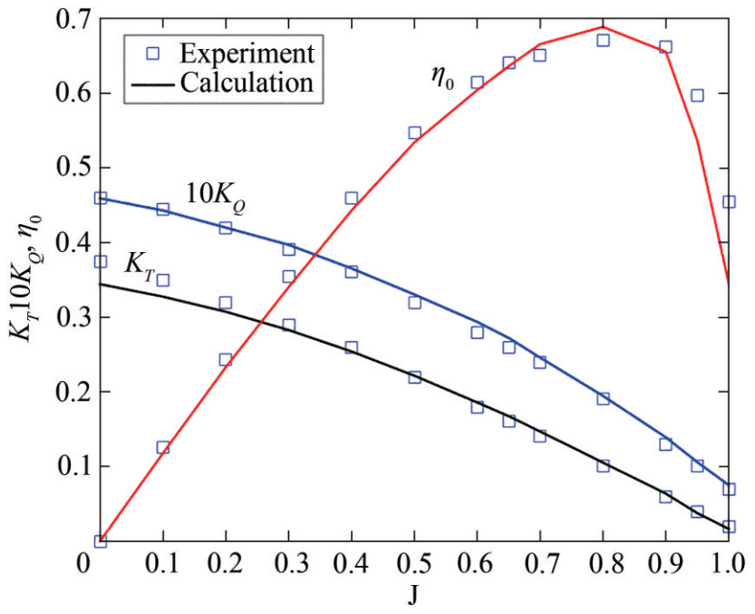 Figure 8 Comparison of the numerical and experimental results in the open-water tests
4 Effective wake
There is a difference between the actual thrust and the desired thrust for the propeller designed by the nominal wake. Sometimes, the propeller designed by the nominal wake cannot obtain the thrust needed to push the ship. This resulted from the difference between the nominal wake and effective wake and the difference between the estimated thrust deduction factor and real thrust deduction factor. Such a difference can be revised by a self-propulsion to obtain the effective wake and real thrust deduction factor. Traditionally, it is impossible to obtain the effective wake for a full-scale ship with a rotating propeller. The effective wake is often measured by particle image velocimetry for a scale ship model in a water tunnel (Ellenrieder and Pothos, 2008; Gui et al., 2001; Jung et al., 2009). In this study, the effective wake from the AUV and propeller interaction was measured through the self-propulsion simulation of the AUV (Wei and Wang, 2013; Carrica et al., 2010; Chase and Carrica, 2013; Sezen et al., 2018; Wang et al., 2017).
Figures 9 and 10 show the axial velocity and tangential velocity just before the propeller interaction, respectively. As can be seen, the effective wake modifies the inflow field and results in upstream wake pre-spiraling by the rotating three-blade propeller. The velocities in the effective wake field have strong non-uniform radial and tangential distributions. The lowest axial velocity occurs near the face surface and the maximum velocity on the back surface of the propeller. To measure the average effective wake at each radius as an input to OpenProp to design a final propeller, different circumferential locations are needed to measure, as shown in Figure 11. Ten radii were selected: 0.4R, 0.45R, 0.5R, 0.6R, 0.65R, 0.7R, 0.8R, 0.9R, 0.95R, and R. The first radius was chosen from 0.4R because the hub radius was 0.38R. At each radius, the disc plane was located at the interaction point between the leading edge and radius, as shown in Figure 11(a). In each disc plane, the axial velocity and tangential velocity were measured at an equal angle interval of 5 degrees, as shown in Figure 11(b). The average measured axial velocity and tangential velocity along the radius are shown in Figure 12. Noticeable differences are observed between the axial velocity for the nominal wake field (Figures 5 and 6) and the effective wake field (Figures 9 and 12). The effective wake is strongly non-uniform due to the pre-swirling effect from the rotating propeller and has a higher average axial velocity than that in the nominal wake.
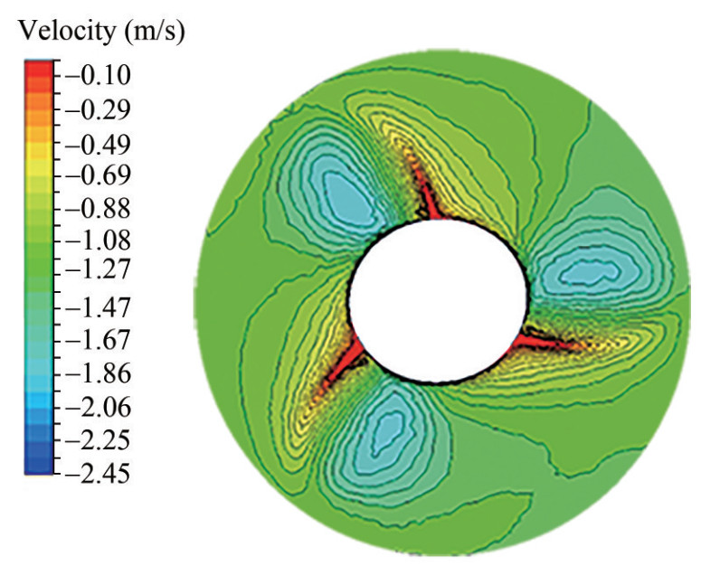 Figure 9 Contour of the axial velocity in the effective wake
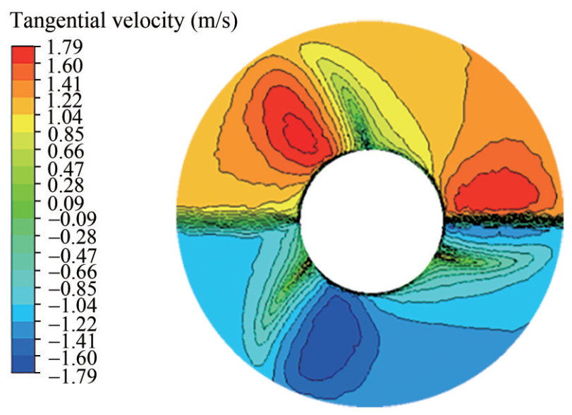 Figure 10 Contour of the tangential velocity in the effective wake
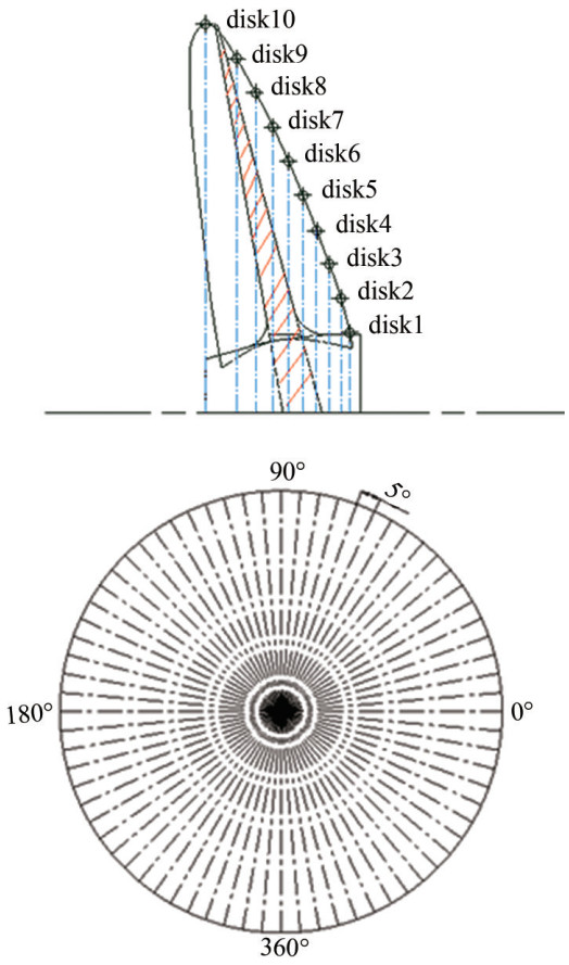 Figure 11 Measurement positions for the effective wake
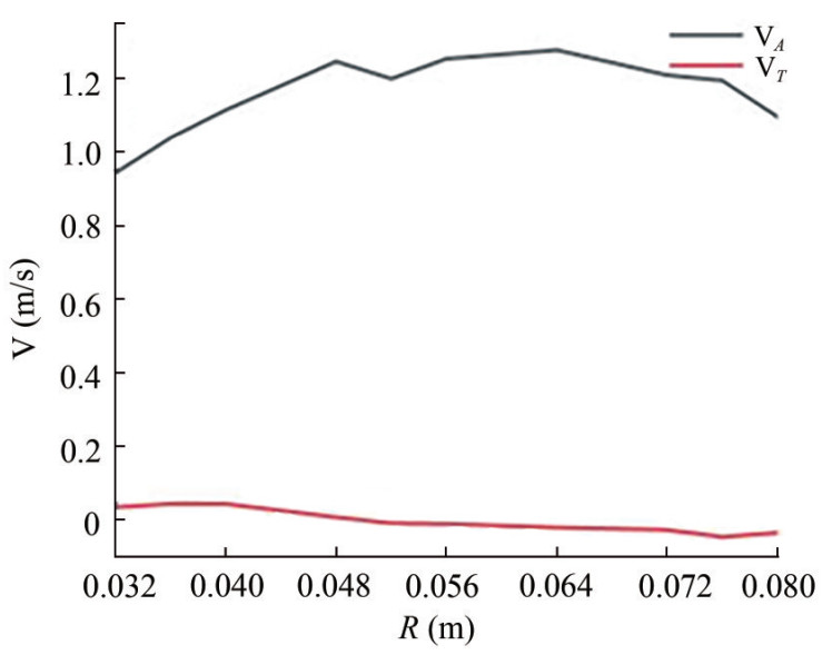 Figure 12 Average effective wake at different radii
5 AUV self-propulsion simulation
The axial velocity and tangential velocity at each radius were inputted into OpenProp, and the thrust deduction factor was recalculated. Then, a new propeller was designed with OpenProp. The main parameters of the designed propeller are shown in Table 1. The 2D data were transformed into 3D one, and a 3D propeller was obtained, as shown in Figure 13 (named propeller 2). The propeller is a threeblade propeller and has a large hub. The hub diameter can be decreased from the view of the high-efficiency propeller design. However, its original value was kept to fit with the AUV and is convenient for comparison between the designed propeller and the original propeller. Then, a threeblade propeller was amounted to the AUV (Figure 14) to conduct the self-propulsion simulation. The mesh for the AUV appended propeller is shown in Figure 15, with the propeller domain having 861 062 meshes. The total number of elements is 3 114 795. The propeller rotation speed was set to 1 000 r/min. By changing the inflow velocity, the curve of the propeller thrust and AUV resistance at the inflow velocity can be calculated (Stefano et al., 2016). The self-propulsion point was determined at the intersection of the two curves at an inflow velocity of 1.481 m/s. In this self-propulsion point, the thrust T, resistance R, and self-propulsion factors, such as the advance ratio J, wake fraction w, and thrust deduction t, can be determined, as shown in Table 2. The thrust deduction factor 1 − t is calculated from Eq. (8), where Rtowed and Rself-propulsion are the resistances in the towed and self-propulsion conditions, respectively.
$$ 1-t=\frac{R_{\text {towed }}}{R_{\text {self - propulsion }}} $$ (8) Table 1 Main parameters of the final propellerD(m) P/D0.7 db/D Z AE/A0 section 0.16 1.0 0.32 3 0.308 NACA65A010 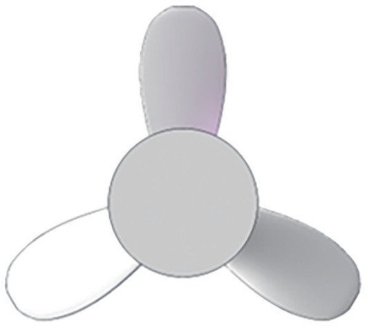 Figure 13 Final designed model (propeller 2)
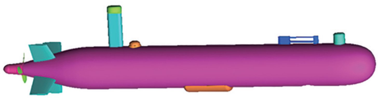 Figure 14 AUV with a propeller and appendages
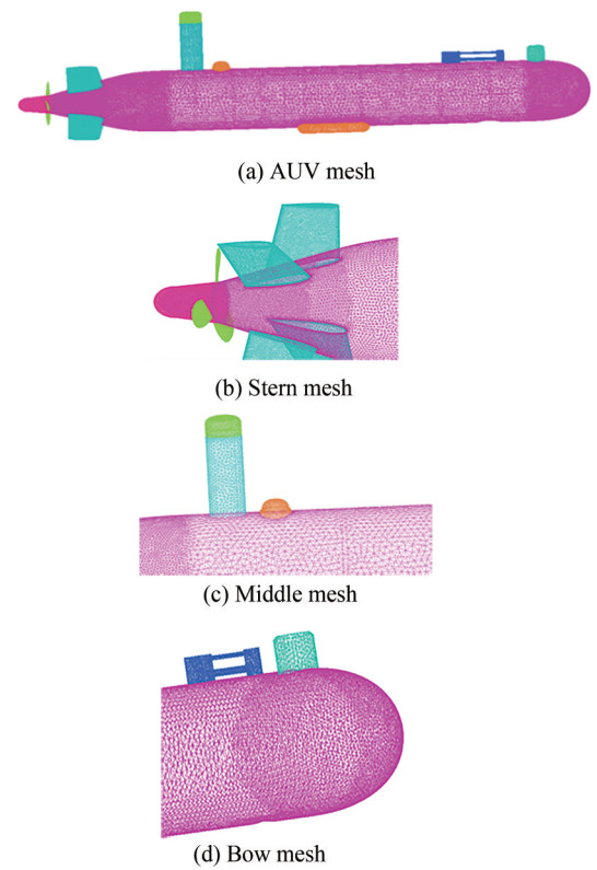 Figure 15 Mesh for the AUV appended by the final designed propellerTable 2 Self-propulsion factors of the AUV appended by the final propeller
n(r/min) T(N) R (N) J w t 1 000 14.351 14.32 0.45 0.19 0.24 The flow fields before and after a propeller interaction are presented to investigate the hydrodynamic characteristics of the propulsion system. Figure 16 shows the velocity contour of the AUV at the self-propulsion point. As can be seen, a boundary layer increases from the AUV bow to the stern. The separating flow from the up-extruding appendage near the AUV's stern highly interacts with the inflow to the propeller, which contributes to the non-uniform inflow to the propeller and thus induces the vibration of the propeller. Tip vortexes are observed downstream of the propeller. Figure 17 shows the pressure contours of the AUV self-propulsion, which shows the high pressure at the AUV's bow and propeller face. In addition, retarded flows were observed at the regions of extruding appendages, which resulted in an increase in the resistance and a non-uniform inflow to the propeller. Figure 18 shows the comparison of the pressure for the final propeller at four slices, two upstream positions (x/R = 0.06, 0), one at the blades (x/R = −0.09) and one downstream of the propeller (x/R = −0.25). The pressure for the propeller blades on the back and face are shown in Figure 19, which also shows a low pressure on the back and high pressure on the face.
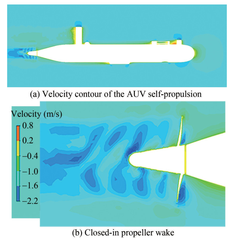 Figure 16 Velocity contours of the AUV self-propulsion with the designed propeller
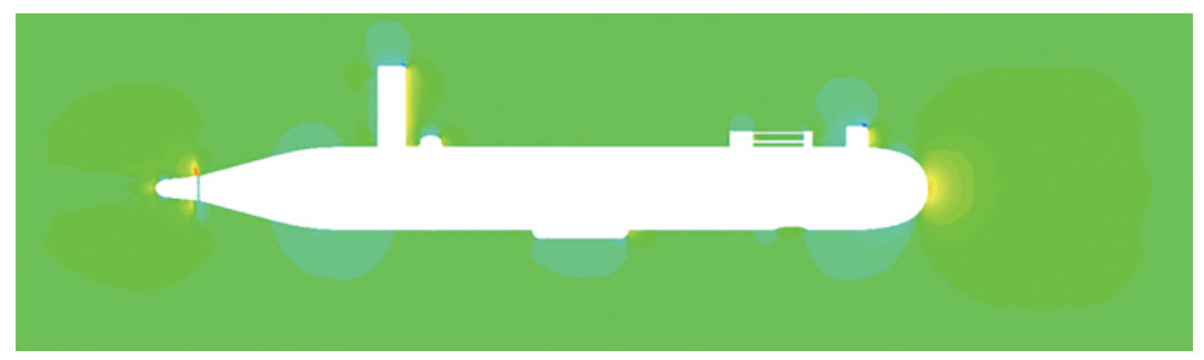 Figure 17 Pressure contours of the AUV self-propulsion with the designed propeller
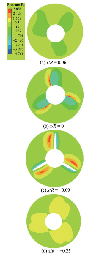 Figure 18 Axial pressure contours for four slices
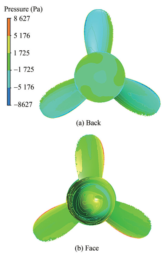 Figure 19 Pressure contours for the back and face surfaces of the propeller blades (propeller 2)
The comparison of the hydrodynamic performance between the designed propellers (propeller 1, designed referring to the nominal wake; propeller 2, referring to the effective wake) and the original propeller is shown in Table 3. At the maximum input torque, the thrust, cruising velocity, and efficiency of the final designed propeller (propeller 2) all improved as compared with those of propeller 1, which are 11.3%, 6.7%, and 2.5%, respectively. The cruising velocity of the designed propeller improved by 21.8%, as compared to that of the original propeller, although not reaching the goal of 3 kn, which is partly due to the large hub diameter needed.
Table 3 Comparison of the propeller performanceName T(N) V(m/s) η Propeller 1 12.897 1.389 0.78 Propeller 2 14.351 1.481 0.8 Original propeller 1.215 Improved (%) (Comparison of Propeller 2 with Propeller 1) 11.3 6.7 2.5 6 Conclusions
A high-efficiency propeller for Explore100 AUV was designed by OpenProp based on the computation of the nominal wake and effective wake. The propeller designed with the effective wake improved its thrust, velocity, and efficiency by approximately 11.3%, 6.7%, and 2.5%, respectively, compared with those with the nominal wake. The cruising velocity of the designed propeller improved by 21.8% compared to the original propeller. The flow survey performed for the towed and self-propulsion simulations of the AUV fully characterizes the behavior of the upstream and downstream flows of the propeller. A non-uniform nominal wake occurred at the propeller plane, which has four quadrants influenced by four rudders and fins. In addition, due to the complex interaction between the AUV and its appendages, there are differences among the quadrants. With the propeller, the effective wake was strongly non-uniform due to the pre-swirling effect from the rotating propeller and had a higher average axial velocity than the nominal wake.
Acknowledgement: We are grateful to the Underwater Vehicle Center of Shenyang Institute of Automation, China, for providing data on the AUV model and its free-running tests. -
Figure 1 Velocity and force distribution on a 2D blade section
Figure 2 Model of the Explorer100 AUV without a propeller
Figure 3 Propeller design flow chart
Figure 4 Mesh of the AUV without a propeller
Figure 5 Contour of the axial velocity in the nominal wake
Figure 6 Average nominal wake at different radii
Figure 7 Efficiency of each section
Figure 8 Comparison of the numerical and experimental results in the open-water tests
Figure 9 Contour of the axial velocity in the effective wake
Figure 10 Contour of the tangential velocity in the effective wake
Figure 11 Measurement positions for the effective wake
Figure 12 Average effective wake at different radii
Figure 13 Final designed model (propeller 2)
Figure 14 AUV with a propeller and appendages
Figure 15 Mesh for the AUV appended by the final designed propeller
Figure 16 Velocity contours of the AUV self-propulsion with the designed propeller
Figure 17 Pressure contours of the AUV self-propulsion with the designed propeller
Figure 18 Axial pressure contours for four slices
Figure 19 Pressure contours for the back and face surfaces of the propeller blades (propeller 2)
Table 1 Main parameters of the final propeller
D(m) P/D0.7 db/D Z AE/A0 section 0.16 1.0 0.32 3 0.308 NACA65A010 Table 2 Self-propulsion factors of the AUV appended by the final propeller
n(r/min) T(N) R (N) J w t 1 000 14.351 14.32 0.45 0.19 0.24 Table 3 Comparison of the propeller performance
Name T(N) V(m/s) η Propeller 1 12.897 1.389 0.78 Propeller 2 14.351 1.481 0.8 Original propeller 1.215 Improved (%) (Comparison of Propeller 2 with Propeller 1) 11.3 6.7 2.5 -
Allston T, Munroe J, Lewis R, Mouland D, Xu J, Walker D (2014) Predicting the wake behind a large AUV hydrofoil. Methods in Oceanography, 1–12. https://doi.org/10.1016/j.mio.2014.07.004 Bellingham JG, Zhang YW, Jonathan E (2010) Efficient propulsion for the Tethys long-range autonomous underwater vehicle. 2010 IEEE/OES. IEEE, Monterey, CA, 1–7 Carrica PM, Castro AM, Stern F (2010) Self-propulsion computations using a speed controller and a discretized propeller with dynamic overset grids. Journal of Marine Science and Technology, 15: 316–330. https://doi.org/10.1016/j.compfluid.2011.07.005 Chase N, Carrica PM (2013) Submarine propeller computations and application to self-propulsion of DARPA Suboff. Ocean Engin eering, 60: 68–80. https://doi.org/10.1016/j.oceaneng.2012.12.029 Ellenrieder V, Pothos KDS (2008) PIV measurements of the asymmetric wake of a two dimensional heaving hydrofoil. Experiments in Fluids, 44: 733–745. https://doi.org/10.1007/s00348-007-0430-z Epagnier KPD, Chung HL, Stanway MJ (2007) An open source parametric propeller design tool. Oceans 2007, Vancouver, BC, Canada, 1–8 Gui L, Longo J, Stern F (2001) Towing tank PIV measurement system, data and uncertainty assessment for DTMB Model 5512. Experiments in Fluids, 31, 336–346. https://doi.org/10.1007/s003480100293 Jung YL, Bu GP, Sang JL (2009) PIV measurements of hull wake behind a container ship model with varying loading condition. Ocean Engineering, 36, 377–385. https://doi.org/10.1016/j.oceaneng.2009.01.006 Kimball, RW, Epps BP, Stanway MJ (2008) OpenProp MATLAB code, http://openprop.mit.edu. Kyung JL, Tetsuji H, Jeung HL (2014) A lifting surface optimization method for the design of marine propeller blades. Ocean Engineering, 88 (472–479). https://doi.org/10.1016/j.oceaneng.2014.07.010 Li L, Zang HW, Wang YH (2017) Autonomous underwater vehicle appearance and propulsion system optimization design. Journal of Machine Design, 34(5): 23–29 (in Chinese). https://doi.org/10.13841/j.cnki.jxsj.2017.05.005 Rao ZQ (2017) A study of hydrodynamic optimization approach of submarine propulsors based on panel method. PhD thesis. Shanghai Jiao Tong University, Shanghai, 54–74 (in Chinese). Regener PB, Mirsadraee Y, Andersen P (2018) Nominal vs. effective wake fields and their influence on propeller cavitation performance. Journal of Marine Science and Engineering, 6(34): 1–14. https://doi.org/10.3390/jmse6020034 Sahili J, Zaidan K (2018) ROV Propellers optimization using CAD design and CFD modeling and experimental validation. 6th RSI International Conference on Robotics and Mechatronics (IcRoM), Tehran, Iran, 418–421. https://doi.org/10.1109/ICROM.2018.8657543 Sezen S, Dogrul A, Delen C, Bal S (2018) Investigation of self-propulsion of DARPA Suboff by RANS mehthod, 150, 258–271. https://doi.org/10.1016/j.oceaneng.2017.12.051 Sheng ZB, Liu YZ (2013) Ship theory (Vol. 2), Shanghai Jiao Tong University Press, Shanghai, China, 160–164 (in Chinese). Stefano G, Juan GA, Mariano PS (2016) Design and analysis of a new generation of CLT propellers. Applied Ocean Research, 59: 424–450. https://doi.org/10.1016/j.apor.2016.06.014 Su YM, Huang S(2013) Ship propeller theory. Harbin Engineering University Press, Harbin, China, 45–90 (in Chinese). Sun WY, Huang GF (2019) Integrated lifting line/Surface panel method for optimal propeller design accounting. for hub effect. Journal of Hydrodynamics, 765–778 (in Chinese). https://doi.org/10.1007/s42241-019-0051-z Wang C, Han K, Sun C, Guo CY (2020) Marine propeller optimization design and parameter analysis. J. Huazhong Univ. of Sci. & Tech. (Natural Science Edition), 48(4): 97–102 (in Chinese). https://doi.org/10.13245/j.hust.200418 Wang JH, Zou L, Wan DC (2017) CFD simulations of free running ship under course keeping control. Ocean Engineering, 141, 450–464 (in Chinese). https://doi.org/10.1016/j.oceaneng.2017.06.052 Wang WQ, Ma KF, Wang SY, Ye LY (2019) Wake-adapted theory design and parameter optimization design of propeller. Applied Science and Technology, 46(5): 1–9 (in Chinese). Wei YS, Wang YS (2013) Unsteady hydrodynamics of blade forces and acoustic responses of a model scaled submarine excited propeller's thrust and side-forces. Journal of Sound and Vibration, 332, 2038–2056 (in Chinese). https://doi.org/10.1016/j.jsv.2012.12.001 Wu LH, Dong LB, Xu WH (2011) 3D Modeling of ship propeller based on MATLAB and ProE. Journal of Dalian Maritime University, 37(2): 17–20 (in Chinese). https://doi.org/10.16411/jxnki.issn1006-7736.2011.02.028 Wu LH, Li YP, Liu KZ, Wang SW, Ai XF, Li S, Feng XS (2019) A physics-based simulation for AUV underwater docking using the MHDG method and a discretized propeller. Ocean Engineering, 187, 106081 https://doi.org/10.1016/j.oceaneng.2019.05.063 Wu LH, Li YP, Su SJ, Yan P, Qin Y (2014) Hydrodynamic analysis of AUV underwater docking with a cone-shaped dock under ocean currents. Ocean Engineering, 85, 110–126. https://doi.org/10.1016/j.oceaneng.2014.04.022 Wu LH, Zhang AF, Li YP, Feng XS, Wang SW (2020) Prediction of autonomous underwater vehicle cruising velocity using a physics-based numerical method. Journal of Harbin Engineering University, 41(2): 194–198 (in Chinese). https://doi.org/10.11990/jheu.201903073 Wu XP, Liu YH, Zhang L (2014) Marine propeller design optimization based on genetic algorithm. Naval Architecture and Ocean Engineering, 4, 31–37 (in Chinese). Zhang RC, Dong XQ, Wang ZY, Huang Y, Yu JC, Yang CJ (2019) Numerical design and validation of propeller for long-range AUV. Shipbuilding of China, 60(1): 141–53 (in Chinese).