Vibration Response Analysis of a New Scientific Research Ship Based on Finite Element Modeling
https://doi.org/10.1007/s11804-022-00272-z
-
Abstract
To control the vibration level of ships under construction, MSC Software's Patran & Nastran modeling solutions can be used to establish a detailed finite element model of a new manned submersible support mother ship based on a line drawing, including the deck layout, bulkhead section, and stiffener distribution. After a comprehensive analysis of the ship simulation conditions, boundaries, and excitation forces of the main operating equipment, modal analysis and calculation of the ship vibration can be conducted. In this study, we calculated and analyzed the vibration response of key points in the stern area of the ship's main deck and the submersible warehouse area under design loading working conditions. We then analyzed the vibration response of typical decks (including the compass deck, steering deck, captain's deck, forecastle deck, and main deck) under the main excitation forces and moments (such as the full swing pod and generator sets). The analysis results showed that under DESIDEP working conditions, the vibration of each deck and key areas of the support mother ship could meet the vibration code requirements of the ship's preliminary design (using the pod excitation and generator sets). Similarly, the vibration response of a scientific research ship under other loading conditions also met the requirements of the code and provided data support for a comprehensive understanding of the ship's vibration and noise levels. Using actual vibration measurements, the accuracy of the vibration level simulations using finite element modeling was verified, the vibration of each area of the ship comfortably meeting the requirements of the China Classification Society.-
Keywords:
- Scientific research ship ·
- Vibration ·
- Modal analysis ·
- Risk assessment ·
- Finite element modeling
Article Highlights• A finite element model is established for a new manned submersible support mother ship based on a line drawing;• The vibration response of key points and typical decks is calculated and analyzed under multi-dynamic excitation taking the ship as an example;• The functional compartments on each deck of the research ship were found to meet the requirements of the CCS com (vib3) by measuring the vibrations in 87 functional compartments;• The results provide a scheme reference for the evaluation and control of vibration and noise of scientific research ships. -
1 Introduction
A scientific research ship (hereinafter, referred to as a research ship) carries scientific and technological personnel and special instruments used to measure and study the natural characteristics of the ocean and obtain related data. A large number of precision scientific instruments are required to work together when a research ship conducts its research. Moreover, the vibration and noise control levels of the ship directly affect the accuracy and effectiveness of such scientific research equipment. Consequently, the vibration and noise control of research ships is a systematic problem. Traditional vibration and noise control methods used in the past cannot meet the requirements of the more stringent vibration and noise indices of modern research ships. Vibration and noise control must be considered throughout the entire design and construction process of modern research ships. The use of finite element simulation software to establish a finite element model of a research ship for simulation and analysis can verify the overall vibration and noise reduction levels of the ship during the design stage, improve the work efficiency, and achieve respectable results.
Research on ship vibration and noise control has a long history, but with the development of China's maritime power, research ships have put forward more stringent research requirements for ship vibration and noise performance as a prerequisite for China to conduct marine scientific research missions. Relevant scholars have done some research. In terms of finite element modeling, Liang et al.(2015) simulated the vibration performance of the engine room by establishing a finite element model, determining the boundary conditions and excitation points, and verifying the accuracy of the simulation method by comparing its results with those experimentally measured. In the modeling process, the engine room is simplified into a box multi cavity structure, which can lay constrained damping materials on the top and bottom of the engine room, it can be used for reference in the modeling of scientific research ship. Wang (2018) and Liu et al. (2021) established a finite element model of a research ship, calculated the ship mode, and compared the frequency of the main excitation force to verify the rationality of the vibration characteristics design of the ship structure. However, the different material densities in different areas are not considered in the modeling, so the change of the center of gravity position of the whole ship affects the modeling accuracy. In terms of the finite element simulation of vibration isolators, Zhu et al. (2014), Yang et al. (2020), and Wang et al. (2018) discussed the design optimization of structural dynamic layouts, geometric parameters, and material parameters by synchronously conducting comprehensive configurations of the stiffness, vibration damping mass, and damping materials.This method can minimize the calculation difficulty of excitation force loading. It is suitable for model simulation analysis of large power plants such as ships.Fang et al.(2014) used auxiliary equipment of different vibration isolation design as the research object to verify the reliability of their method of simplifying the vibration isolator model used to simulate the actual rubber vibration isolator. Therefore, the simulation quality should be considered in the simulation calculation of vibration isolator in this peper.In terms of ship vibration and noise reduction control, Zhou et al. (2019) applied the vibration reduction measures used to control the vibration and noise of mechanical equipment to the power plant of a research ship, comparing the results with the measured data from the ship itself. The research shows that the floating raft vibration isolation system can reduce the ship vibration and noise. In terms of ship incentive force research, Hua and Yu (2017), Ding et al.(2021), Li et al. (2020) studied the relationship between the ship stern excitation and propeller shaft hull system vibration and noise, putting forward a control method for low-frequency vibration and noise control and a simulation method for propeller pulse pressure. These methods can comprehensively analyze the ship excitation source and improve the accuracy of vibration simulation calculation. In terms of evaluating a ship's vibration characteristics, Li et al. (2015) proposed a vibration evaluation method based on vibration tests and dynamic characteristics calculations, and discussed the measures that could be adopted when a forced vibration response calculation could not be carried out in the context of a ship's vibration treatment. Pang et al. (2019) and Gao et al. (2018) proposed the forced vibration characteristics analysis of cylindrical shell structures based on the regional energy decomposition method and Reissner Naghdi's linear thin shell theory, verifying the correctness of this method by comparing its results with those of finite element simulations. At a later stage, research on theradiated underwater noise of research ships was also conducted. Tang et al. (2018) theoretically analyzed and simulated the characteristics of the distance frequency interference fringes of ship noise at different locations in typical deep-sea environments based on the waveguide invariant theory. Li et al. (2018) used the coupled acoustic finite element method (FEM) and far-field automatically matched layer (AML) method, strictly adhering to the acoustic solid coupling dynamic equation and the coupled acoustic indirect boundary element method (IBEM) to calculate the underwater radiated noise of ships in low-frequency domains. Lu et al. (2021) studied underwater radiated noise controling methods for a research ship. Through the vibration analysis of Jiaolong's supporting mother ship, we can understand the vibration level of the ship in the construction stage and avoid construction mistakes. ISO 6954 vibration evaluation standard has been formulated by the technical committee of "mechanical vibration and shock" of the international organization for standardization. ISO 6954-2000 is aimed at the evaluation of human habitability to ships.
Using the new manned submersible support mother ship (Shen Hai Yi Hao) as an example, as shown in Figure 1, Patran and Nastran finite element software applications was used to establish a fine three-dimensional finite element model of the new ship, the modal analysis and vibration calculations being carried out using the FEM. The vibration response of key points in the stern area of the ship's main deck and the submersible warehouse area under DESIDEP working conditions were calculated and analyzed to provide data support for a comprehensive understanding of the ship's vibration level at a later stage, and verify the ship's design efficacy. After completion of the ship's construction, the vibration of each deck and key areas of the ship was measured based on the requirements of the China Classification Society (CCS). The accuracy of the finite element model and simulations was verified through a comparison between the simulations and test measurements, the vibration levels of each area of the ship being low and meeting the requirements of the CCS.
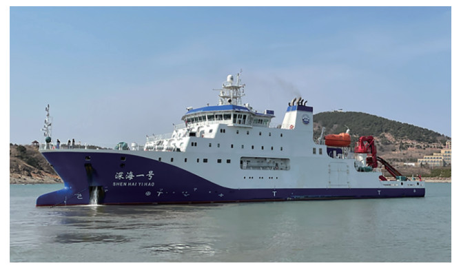 Figure 1 Image of the manned submersible support mother ship
2 Ship parameters and equipment
The manned submersible support mother ship (Shen Hai Yi Hao) is a 4 000 t special support mother ship providing underwater and surface support and maintenance for the deep diving operations of the Jiao Long manned submersible, giving full play to its technical advantages in the fields of deep-sea scientific investigation, seabed resource exploration, and deep-sea biological gene research. The ship can meet the development needs of China's deep-sea industries, its global navigation capabilities, design concept, technical sophistication, and scientific investigation abilities having reached the advanced levels of similar ships around the world. At the design stage, it was proposed that the vibration of each area of the hull should meet the requirements of the CCS com (vib3).
The ship parameters are as follows: 90.2 m in total length, 16.8 m in width, 8.3 m in depth, 4 700 t in displacement, 0.60 m in rib spacing, carrying 60 persons. The ship is equipped with four diesel engines, two full swing pod electric thrusters, and bow thrusters. The main power equipment parameters are shown in Table 1.
Table 1 Parameters of main power equipmentNo. Equipment Name Parameters 1 No. 1 & 2
Main diesel generator setDiesel engine model
Continuous power(kW)
Quantity
Continuous speed (r/min)Wärtsilä 8L26
2 600
2
1 0002 No. 3 & 4
Main diesel generator setDiesel engine model
Continuous power(kW)
Quantity
Continuous speed(r/min)
QuantityWärtsilä 4L20
800
2
1 000
23 Full swing pod electric propulsion Type
Design power(kW)
Propeller diameter(m)
Number of blades
Speed(r/min)Fixed pitch propeller
2 500
3
5
0~3104 Bow thruster Quantity
Design power(kW)
Propeller diameter(m)1
800
1.73 Setting and selection of ship finite element software
The finite element model was established based on a drawing of the ship. The element size was approximately 600 mm, sufficient to establish the structure of each ship rib. The main structure of the model included the outer plate of the hull, deck, and bulkhead (2D shell element simulation), longitudinal, transverse, and vertical trusses (1D beam element simulation), stiffeners (1D beam element simulation), columns between decks (1D tube element simulation), generator set (0d particle element simulation), and oil and water in the cabins (3D solid fluid element simulation). The finite element model of the ship's overall structure is shown in Figure 2.
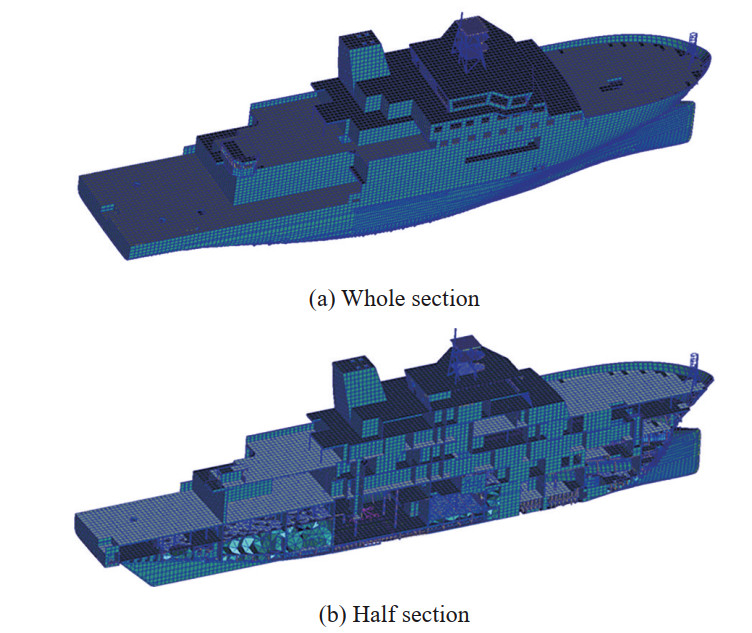 Figure 2 Finite element model of the ship structure
The finite element model was established based on the drawings to keep the weight and center of gravity errors of the hull to within 0.5%. The particle element model was established based on the weight and center of gravity provided by marine, scientific research, and external equipment suppliers. For equipment such as interior decor, piping, electrical, and ventilation equipment, the weight was applied to the corresponding deck area in the form of additional mass. Similarly, deck dressing and damping were applied to the corresponding deck area in the form of additional mass.
The additional mass settings in different areas are summarized in Table 2 based on the purpose of the cabin. The virtual mass method of Nastran's "MFLUID" card is used for simulations, considering the influence of hydrodynamic forces around the hull. Parameters such as the waterline height, fluid density, and position of fluid in the hull outer plate can be adjusted, and the bulk modulus and density of fluids defined. The unit and material properties shown in Table 3 are used for finite element calculations.
Table 2 Additional mass of deck in different areasNo. Ship position Quality setting (kg/m2) 1 Accommodation deck 100 2 Living deck 80 3 Engine room deck 50 Table 3 Setting of unit and material propertiesNo. Parameters Setting 1 Basic parameters Length
Quality
Power
Stress
Speedm
kg
N
Pa
m/s2 Physical parameters of steel Elastic modulus (Pa)
Poisson's ratio
Density(kg/m3)2.1e11
0.3
7 8503 Physical parameters of aluminum alloy Elastic modulus (Pa)
Poisson's ratio
Density(kg/m3)7 e10
0.3
2 7004 Seawater fluid properties Bulk modulus(N/m2)
Density(kg/m3)2.3e9
1 0254 Ship working conditions, boundary selection, and excitation frequency analysis
4.1 Ship working condition and boundary selection
Based on the ship's specifications, the displacement under each design condition is 4 350.9~4 955.4 t. Compared with the ship's total displacement, the displacement difference under each condition and the impact on low-order modes are small. No boundary constraints were imposed during the calculation of whole ship vibration response. Consequently, the model was simulated based on the DESIDEP mode—that is, design loading, 100% consumables, 5.487 m average draft and 4 616.2 t displacement.
4.2 Analysis of ship excitation frequency
The dynamic vibration of the manned submersible support mother ship comes primarily from the full swing pod, generator set, and bow thruster. Table 4 shows the excitation frequency range of the ship's main power equipment. The rated speed of the four diesel generator sets is 1 000 r/min, so they are uniformly described as diesel generator sets in the table, the models not being distinguished.
Table 4 Excitation frequency range of main power equipmentExcitation Excitation frequency (Hz) Limit (Hz) min max Full swing pod 134 r/min Fundamental frequency excitation 2.2 2.0 2.5 Leaf frequency excitation 11.2 10.1 12.3 Full swing pod motor 134 r/min First-order excitation 2.2 2.0 2.5 Second-order excitation 4.5 4.0 4.9 Diesel generator set 1 000 r/min ½ order excitation 8.3 7.5 9.2 First-order excitation 16.7 15.0 18.3 Second-order excitation 33.3 30 36.7 Bow thruster 329 r/min Fundamental frequency excitation 5.5 4.9 6.0 Leaf frequency excitation 21.9 19.7 24.1 Bow thruster motor 1 200 r/min First-order excitation 20.0 18.0 22.0 Second-order excitation 40.0 36.0 44.0 When the mother ship of the manned submersible is in its service navigation state, the bow thruster cannot be used. However, the excitation frequency of the lateral thruster should be considered in modal calculations to prevent local or whole-ship resonance. In vibration response calculations, the full rotation pod and generator set excitation are applied at the corresponding positions, respectively, and the hull vibration response under each excitation is solved using the direct integration method.
4.2.1 Excitation analysis of full swing pod
The full swing pod motor and propeller are integrated underwater. Consequently, the vibration excitation of the hull can be divided into pulsating pressure and motor excitation. The fluctuating pressure acts on the bottom of the hull directly above the full swing pod. In structural areas where the fluctuating pressure of the full swing pod acts, the fluctuating pressure applied on the outer bottom plate of the hull decreases outward from the center. The vertical force spectrum curve of the pod motor excitation is shown in Figure 3 The vibration response of the whole ship can be calculated based on the vertical excitation in the other two directions.
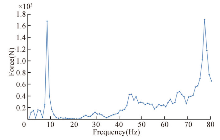 Figure 3 Excitation force spectrum of the pod motor
4.2.2 Excitation analysis of the generator unit
Figure 4 shows the 1–80 Hz vertical force spectrum of the generator unit. The other two directions of the generator set can also be considered based on the vertical excitation to calculate the vibration response of the whole ship.
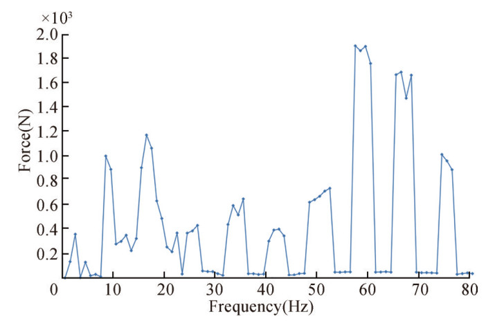 Figure 4 Vertical force spectrum curve of the generator set
5 Calculation and analysis of ship vibration mode
Modal analysis starts with the original parameters, such as the structural characteristics, material characteristics, using the FEM to form a discrete mathematical model of the mass and stiffness matrixes of the whole system, before solving the eigenvalues to determine the modal parameters.
A basic equation representing vibration modal analysis of any system can be expressed as follows:
$$ [\boldsymbol{M}]\{\ddot{\boldsymbol{x}}\}+[\boldsymbol{C}]\{\dot{\boldsymbol{x}}\}+[\boldsymbol{K}]\{\boldsymbol{x}\}=\{f(t)\} $$ (1) where [ M ] is the mass matrix; [C ] is the damping matrix; [ K ] is the stiffness matrix of the system; and {$\ddot{\boldsymbol{x}}$}, {$\dot{\boldsymbol{x}}$} and {x} are the acceleration, velocity, and displacement vectors of the system, respectively.
Equation (2) is the free vibration equation of an undamped system, expressed as follows:
$$ [\boldsymbol{M}]\{\ddot{\boldsymbol{x}}\}+[\boldsymbol{K}]\{\boldsymbol{x}\}=\{0\} $$ (2) For any first-order natural frequency, there must be a corresponding eigenvector{ψ}i corresponding to it, such that:
$$ \left([\boldsymbol{K}]-w_{i}^{2}[\boldsymbol{M}]\right)\{\boldsymbol{\psi}\}_{i}=\{\boldsymbol{0}\} $$ (3) where wi is the ith-order free vibration frequency. This is a typical eigenvalue problem equation, which can solve N number of w2 values and N number of{ψ}i eigenvalues.
Based on the ship's finite element model, the ship vibration modal analysis results can be obtained by loading the excitation sources. The vibration mode calculation results of the whole ship are shown in Table 5.
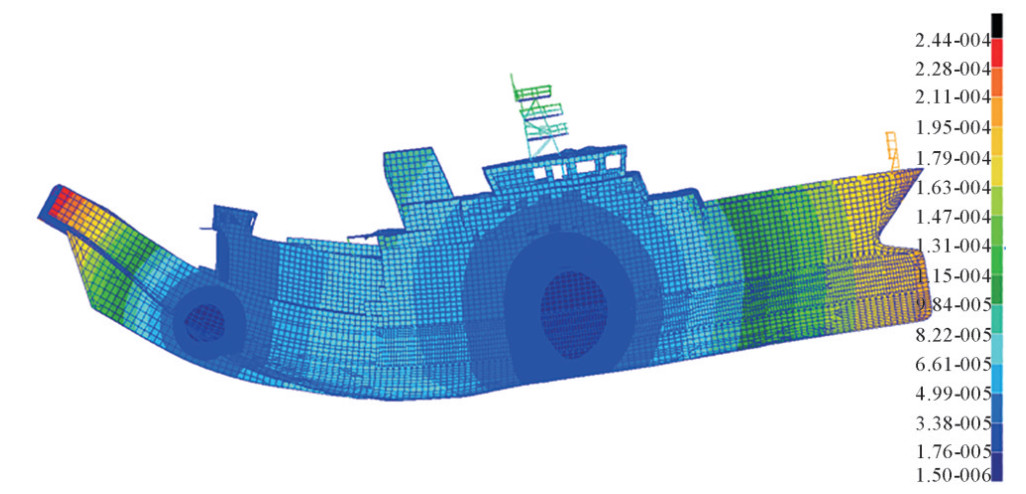 Figure 5 Mode 1 vertical bending vibration f =3.2 Hz
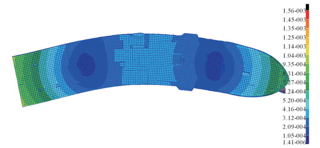 Figure 6 Mode 1 transverse bending vibration f=4.6 Hz
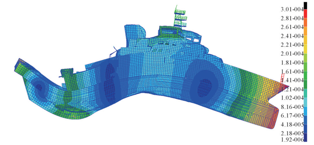 Figure 7 Mode 2 vertical bending vibration f=5.7 Hz
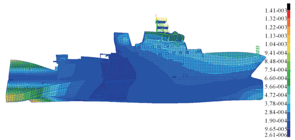 Figure 8 Mode 1 torsional vibration f=6.3 Hz
Comparing the excitation source frequency of the main power equipment of the ship with the low-order modal frequency of the hull (Table 4), it can be established that:
1) The first-order transverse bending modal frequency of the hull (F=4.6 Hz) is within the second-order excitation range of the full rotation pod motor. Considering that the pod motor excitation is small and located underwater, the risk of resonance is low.
2) The second-order vertical bending modal frequency of the hull (F=5.7 Hz) is within the fundamental frequency excitation range of the bow thruster, so there is a risk of resonance under the condition of the bow thruster opening.
6 Vibration response analysis of DESIDEP conditions
6.1 Vibration response analysis of the key points
Based on the requirements of the Design Institute, the vibrations in the tail area of the main deck and the submersible warehouse area require special attention. Consequently, the midship and two side positions of the tail FR0 and the midship position of FR35 were selected as key points to obtain a vibration response under the excitation of the full swing pod and diesel generator set. The four key points are located in the rear area of the main deck, as shown in Figure 9.
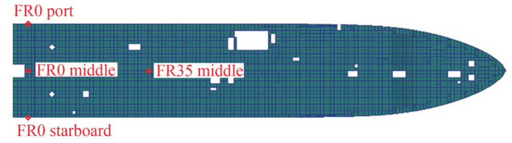 Figure 9 Schematic diagram of selected key points
The vibration at the key points is caused mainly by the excitation of the full swing pod and diesel generator set, as shown in Figures 10 and 11—the maximum vibration of the selected key points caused by the excitation of the full swing pod is 0.55 mm/s, the frequency corresponding to the vibration peak being the double leaf frequency of the full swing pod (22 Hz). When the generator set is installed on the floating raft, the maximum peak vibration velocity at the key points is 0.08 mm/s, the frequency corresponding to the peak vibration velocity being the fundamental frequency of the generator set (17 Hz). The results show that the vibration response meets the specification requirements.
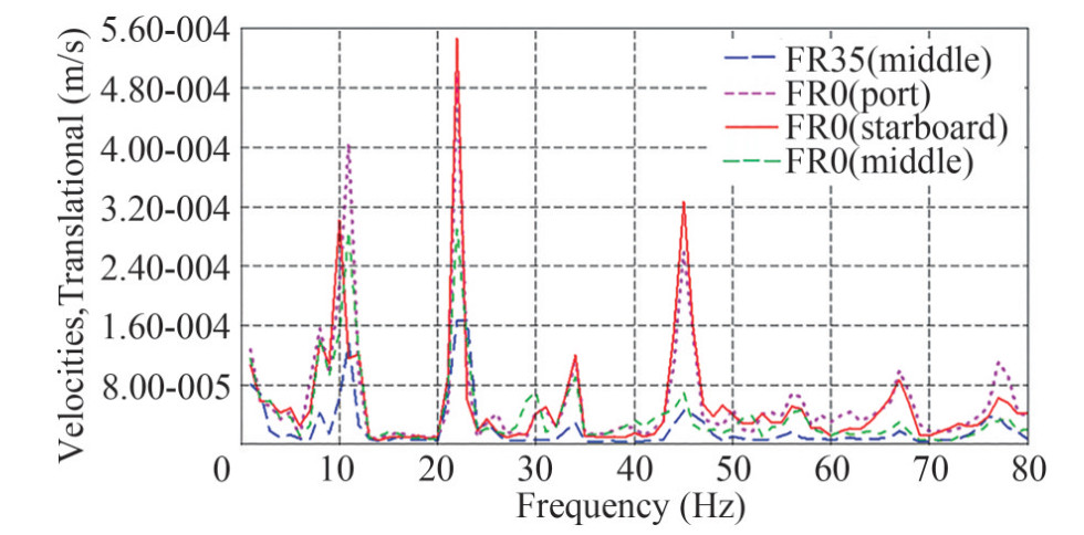 Figure 10 Vibration response spectrum of key points under full swing pod excitation
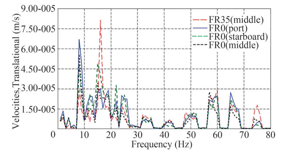 Figure 11 Vibration response spectrum of key points under excitation of generator set
6.2 Vibration response analysis of the decks
As the installation position of precision scientific research equipment and the main activity areas of scientists and crew are all decks, and their vibration is directly reflected by the scientific research equipment and personnel themselves, it is particularly important to study the surface vibration of each deck. Table 6 shows the assessment results of the vibration response of each deck under different excitations (the X-, Y-, and Z-directions are shown, the X-direction being along the longitudinal direction of the hull, the Y-direction being along the transverse direction of the hull, and the Z-direction being along the vertical direction of the hull). It can be seen that under the excitation of the full swing pod and generator sets, the vibration response of each deck meets the specification requirements.
Table 6 Peak results of the vibration response of each deckmm/s No. Deck Limited Peak value of maximum vibration velocity X Y Z 1 Compass 4 0.13 0.08 1.68 2 Drive 4 0.08 0.13 0.90 3 Captain 3.2 0.07 0.07 1.57 4 Boat 3.2 0.07 0.30 0.15 5 Forecastle 3.2 0.08 0.03 1.18 6 Main 3.2 0.08 0.16 1.86 7 Lower 3.2 0.12 0.08 3.92 8 Insole 3.2 0.06 0.11 0.21 The maximum vibration speed of the whole ship is 4.57 mm/s—located at the transverse bulkhead of FR10, the frequency is 22 Hz, and the vibration of this section of the structure is not within the scope of the vibration assessment index of the ship. The distribution diagram of the vibration speed of the whole ship is shown in Figure 12.
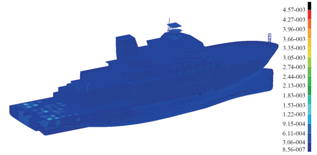 Figure 12 Vibration distribution diagram of the whole ship under excitation of the full swing pod (22 Hz)
6.2.1 Vibration response of the radar mast
Although the vibration level of the ship's radar mast is not within the scope of the CCS vibration assessment of the ship, the radar mast is equipped with many navigational, meteorological, and scientific research instruments, and strong vibrations affect their accuracy. Figure 13 shows the velocity spectrum at the maximum vibration point, the velocity distribution cloud map at the maximum frequency of the vibration velocity in the 1–80 Hz frequency band, and the three-dimensional vibration velocity distribution cloud maps in the X-, Y- and Z-directions, respectively. The vibration of the radar mast is caused mainly by vertical vibrations. The maximum vibration speed is 1.85 mm/s, the excitation frequency being the leaf frequency of the full rotation pod, located at platform C (S-band radar platform). Through calculation, it can be concluded that the vibration of the whole radar mast is small, and there is no need to add vibration and noise reduction measures.
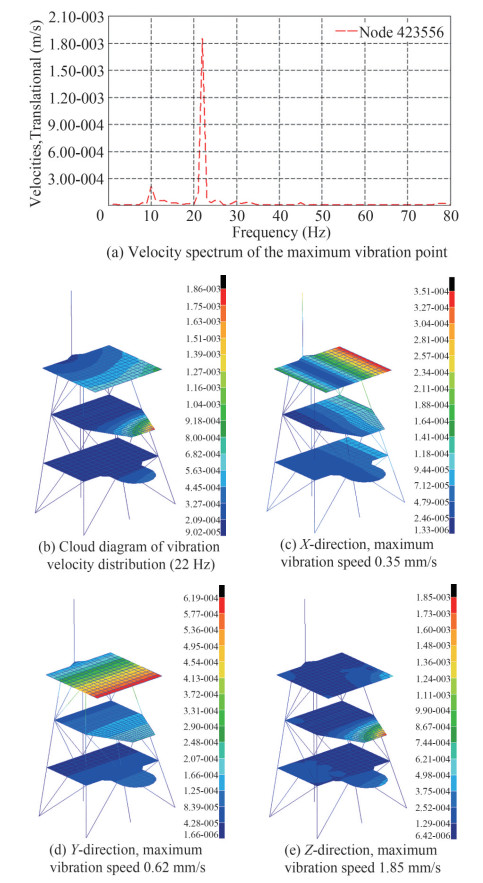 Figure 13 Vibration distribution of the radar mast
6.2.2 Vibration response of the compass deck
Many navigational, meteorological, and scientific research instruments are also arranged on the compass deck. The vibration distribution of the compass deck is shown in Figure 14—that is, the velocity spectrum at the maximum vibration point, the velocity distribution cloud map at the maximum frequency of the vibration velocity in the 1–80 Hz frequency band, and the three-dimensional vibration velocity distribution cloud maps in the X-, Y-, and Z-directions, respectively. The vibration of the compass deck is caused mainly by vertical vibrations. The maximum vibration speed is 1.68 mm/s, located at the starboard side of the bow, and which meets the specification requirements.
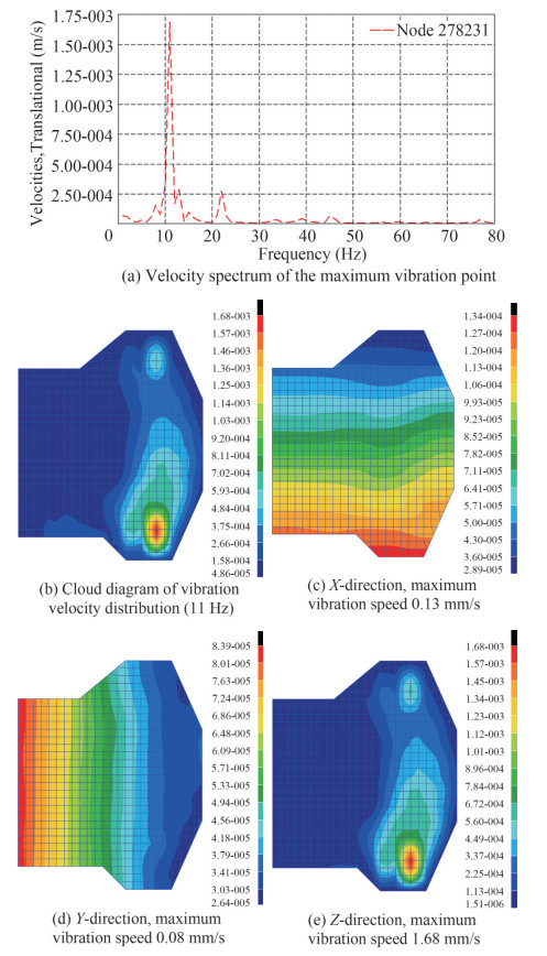 Figure 14 Vibration distribution of the compass deck
6.2.3 Vibration response of the bridge deck
The vibration distribution of the bridge deck is shown in Figure 15—that is, the velocity spectrum at the maximum vibration point, the velocity distribution cloud map at the maximum frequency of the vibration velocity in the 1–80 Hz frequency band, and the three-dimensional vibration velocity distribution cloud maps in the X-, Y-, and Z-directions, respectively. The vibration of the bridge deck is caused mainly by vertical vibrations. The peak value of the maximum vibration velocity is 0.90 mm/s, located at the port side of the cab bow, and which meets the specification requirements.
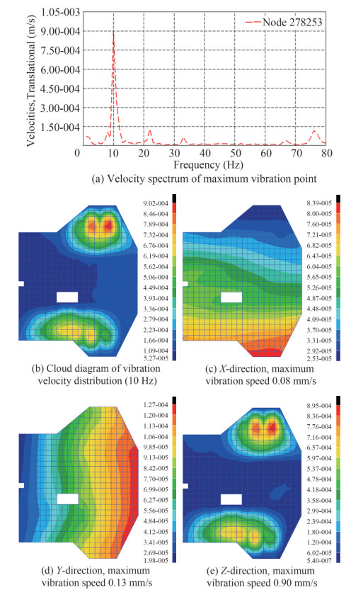 Figure 15 Vibration distribution of the bridge deck
6.2.4 Vibration response of the captain's deck
The vibration velocity distribution of the captain's deck is shown in Figure 16—that is, the velocity spectrum at the maximum vibration point, the velocity distribution cloud map at the maximum frequency of the vibration velocity in the 1–80 Hz frequency band, and the three-dimensional vibration velocity distribution cloud maps in the X-, Y-, and Z-directions, respectively. The vibration of the captain's deck is caused mainly by vertical vibrations. The peak value of the maximum vibration velocity is 1.57 mm/s, located in the captain's cabin, and which meets the specification requirements. The vibration of the captain deck meets the requirements of CCS, and there is no need to reduce vibration and noise locally.
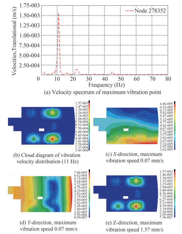 Figure 16 Vibration distribution of the captain's deck
6.2.5 Vibration response of the boat deck
The vibration velocity distribution of the boat deck is shown in Figure 17—that is, the velocity spectrum at the maximum vibration point, the velocity distribution cloud map at the maximum frequency of the vibration velocity in the 1–80 Hz frequency band, and the three-dimensional vibration velocity distribution cloud maps in the X-, Y-, and Z-directions, respectively. The vibration of the boat deck is caused mainly by transverse vibrations. The peak value of the maximum vibration velocity is 0.30 mm/s, located on the deck area of the bow of the hull, and which meets the specification requirements. The vibration of the boat deck meets the requirements of CCS, and there is no need to reduce vibration and noise locally.
 Figure 17 Vibration distribution of the boat deck
6.2.6 Vibration response of the forecastle deck
The vibration velocity distribution of the forecastle deck is shown in Figure 18—that is, the velocity spectrum at the maximum vibration point, the velocity distribution cloud map at the maximum frequency of the vibration velocity in the 1–80 Hz frequency band, and the three-dimensional vibration velocity distribution cloud maps in the X-, Y-, and Z-directions, respectively. The vibration of the forecastle deck is caused mainly by vertical vibrations. The peak value of the maximum vibration velocity is 0.18 mm/s, located in the scientist's room, and which meets the specification requirements. The vibration of the forecastle deck meets the requirements of CCS, and there is no need to reduce vibration and noise locally.
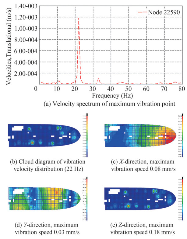 Figure 18 Vibration distribution of the forecastle deck
6.2.7 Vibration response of the main deck
The vibration velocity distribution of the main deck is shown in Figure 19—that is, the velocity spectrum at the maximum vibration point, the velocity distribution cloud map at the maximum frequency of the vibration velocity in the 1–80 Hz frequency band, and the three-dimensional vibration velocity distribution cloud maps in the X-, Y-, and Z-directions, respectively. The vibration of the main deck is caused mainly by vertical vibrations, the excitation frequency being twice the blade frequency of the full rotation pod. The peak value of the maximum vibration velocity is 1.87 mm/s, located in the stern area of the deck, and which meets the specification requirements. The calculated vibration level of each deck meets the requirements of CCS, and there is no need to add additional vibration and noise reduction measures during construction.
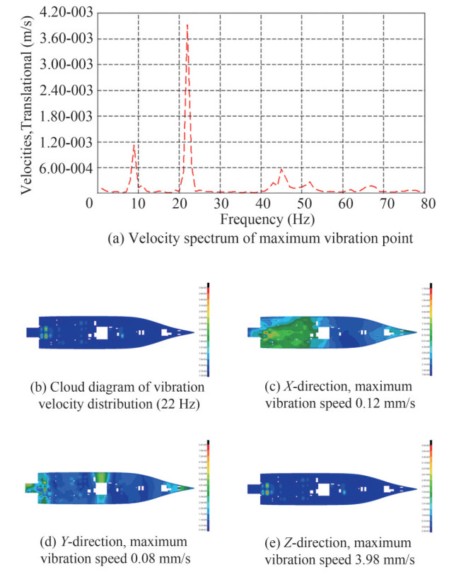 Figure 19 Vibration distribution of the main deck
7 Vibration test and analysis of the whole cabin and deck
To verify the accuracy of this method of analyzing a ship's vibration levels using finite element software simulations before its construction, a vibration test of the whole cabin and deck of the ship after construction was carried out in accordance with the national standards and the requirements of the CCS.
7.1 Test environment and test instruments
For vibration testing under normal DESIDEP conditions, the research ship traveled at 16.6 kn in the East China Sea near Zhoushan; the wind speed was 3.5 m/s, and the wind force and the sea conditions were both Level 3. The test instruments included a three-way accelerometer, signal acquisition and analysis system, and vibration calibrator (Danish B & K).
7.2 Vibration test results
The vibrations in 87 functional compartments were measured, including the ship's steering, captain's, lifeboat, forecastle, main, and lower decks. The total vibration of all decks was the total weighted root mean square value of the three-dimensional speedometer, the total vibration speed (1–80 Hz) being weighted based on the ISO-6954: 2000 standard. The maximum allowable vibration corresponds to a ship comfort Level 3 in the CCS steel marine ship classification code (2018). By means of a comparative analysis, the functional compartments on each deck of the research ship were found to meet the requirements of the CCS com (vib3).
Table 7 Vibration measurement table of typical compartments on some decks of the whole shipmm/s No. Position Measured Calculated Limit 1 503 atmospheric chemistry laboratory 0.2 0.37 4 2 501 cab 0.16 0.37 4 3 Chart area 0.24 0.37 4 4 Bridge deck Reporting area 0.15 0.37 4 5 Look to the left 0.28 0.37 4 6 Right view 0.34 0.37 4 7 Cab outdoor A(rear) 0.29 0.37 4 8 416 scientists 0.24 0.57 3.2 9 414 scientists 0.23 0.57 3.2 10 413 ship Office 0.14 0.57 4 11 412 air conditioner room 0.22 0.57 6.5 12 411 shipowner 0.7 0.57 3.2 13 410 scientists 0.22 0.57 3.2 14 Captain deck 408 electrical equipment room 0.18 0.57 6.5 15 403 third mate 0.3 0.57 3.2 16 406 chief assistant 0.17 0.57 3.2 17 404 VIP 0.16 0.57 3.2 18 405 chief mate 0.5 0.57 3.2 19 402 chief scientist 0.28 0.57 3.2 20 401 Captain 0.18 0.57 3.2 21 4F bow open deck 0.41 0.57 4 22 Emergency generator room 0.17 0.17 6.5 23 331 tail control room 0.23 0.17 6 24 324 laundry 0.35 0.17 4 25 323 air conditioner room 0.19 0.17 6.5 26 322 mechanic B 0.15 0.17 3.2 27 321 infirmary / ward 0.23 0.17 3.2 28 320 mechanic A 0.16 0.17 3.2 29 318 locomotive foreman 0.16 0.17 3.2 30 Lifeboat deck 317 sailor B 0.18 0.17 3.2 31 315 sailor A 0.23 0.17 3.2 32 313 boatswain 0.19 0.17 3.2 33 308 Electrical Engineer 0.2 0.17 3.2 34 311 chef B 0.22 0.17 3.2 35 312 three pipe wheel 0.17 0.17 3.2 36 309 lecture hall 0.18 0.17 4 37 310 second pipe wheel 0.17 0.17 3.2 38 307 chef A 0.15 0.17 3.2 39 306 large pipe wheel 0.17 0.17 3.2 40 305 Chef 0.17 0.17 3.2 41 304 second mate 0.17 0.17 3.2 42 Chief engineer 302 0.27 0.17 3.2 43 301 deep diving Captain 0.48 0.17 3.2 44 3F stern open deck 0.2 0.17 4 45 241 scientists 0.21 0.43 3.2 46 239 scientists 0.26 0.43 3.2 47 237 scientists 0.21 0.43 3.2 48 233 scientists 0.24 0.43 3.2 49 230 air conditioner room 0.22 0.43 6.5 50 229 scientists 0.14 0.43 3.2 51 225 scientists 0.2 0.43 3.2 52 224 engine changing room 0.14 0.43 4 53 223 scientists 0.19 0.43 3.2 54 Entertainment room 221 0.18 0.43 4 55 220 double rooms 0.2 0.43 3.2 56 Forecastle deck 219 mechanic D 0.18 0.43 3.2 57 217 scientists 0.25 0.43 3.2 58 216 double room 0.18 0.43 3.2 59 213 scientists 0.2 0.43 3.2 60 212 superior Restaurant 0.15 0.43 4 61 210 Restaurant 0.18 0.43 4 62 209 mechanic C 0.28 0.43 3.2 63 207 sailor D 0.15 0.43 3.2 64 206 / 208 dishwasher pantry 0.15 0.43 4 65 205 sailor C 0.15 0.43 3.2 66 204 kitchen 0.13 0.43 4 67 232 incinerator room 0.19 0.43 6.5 68 Forecastle deck (rear) 0.26 0.43 4 69 116 Geological Laboratory 0.14 0.7 4 70 115 submersible operation monitoringcenter 0.17 0.7 4 71 117 microbiology laboratory 0.15 0.7 4 72 Main deck 109 data acquisition and processing room 0.16 0.7 4 73 106 air conditioner room 0.16 0.7 6.5 74 Network Center 0.2 0.7 4 75 Stern open working area 0.32 0.7 6.5 76 A29 scientific research storage room 0.7 1.41 4 77 A28 propeller cabin 0.53 1.41 6.5 78 A26 propulsion inverter cabin 0.29 1.41 6.5 79 A23 second winch workshop 0.31 1.41 6.5 80 A19 central control room 0.25 1.41 6 81 Lower deck A15 scientist 0.19 1.41 3.2 82 A13 scientist 0.21 1.41 3.2 83 A12 scientist 0.25 1.41 3.2 84 A11 acoustic equipment room 0.13 1.41 4 85 A08 scientist 0.15 1.41 3.2 86 A06 navigation water Laboratory 0.26 1.41 4 87 A04 gym 0.14 1.41 4 8 Conclusions
In view of the stringent vibration and noise requirements of research ships, this paper proposes a ship modeling approach based on the FEM. Through detailed finite element modeling of a manned submersible support mother ship in the early design stage, modal analysis was conducted, and the vibration responses of all decks and typical areas of the research ship were comprehensively analyzed and evaluated after loading the excitation forces. After completion of the construction, a vibration level test of the entire ship was conducted via a sea trial to verify the accuracy of the finite element simulation results. The main conclusions drawn were as follows:
1) Under DESIDEP load conditions: Under the excitation of the pod and generator set, the vibration of each deck met the vibration index requirements of the manned submersible supporting mother ship.
2) Under other load conditions: The excitation amplitude of the generator set was small, resulting in an insignificant vibration response. The fundamental frequency and blade frequency of the full swing pod were not within the low-order natural frequency range of the whole ship, and could not cause resonance of the ship. The natural frequency of the local structure had little to do with the load, and the vibration response was close to that of this report. Consequently, it can be considered that the vibration response of other load conditions would meet the specification requirements.
3) The vibration levels of deck cabins at all levels of the new research ship were generally low, the vibration of functional cabins on all decks of the research ship meeting the requirements of the CCS com (vib3). The accuracy of the proposed ship finite element model and excitation force calculations during the early design stage were verified, as was the accuracy of the finite element simulation results.
-
Figure 1 Image of the manned submersible support mother ship
Figure 2 Finite element model of the ship structure
Figure 3 Excitation force spectrum of the pod motor
Figure 4 Vertical force spectrum curve of the generator set
Figure 5 Mode 1 vertical bending vibration f =3.2 Hz
Figure 6 Mode 1 transverse bending vibration f=4.6 Hz
Figure 7 Mode 2 vertical bending vibration f=5.7 Hz
Figure 8 Mode 1 torsional vibration f=6.3 Hz
Figure 9 Schematic diagram of selected key points
Figure 10 Vibration response spectrum of key points under full swing pod excitation
Figure 11 Vibration response spectrum of key points under excitation of generator set
Figure 12 Vibration distribution diagram of the whole ship under excitation of the full swing pod (22 Hz)
Figure 13 Vibration distribution of the radar mast
Figure 14 Vibration distribution of the compass deck
Figure 15 Vibration distribution of the bridge deck
Figure 16 Vibration distribution of the captain's deck
Figure 17 Vibration distribution of the boat deck
Figure 18 Vibration distribution of the forecastle deck
Figure 19 Vibration distribution of the main deck
Table 1 Parameters of main power equipment
No. Equipment Name Parameters 1 No. 1 & 2
Main diesel generator setDiesel engine model
Continuous power(kW)
Quantity
Continuous speed (r/min)Wärtsilä 8L26
2 600
2
1 0002 No. 3 & 4
Main diesel generator setDiesel engine model
Continuous power(kW)
Quantity
Continuous speed(r/min)
QuantityWärtsilä 4L20
800
2
1 000
23 Full swing pod electric propulsion Type
Design power(kW)
Propeller diameter(m)
Number of blades
Speed(r/min)Fixed pitch propeller
2 500
3
5
0~3104 Bow thruster Quantity
Design power(kW)
Propeller diameter(m)1
800
1.7Table 2 Additional mass of deck in different areas
No. Ship position Quality setting (kg/m2) 1 Accommodation deck 100 2 Living deck 80 3 Engine room deck 50 Table 3 Setting of unit and material properties
No. Parameters Setting 1 Basic parameters Length
Quality
Power
Stress
Speedm
kg
N
Pa
m/s2 Physical parameters of steel Elastic modulus (Pa)
Poisson's ratio
Density(kg/m3)2.1e11
0.3
7 8503 Physical parameters of aluminum alloy Elastic modulus (Pa)
Poisson's ratio
Density(kg/m3)7 e10
0.3
2 7004 Seawater fluid properties Bulk modulus(N/m2)
Density(kg/m3)2.3e9
1 025Table 4 Excitation frequency range of main power equipment
Excitation Excitation frequency (Hz) Limit (Hz) min max Full swing pod 134 r/min Fundamental frequency excitation 2.2 2.0 2.5 Leaf frequency excitation 11.2 10.1 12.3 Full swing pod motor 134 r/min First-order excitation 2.2 2.0 2.5 Second-order excitation 4.5 4.0 4.9 Diesel generator set 1 000 r/min ½ order excitation 8.3 7.5 9.2 First-order excitation 16.7 15.0 18.3 Second-order excitation 33.3 30 36.7 Bow thruster 329 r/min Fundamental frequency excitation 5.5 4.9 6.0 Leaf frequency excitation 21.9 19.7 24.1 Bow thruster motor 1 200 r/min First-order excitation 20.0 18.0 22.0 Second-order excitation 40.0 36.0 44.0 Table 5 Natural frequency of the whole ship under full load departure conditions
Table 6 Peak results of the vibration response of each deck
mm/s No. Deck Limited Peak value of maximum vibration velocity X Y Z 1 Compass 4 0.13 0.08 1.68 2 Drive 4 0.08 0.13 0.90 3 Captain 3.2 0.07 0.07 1.57 4 Boat 3.2 0.07 0.30 0.15 5 Forecastle 3.2 0.08 0.03 1.18 6 Main 3.2 0.08 0.16 1.86 7 Lower 3.2 0.12 0.08 3.92 8 Insole 3.2 0.06 0.11 0.21 Table 7 Vibration measurement table of typical compartments on some decks of the whole ship
mm/s No. Position Measured Calculated Limit 1 503 atmospheric chemistry laboratory 0.2 0.37 4 2 501 cab 0.16 0.37 4 3 Chart area 0.24 0.37 4 4 Bridge deck Reporting area 0.15 0.37 4 5 Look to the left 0.28 0.37 4 6 Right view 0.34 0.37 4 7 Cab outdoor A(rear) 0.29 0.37 4 8 416 scientists 0.24 0.57 3.2 9 414 scientists 0.23 0.57 3.2 10 413 ship Office 0.14 0.57 4 11 412 air conditioner room 0.22 0.57 6.5 12 411 shipowner 0.7 0.57 3.2 13 410 scientists 0.22 0.57 3.2 14 Captain deck 408 electrical equipment room 0.18 0.57 6.5 15 403 third mate 0.3 0.57 3.2 16 406 chief assistant 0.17 0.57 3.2 17 404 VIP 0.16 0.57 3.2 18 405 chief mate 0.5 0.57 3.2 19 402 chief scientist 0.28 0.57 3.2 20 401 Captain 0.18 0.57 3.2 21 4F bow open deck 0.41 0.57 4 22 Emergency generator room 0.17 0.17 6.5 23 331 tail control room 0.23 0.17 6 24 324 laundry 0.35 0.17 4 25 323 air conditioner room 0.19 0.17 6.5 26 322 mechanic B 0.15 0.17 3.2 27 321 infirmary / ward 0.23 0.17 3.2 28 320 mechanic A 0.16 0.17 3.2 29 318 locomotive foreman 0.16 0.17 3.2 30 Lifeboat deck 317 sailor B 0.18 0.17 3.2 31 315 sailor A 0.23 0.17 3.2 32 313 boatswain 0.19 0.17 3.2 33 308 Electrical Engineer 0.2 0.17 3.2 34 311 chef B 0.22 0.17 3.2 35 312 three pipe wheel 0.17 0.17 3.2 36 309 lecture hall 0.18 0.17 4 37 310 second pipe wheel 0.17 0.17 3.2 38 307 chef A 0.15 0.17 3.2 39 306 large pipe wheel 0.17 0.17 3.2 40 305 Chef 0.17 0.17 3.2 41 304 second mate 0.17 0.17 3.2 42 Chief engineer 302 0.27 0.17 3.2 43 301 deep diving Captain 0.48 0.17 3.2 44 3F stern open deck 0.2 0.17 4 45 241 scientists 0.21 0.43 3.2 46 239 scientists 0.26 0.43 3.2 47 237 scientists 0.21 0.43 3.2 48 233 scientists 0.24 0.43 3.2 49 230 air conditioner room 0.22 0.43 6.5 50 229 scientists 0.14 0.43 3.2 51 225 scientists 0.2 0.43 3.2 52 224 engine changing room 0.14 0.43 4 53 223 scientists 0.19 0.43 3.2 54 Entertainment room 221 0.18 0.43 4 55 220 double rooms 0.2 0.43 3.2 56 Forecastle deck 219 mechanic D 0.18 0.43 3.2 57 217 scientists 0.25 0.43 3.2 58 216 double room 0.18 0.43 3.2 59 213 scientists 0.2 0.43 3.2 60 212 superior Restaurant 0.15 0.43 4 61 210 Restaurant 0.18 0.43 4 62 209 mechanic C 0.28 0.43 3.2 63 207 sailor D 0.15 0.43 3.2 64 206 / 208 dishwasher pantry 0.15 0.43 4 65 205 sailor C 0.15 0.43 3.2 66 204 kitchen 0.13 0.43 4 67 232 incinerator room 0.19 0.43 6.5 68 Forecastle deck (rear) 0.26 0.43 4 69 116 Geological Laboratory 0.14 0.7 4 70 115 submersible operation monitoringcenter 0.17 0.7 4 71 117 microbiology laboratory 0.15 0.7 4 72 Main deck 109 data acquisition and processing room 0.16 0.7 4 73 106 air conditioner room 0.16 0.7 6.5 74 Network Center 0.2 0.7 4 75 Stern open working area 0.32 0.7 6.5 76 A29 scientific research storage room 0.7 1.41 4 77 A28 propeller cabin 0.53 1.41 6.5 78 A26 propulsion inverter cabin 0.29 1.41 6.5 79 A23 second winch workshop 0.31 1.41 6.5 80 A19 central control room 0.25 1.41 6 81 Lower deck A15 scientist 0.19 1.41 3.2 82 A13 scientist 0.21 1.41 3.2 83 A12 scientist 0.25 1.41 3.2 84 A11 acoustic equipment room 0.13 1.41 4 85 A08 scientist 0.15 1.41 3.2 86 A06 navigation water Laboratory 0.26 1.41 4 87 A04 gym 0.14 1.41 4 -
China Classification Society (2018) Code for Classification of Steel Sea Going Ships, China Ding Ning, Gao Zhanfeng, Xiao Yu (2021) Simulation Method of Propeller-Induced Fluctuating Pressure in Ship Vibration Response Calculation. Ship & Boat, 193(4), 37–42. https://doi.org/10.19423/j.cnki.31-1561/u.2021.04.037 Fang Yuanyuan, Xiao Yinglong, Zhang Guohong (2014) Study on vibration reduction characteristics of ship multiunit equipment. Ship & Ocean engineering, 43(2), 146–149. https://doi.org/10.3963/j.issn.1671-7953.2014.02.038 GB/T 7452-2007. ISO 6954 (2000) Mechanical Vibration — Guidelines for Measurement, Reporting and Evaluation of Habitability Vibration of Passenger and Commercial Ships, China Gao Chu, Liu Wenfu, Qu Weiqiang, Chen Lei (2018) Numerical Vibration Analysis of Steel Sandwich Plates with I-shaped Cores. Noise and vibration control, 38(4), 76–80. https://doi.org/10.3969/j.issn.1006-1355.2018.04.015 Hua Hongxing, Yu Qiang (2017) Structural and acoustic response due to excitation from ship stern: overview and suggestions for future research. Chinese Journal of ship research, 12(4): 6–16. https://doi.org/10.3969/j.issn.1673-3185.2017.04.002 Li Qing, Yang Deqing, Yu Yang (2018) Numerical methods for ship underwater sound radiation in low frequency domain with vibroacoustic coupling. Journal of vibration and shock, 37(3): 174–179. https://doi.org/10.13465/jxnki.jvs.2018.03.028 Li Jiasheng, Zhang Zhenguo, Tian Jin (2020) Mechanism of fluid-structure interaction and algorithm for calculating the bearing force of elastic propellers. Journal of vibration and shock, 39(18), 1–10. https://doi.org/10.13465/j.cnki.jvs.2020.18.001 Li Kai, Zhao Deyou, Li Sheng (2015) Diagnosis and treatments for harmful vibration based on the measurement and dynamic computation. Journal of Ship Mechanics, 19(4), 455–461. https://doi.org/10.3969/j.issn.1007-7294.2015.04.014 Liang Bingnan, Yu Hongliang, Cai Yannian (2015) Effect of floating cabins design on vibro-acoustic characteristics of vessel engine room cabins. Ship science and technology, 37(2): 24–29. https://doi.org/10.3404/j.issn.1672-7649.2015.02.005 Liu Zhenzhen, Jiang Guohe, Ge Kunwei (2021) Vibration characteristics of 1 100 m new type of polar exploration cruise. Journal of vibration and shock, 40(46): 212–219. https://doi.org/10.13465/j.cnki.jvs.2021.06.028 Lu Xiaoke, Zou Lirong, Chen Xiaobin, Li Jiangbo (2021) Analysis and application of underwater radiation noise control measures for research vessel, Zaochuan jishu, 14(3): 50–54. https://doi.org/10.12225/j.issn.1000-3878.2021.06.20210610 Pang Fuzhen, Peng Dewei, Li Haichao (2019) Forced vibration characteristics analysis of a cylindrical shell structure. Journal of vibration and shock, 38(16), 7–13. https://doi.org/10.13465/jxnki.jvs.2019.16.002 Tang Shuai, Lan Lianglong, Xu Guojun, Cui Baolong (2018) Research on noise character for moving targets based on deep-ocean waveguide invariant. Journal of Ship Mechanics, 22(7): 888–895. https://doi.org/10.3969/j.issn.1007-7294.2018.07.013 Wang Zhiqiang, Li Xuebin, Huang Lihua (2018) Vibration characteristics of orthotropic circular cylindrical shells based on wave propagation approach and multi-variate analysis. Journal of vibration and shock, 37(7), 227–232. https://doi.org/10.13465/j.cnki.jvs.2018.07.034 Wang Hao (2018) Vibration analysis of the research vessel "Zhang Qian". Noise and vibration control, 38(A1): 156–159. https://doi.org/1006-1355(2018)Z1-0156-04. Yang Deqing, Yang Kang, Wang Bohan (2020) A unified impedance modeling method for ship structural dynamics synthetic layout optimization design. Journal of Vibration Engine ering, 33(3), 485–493. https://doi.org/10.16385/j.cnki.isn.1004-4523.2020.03.006 Zhou Qixue, Mao Qizhi, Ren Jinyu (2019) Application of vibration and noise reduction measures for mechanical equipment of scientific research ship. Ship & Ocean engineering, 48(4): 42–46. https://doi.org/10.3963/j.issn.1671-7953.2019.04.010 Zhu Chenglei, Wei Qiang, Xu Zhiliang (2014) Research on base vibration isolation performance based on finite element dynamic calculation. Ship & Ocean engineering, 43(3): 28–32. https://doi.org/10.3963/j.issn.1671-7953.2014.03.007