A Mathematical Model of a Ship with Wings Propelled by Waves
https://doi.org/10.1007/s11804-021-00221-2
-
Abstract
This paper discusses mathematical modeling of a ship equipped with energy-saving wing devices. Therewith, the ship is mathematically represented by an elongated hull with high-aspect-ratio wings mounted near its bow and stern. Equations, describing ship motions in regular oncoming waves, are written in the spirit of strip theory with account of inertial and damping influence of energy-saving wing elements with the use of linear expansion of wing-related forces with respect to heave and pitch perturbations. This approach readily yields fast numerical solutions for the propulsion of a ship with wings in waves. The latter solutions are then used as an input for calculation of thrust on wing elements on the basis of classical unsteady foil theories corrected for finite aspect ratio. To evaluate speed of the ship in the modes which allow cruising exclusively by wave power, it is hypothetically assumed that in this case, the wave-generated thrust on the wings equals total drag of the ship-plus-wings system, the latter being defined as a sum of its viscous, wave-making, induced (for wing elements) and added-wave components. Excepting the added-wave term and wings' contributions, the total drag is calculated herein by Holtrop method whereas added-wave resistance is evaluated with Beukelman-Gerritsma formula involving kinematic parameters of heaving and pitching motions of the ship calculated both without and with account of the wings. Also discussed in the paper is a decrease of added wave resistance for a ship with wings as compared to that of ship without wings. Finally, the energy efficiency design index (EEDI) introduced by the International Maritime Organization (IMO) is discussed for representative sea conditions as a measure of ship environmental friendliness.-
Keywords:
- Ship motions ·
- Energy-saving wing devices ·
- Wave propulsion ·
- Added resistance ·
- IMO ·
- EEDI
Article Highlights• Mathematical modeling was carried out to study ship motions, added resistance, and EEDI with and without energy-saving wing devices.• The heave and pitch motions, added resistance when using different wings, and their different positions (at the bow, at the stern, and at both extremities) were investigated.• The EEDI and EEDIweather of a ship with and without wings were evaluated based on the approaches suggested by IMO for estimating CO2 emissions of the engine.• The time-averaged thrust of the wing system together with the total drag of ship-plus wings was determined. -
1 Introduction
In recent time, especially during periods of escalating cost of hydrocarbons, there strengthens the interest toward the use of renewable ocean energy, in particular wave power. Another issue of universal importance is climate change which necessitates decrease of the consumption of fossil fuels and volume of harmful engine exhaust of the ship. As shown in this paper, one of the possibilities to reduce the latter is ship propulsion through the use of thrust-generating wings fitted on the hull and intended to harvest renewable wave energy. This path to greener navigation complies with the new, stringent requirements set forth by the International Maritime Organization (IMO) with the goal to drastically reduce harmful exhaust. To evaluate the efficiency of measures protecting the environment, the IMO introduced the energy efficiency design index (EEDI) and proposed recommendations and time schedule of lowering it through design effort. According to the IMO EEDI, ship CO2 emissions should be reduced by 30% in 2025.
Possibly, the first concept of a ship propelled by waves was patented by Linden in 1848 and implemented in a boat named Autonaut (1895) which could move against the waves at a speed of about four knots mostly due to thrust generated by two steel plates, established at the bow and stern. In 1981 Jakobsen designed a propulsion system, generating thrust due to ship motions relative to the water and, conducted tests of a yacht with wings which reportedly was able to save 30% of fuel in headwind waves at a speed of 6 kn. During these tests, the wing had been attached to a spring system adapting its orientation with respect to oncoming flow for thrust generation. With financial support of the Norwegian government, a research fishing vessel with a bulbous bow named Kystfangst of length 20 m and displacement 180 ton was equipped with two wings at the bow with a total reference area about 3 m2 (1985). With significant wave height of 3 m, the wings generated a thrust corresponding to about 8%–16% of the ship drag with account of the struts; therewith, at 4–8 kn, there was observed a decrease of pitching motions at headwind waves and decrease of rolling motions at following seas.
In 1984–1986, Isshiki (1982a, b) and Isshiki and Mitsunori (1983, 1984) investigated similar concept experimentally mounting a bow wing on an 80-m length cargo ship thus demonstrating a possibility of fuel economy albeit noting high cost of equipping ship with such a device. Full-size trials in 1995 of a 174-ton Russian research fishing vessel (see Figure 1) not only confirmed potential savings in engine power, but also revealed simultaneous moderation of longitudinal motions.
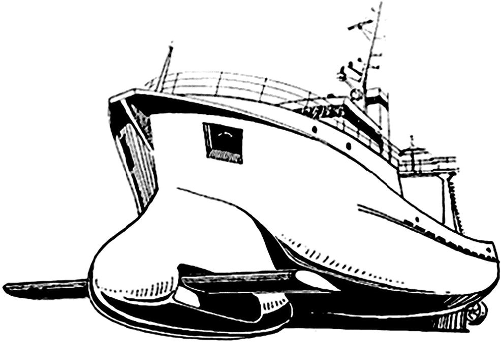 Figure 1 An artist's view of Russian research fishing vessel 174 tons (Nikolaev et al. 1995)
Last year, the Norwegian company "Wavefoil" (2019), based on studies conducted at NTNU (see, Figure 2), carried out full-scale trials of a ship with retractable bow foils on M/F TEISTIN, (see Figure 3), and reported an average fuel savings in the order of 10%.
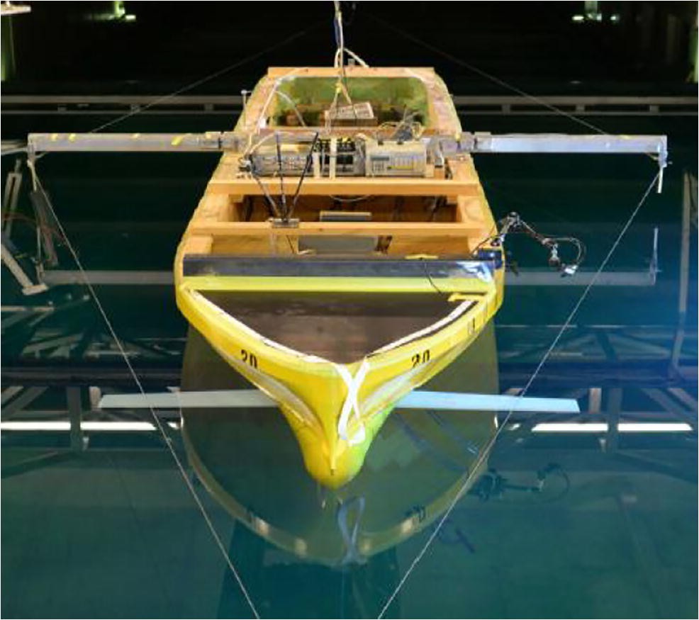 Figure 2 Research model of the Norwegian University of Science and Technology (Bøckmann 2015)
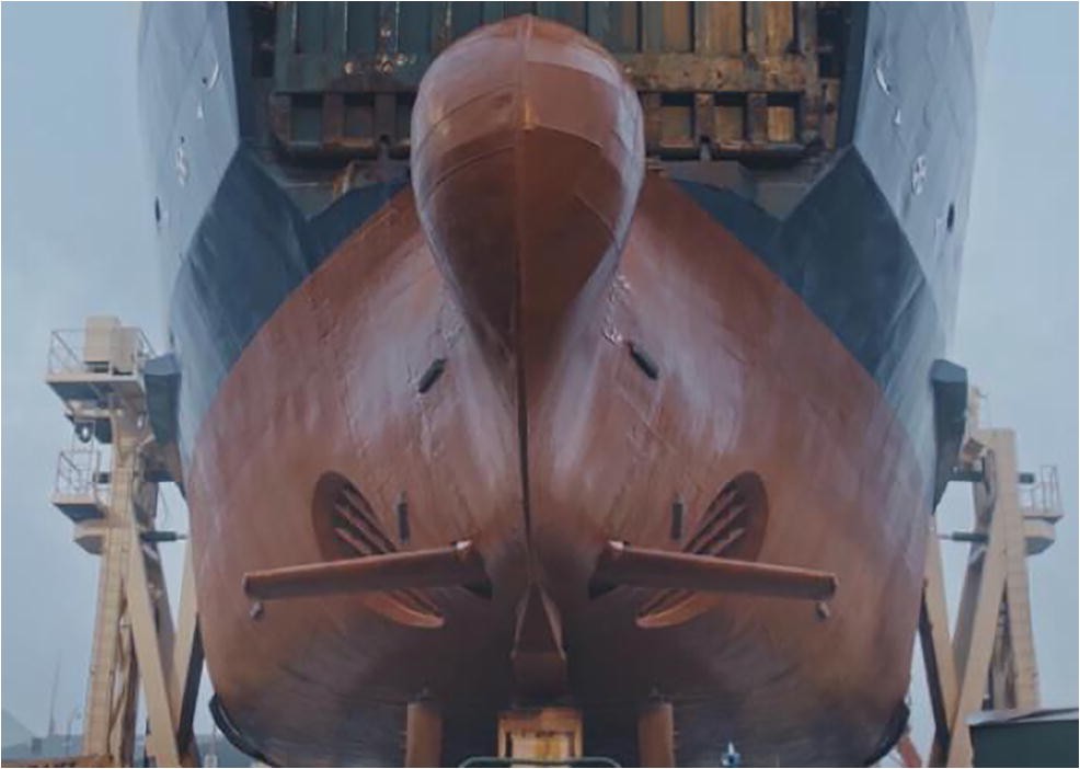 Figure 3 Full-scale experience with retractable bow foils on M/F TEISTIN (Wavefoil 2019)
Quite recently, Wärtsilä and partners have been awarded EU funding for a major project aimed at ship engine and bow wing propulsion innovation systems that when combined, could lead to a 30% reduction in fuel consumption (Wärtsilä 2020), (see Figure 4).
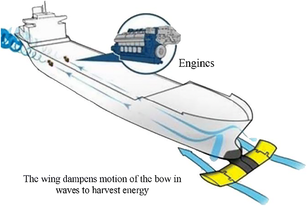 Figure 4 EU-funded project. Combination of ship engine and bow wing propulsion innovation systems (Wärtsilä 2020)
Wave energy-harvesting principle has also been implemented in marine robots exemplified by wave glider (WG) of LiquidRobotics, introduced in 2005–2007, and an USV named AutoNaut of the University of Southampton (2016, see Figure 5). The WG comprises two modules. The upper module is subject to action of waves and transmits its motions through an umbilical to the lower thrust-generating wing module which propels the vehicle, controlled by a rudder fitted on the surface platform.
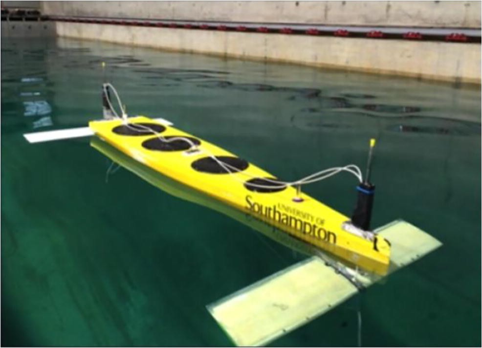 Figure 5 USV AutoNaut of the University of Southampton (Bowker et al. 2016)
Note that at present, the effect of thrust generation by an underwater wing performing heaving and pitching oscillations or subjected to action of vertical gusts induced by orbital motions associated with gravity waves has been sufficiently studied, e.g., see Rozhdestvensky and Ryzhov (2003) review. For the purpose of mathematical modeling, the most widespread is a 2D linear unsteady foil theory represented by classical works of Theodorsen (1935), Garrick (1936), Nekrasov (1947), and Sedov (1966).
Studies of the flapping wing and wing systems as a propulsion device, including the effects of heaving, pitching, and action of vertical gust (due to wave-generated orbital motions of fluid particles) for rigid and elastic wings have been conducted in Rozhdestvensky and Ryzhov (1985), Tyushkevich (1991), Kurapov (1994), Ryzhov (1997), and Rozhdestvensky (2019a, b). Some approaches to mathematical modeling of ships and vehicles equipped with wings related to the problem of moderating wave-induced motions have been published by Kholodilin (1968, 1973), Kholodilin and Shmyrev (1976). A simplified mathematical model of a wave glider type robot was introduced in Rozhdestvensky (2016) where the problem of evaluating the speed of the vehicle is treated for waves of given length in three stages. Firstly, the motions of the upper (displacing) module are considered with account of inertial and damping influence of the lower wing module. The latter influence has been introduced into the equations of heaving motions of the vehicle through the use of expansions with respect to corresponding kinematic parameters. Secondly, with the use of the theory of oscillating foil, the thrust on the lower module is determined. Thirdly, for given system parameters and wave characteristics, an estimation is made of the resulting speed of the WG by equating available thrust with the drag of the vehicle.
Issues of mathematical modeling of ships using wings as propulsion devices were discussed in Eitzen (2012), Eivind (2015), Rozhdestvensky and Zin Min Htet (2019) and Zin Min Htet and Rozhdestvensky (2019a, b, 2020).
A cycle of research works, related to the use of flapping wing propulsion on ships and marine vehicles, has been carried out at Norwegian University of Science and Technology (NTNU). Angvik (2009) in his MS Dissertation employed 2D quasi-stationary approach and, neglecting the reverse influence of the wing foil upon the ship motions, derived some estimates of the effect of the installation of energy-saving wing at the bow of a 94-m length supply ship. Approximate calculations of ship-wing variants with hydrofoils of different lengths for variable wavelength and directions showed a certain perspective for application of a flapping wing propulsion. One particular calculation for the case of regular waves revealed a possibility of moving exclusively due to conversion of wave energy into the thrust of the bow wing device. Borgen (2010) considered potential advantages of a propulsor with an active wing, the latter being defined as a wing, whose incidence varies to maximize the thrust. He conducted a parametric investigation of the margins of fuel savings for three ship types, comprising a supply ship, a coastal tanker, and a small seiner boat and presented calculated data for several hydrofoil configurations varying the heading angles with respect to the wave front and four magnitudes of speed. Based on this data, the author concluded that the fuel savings for the case of irregular waves at speeds 10 and 15 knots constituted more than 60%; this effect increasing with growth of the span and reference area of the wing. Hauge (2013) carried out a detailed analysis of the relevant mathematical modeling, stating in particular that Theodorsen theory works up to unsteady downwash of the order of 70% of the oncoming flow speed. Along with the popular quasi-steady Prandtl lift coefficient finite aspect ratio correction, Hauge discusses a Breslin-Andersen formula for unsteady induced drag in which the lift and induced drag are supposed to be in phase. The author believes that to provide larger incidence, the foil(s) should preferably be located at the bow or the stern closer to the free surface. At the same time, he favors the stern arrangement leaving a possibility to place sea state gauges in the bow region.
The Bøckmann (2015) states a necessity of the hydrofoil incidence control in order to avoid flow separation regimes. The author suggests that in this case, the proper input parameter would be an under-pressure near the foil leading edge. For practical estimation of the boundary of the occurrence of the flow separation, he would install pressure gauges at the foil leading edge and near it. Discussed in the thesis are two methods of foil control: (1) with the use of spring systems and (2) actively controlling the foil incidence by a dedicated motor. It is noted that a disadvantage of the wave hydrofoil with a spring system (used to keep the incidence below separation angle) is due to a necessity of tuning up the spring stiffness in compliance with instantaneous parameters of the wave. Note that for the case of testing without ship model, the hydrofoil without spring system reportedly generated larger thrust than the active one with incidence control. The experiments, conducted in the course of the research under discussion, confirmed a significant role of phase angle between heaving and pitching oscillations at small speeds. Also noted by the author is that the effective phase angle is automatically installed with the use of the hydrofoil with a spring thus making such a foil, in the author's opinion, more preferable than active foil with incidence control. It has been shown that the incidence control based on the pressure gauges readings brings about drag reduction (i.e., increase of the efficiency of wave power conversion into translational ship motion) and, that the maximum fuel savings are reached at headwind waves.
Note that modeling restrictions brought about by foil separation and cavitation occurrence have been discussed in Rozhdestvensky (2019a).
From viewpoint of application for modeling of marine autonomous vehicles employing for their propulsion the springed flapping wings, of interest is a PhD dissertation of Bowker et al. (2016) submitted at Southampton University. Beside issues related to the use of oscillating wings to secure a translational motion, there was an investigation in this thesis, a possibility of additional energy harvesting by means of dampers, transforming wave power into an onboard source of electricity. A hybrid method applied by the author combines determination of time-domain dynamic response of the vehicle to the wave action on the basis of strip theory with two-dimensional sections normal to the waterline plane with simultaneous estimation of electro-mechanical transformation of wave energy through the use of linear generator on permanent magnets. The experimentation was carried out in a wide range of wave lengths both for the cases of headwind and following waves for a self-propelled model, equipped with elastically connected with it wings mounted at the bow and at the stern. In addition to validating numerical results, the experiments showed considerable difference in functioning of the bow and stern wings for headwind and following waves, and confirmed a known theoretical prediction in that the optimal arrangement of the wing consists in placing them at the bow and stern perpendiculars or near those up and downstream (Figure 6).
The purpose of this work being modeling of ships equipped with energy saving wings, we take the following algorithm:
(1) Formulate the problem of determining motions of a ship without wings in waves restricting ourselves to longitudinal motions coupling heave and pitch oscillations;
(2) Complement the equations of motion with terms accounting for the inertial and damping influence of wings and compute motions of the same ship with wing elements;
(3) For calculated motions of ship-plus-wings system, find (time averaged) thrust on the wing system;
(4) Evaluate savings in thrust power due to wave power extraction and obtain an estimation of speed for the case when the ship is able to propel itself entirely on wave power;
(5) Provide an approximate estimation of the Energy Efficiency Design Index and a perspective of reducing its value in compliance with recommendations of the International Maritime Organization.
2 Problem Formulation
2.1 Equations of Longitudinal Motions of a Ship Without and With Wings Due to Action of Waves
To calculate the ship motions we use, following Salvensen et al. (1970), Faltinsen (1990), Blagoveshchenskii and Kholodilin (1975), and Journee and Massia (2001) a strip theory approach, which treats the flow in frequency domain as a combination of 2D, flows in lateral cross sections perpendicular to the ship center-plane.
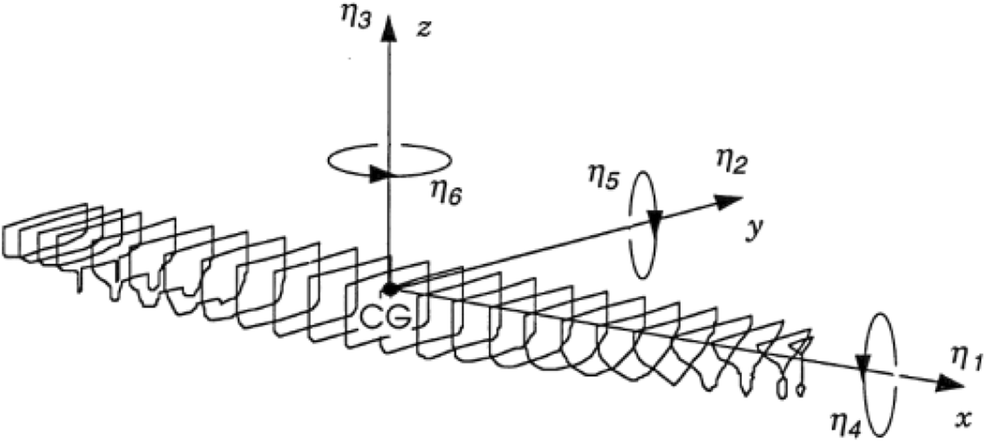
Based on the coordinate system depicted in Figure 7, where for general case the component motions are denoted as η1–surge, η2–heave, η3–pitch, η4–sway, η5–roll, and η6yaw, and restricting the problem formulation to just longitudinal motions, involving coupled heaving and pitching of the ship, we can write coupled equations of longitudinal ship motions, involving heaving, represented by a kinematic parameterη3 and pitching, represented by kinematic parameter η5 as follows:
$$ \left(M+{A}_{33}\right){\ddot{\eta}}_3+{B}_{33}{\dot{\eta}}_3+{C}_{33}{\eta}_3+{A}_{35}{\ddot{\eta}}_5+{B}_{35}{\dot{\eta}}_5+{C}_{35}{\eta}_5={F}_3{e}^{i{\omega}_et} $$ (1) $$ {A}_{53}{\ddot{\eta}}_3+{B}_{53}{\dot{\eta}}_3+{C}_{53}{\eta}_3+\left({I}_5+{A}_{55}\right){\ddot{\eta}}_5+{B}_{55}{\dot{\eta}}_5+{C}_{55}{\eta}_5={F}_5{e}^{i{\omega}_et} $$ (2) where Ajk–added mass coefficients; Bjk–damping coefficients; Cjk–hydrostatic restoring force coefficients; j, ksubscripts (type of motion j, k = 1, 2, …, 6); $ i=\sqrt{-1}, $ ηj–displacements (j = 1, 2, .., 6 represent correspondingly: surge, sway, heave, roll, pitch, and yaw); F3, F5–exciting force and moment; ωe–frequency of encounter; M–mass of the ship; and I–moment of inertia of the ship.
The expressions for inertial, damping, and restoring force coefficients can be found in Salvensen et al. 1970.
$$ {\displaystyle \begin{array}{l}{A}_{33}=\int {a}_{33}\mathrm{d}\xi -\frac{U}{\omega_e^2}{b}_{33}^A\\ {}{A}_{55}=\int {\xi}^2{a}_{33}\mathrm{d}\xi +\frac{U}{\omega_e^2}{A}_{33}^0-\frac{U}{\omega_e^2}{x}_A^2{b}_{33}^A+\frac{U}{\omega_e^2}{x}_A{a}_{33}^A\\ {}{A}_{35}=-\int \xi {a}_{33}\mathrm{d}\xi -\frac{U}{\omega_e^2}{B}_{33}^0+\frac{U}{\omega_e^2}{x}_A^2{b}_{33}^A-\frac{U^2}{\omega_e^2}{a}_{33}^A\\ {}{A}_{53}=-\int \xi {a}_{33}\mathrm{d}\xi +\frac{U}{\omega_e^2}{B}_{33}^0+\frac{U}{\omega_e^2}{x}_A{b}_{33}^A\\ {}{B}_{33}=\int {b}_{33}\mathrm{d}\xi +U{a}_{33}^A\\ {}{B}_{55}=\int {\xi}^2{b}_{33}\mathrm{d}\xi +\frac{U}{\omega_e^2}{B}_{33}^0+{Ux}_A^2{a}_{33}^A+\frac{U}{\omega_e^2}{x}_A{b}_{33}^A\\ {}{B}_{35}=-\int \xi {b}_{33}\mathrm{d}\xi +{UA}_{33}^0-{Ux}_A{a}_{33}^A-\frac{U^2}{\omega_e^2}{b}_{33}^A\\ {}{B}_{53}=-\int \xi {b}_{33}\mathrm{d}\xi -{UA}_{33}^0-{Ux}_A{a}_{33}^A\\ {}{C}_{33}=\rho g\int b\mathrm{d}\xi \\ {}{C}_{55}=\rho g\int {\xi}^2b\mathrm{d}\xi \\ {}{C}_{35}={C}_{53}=-\rho g\int \xi b\mathrm{d}\xi \end{array}} $$ When the ship is equipped with wings, the latter produce inertial and damping impact on the ship which has to be accounted for in the equations of motion. Prior to introducing wing terms into the coupled equations of longitudinal motions, we have to discuss the ways of determining of hydrodynamic characteristics of (energy saving) wings which are intended to convert the wave power into translational motion of the ship. The wings of interest in the mathematical model under discussion have sufficiently large aspect ratio and are fixed in the vicinity of the bow or/and stern of the ship. Adding them up to the mathematical model, we have to know their unsteady lift, moment, and thrust coefficients. In what follows, we neglect hydrodynamic interaction of these wings with the hull and free surface. As justified by the assumption of large aspect ratio, we are basically using unsteady 2D foil theory and account for finite aspect ratio through Prandtl-type corrections.
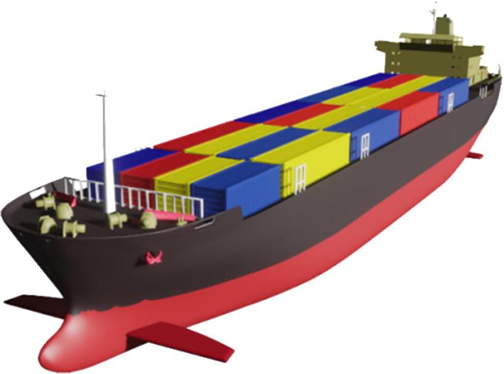
The schematics of wavy flow past a ship equipped with energy-saving wings is shown in Figure 8. The ship with fore and aft wings is shown in Figure 9.
Equations (1) and (2) reflect longitudinal (heaving and pitching) motions of a ship without wings. In what follows, we extend our formulation to the case of the ship equipped with wings fitted on the ship bottom at the bow and stern extremities. To do that, we first add in the right-hand sides of the equations the inertial and damping forces acting on the ship due to the wings. As these forces are proportional to the unknown velocity and acceleration of heaving motions $ \left({\dot{\eta}}_3,{\ddot{\eta}}_3\right) $and to the unknown pitching angles and their angular velocities $ \left({\eta}_5,{\dot{\eta}}_5\right) $, the corresponding terms are transferred to the left-hand sides of the equations (1) and (2) and eventually lead to the new equations (3)–(4), accounting for the influence of wings upon longitudinal motions of the ship. Note that additionally, there are added in the right-hand sides wing-related terms accounting for the forces on the wings due to orbital motions of fluid particles in the wave (vertical gust). Based on the aforementioned considerations and the results for unsteady forces acting on the wings in the case of heaving, pitching, and action of the vertical gust, we can derive the final equations of the coupled heave and pitch motion of the ship with wing devices in the form
$$ \begin{array}{*{20}{l}} \begin{array}{l} \left( {M + {A_{33}} + {A_{33,{\rm{wing}}}}} \right){{\ddot \eta }_3} + \left( {{B_{33}} + {B_{33,{\rm{wing}}}}} \right){{\dot \eta }_3} + {C_{33}}{\eta _3}\\ \ + \left( {{A_{35}} + {A_{35,{\rm{wing}}}}} \right){{\ddot \eta }_5} + \left( {{B_{35}} + {B_{35,{\rm{wing}}}}} \right){{\dot \eta }_5} \end{array}\\ \begin{array}{l} \ + \left( {{C_{35}} + {C_{35,{\rm{wing}}}}} \right){\eta _5}\\ \ = {F_3}{e^{i{\omega _e}t}} + {F_{3W,{\rm{wing}}}} \end{array} \end{array} $$ (3) $$ \begin{array}{l} \left( {{A_{53}} + {A_{53,{\rm{wing}}}}} \right){{\ddot \eta }_3} + \left( {{B_{53}} + {B_{53,{\rm{wing}}}}} \right){{\dot \eta }_3} + {C_{53}}{\eta _3}\\ \ + \left( {{I_5} + {A_{55}} + {A_{55,{\rm{wing}}}}} \right){{\ddot \eta }_5} + \left( {{B_{55}} + {B_{55,{\rm{wing}}}}} \right){{\dot \eta }_5}\\ \ + \left( {{C_{55}} + {C_{55,{\rm{wing}}}}} \right){\eta _5}\\ \ = {F_5}{e^{i{\omega _e}t}} + {F_{5W,{\rm{wing}}}}, \end{array} $$ (4) where, for the bow wing (−xf) of the aspect ratio Λ, the chord c and the spans, the terms, accounting for the influence of the wings, have been derived as
$$ \begin{array}{l} {A_{33,b{\rm{wing}}}} = c_z^{{{\ddot \eta }_3}}\rho \pi {\left( {\frac{c}{2}} \right)^2}s,\\ {B_{33,b{\rm{wing}}}} = c_z^{{{\dot \eta }_3}}\rho \frac{U}{{2\left( {1 + \frac{2}{\Lambda }} \right)}}cs,\\ {B_{35,b{\rm{wing}}}} = - {x_f}{B_{33,b{\rm{wing}}}} - c_z^{{{\dot \eta }_5}}\rho \pi U{\left( {\frac{c}{2}} \right)^2}s,\\ {C_{33,b{\rm{wing}}}} = 0,\\ {A_{35,b{\rm{wing}}}} = {A_{53,b{\rm{wing}}}} = - {x_f}{A_{33,b{\rm{wing}}}},\\ {C_{35,b{\rm{wing}}}} = - c_z^{{\eta _5}}\rho \frac{{{U^2}}}{{2\left( {1 + \frac{2}{\Lambda }} \right)}}cs,\\ {A_{55,b{\rm{wing}}}} = x_f^2{A_{33,b{\rm{wing}}}},\\ {B_{53,b{\rm{wing}}}} = - {x_f}{B_{33,b{\rm{wing}}}},\\ {C_{53,b{\rm{wing}}}} = 0,\\ {B_{55,b{\rm{wing}}}} = x_f^2{B_{33,b{\rm{wing}}}} + c_z^{{{\dot \eta }_5}}\rho \pi {\left( {\frac{c}{2}} \right)^2}U{x_f}s,\\ {C_{55,b{\rm{wing}}}} = {C_{35,b{\rm{wing}}}}{x_f},\\ {F_{3W,b{\rm{wing}}}} = \left[ {\left( { - \rho Ucs\frac{{{\omega _O}{\zeta _A}{e^{k{z_f}}}{e^{ - ik{x_f}}}}}{{2\left( {1 + \frac{2}{\Lambda }} \right)}}c_z^W} \right) - \left( {\rho \pi \frac{{{\omega _o}{\omega _e}{\zeta _a}{e^{k{z_f}}}{c^2}s{e^{ik{x_f}}}}}{4}c_z^{\dot W}} \right)} \right]{e^{i{\omega _e}t}},\\ {F_{5W,b{\rm{wing}}}} = - {x_f}\left[ {\left( { - \rho Ucs\frac{{{\omega _O}{\zeta _A}{e^{k{z_f}}}{e^{ - ik{x_f}}}}}{{2\left( {1 + \frac{2}{\Lambda }} \right)}}c_z^W} \right) - \left( {\rho \pi \frac{{{\omega _o}{\omega _e}{\zeta _a}{e^{k{z_f}}}{c^2}s{e^{ - ik{x_f}}}}}{4}c_z^{\dot W}} \right)} \right]{e^{i{\omega _e}t}}. \end{array} $$ (5) For stern wing (xf) of the aspect ratio Λ, the chord c and the span s, the terms, accounting for the influence of the wings, have been derived as
$$ \begin{array}{l} {A_{33,s{\rm{wing}}}} = c_z^{{{\ddot \eta }_3}}\rho \pi {\left( {\frac{c}{2}} \right)^2}s,\\ {B_{33,s{\rm{wing}}}} = c_z^{{{\dot \eta }_3}}\rho \frac{U}{{2\left( {1 + \frac{2}{\Lambda }} \right)}}cs,\\ {C_{33,s{\rm{wing}}}} = 0,{C_{53,s{\rm{wing}}}} = 0,{C_{55,b{\rm{wing}}}} = - {C_{35,b{\rm{wing}}}}{x_f},\\ {A_{35,s{\rm{wing}}}} = {A_{53,s{\rm{wing}}}} = {x_f}{A_{33,s{\rm{wing}}}},\\ {B_{35,s{\rm{wing}}}} = {x_f}{B_{33,s{\rm{wing}}}} - c_z^{{{\dot \eta }_5}}\rho \pi U{\left( {\frac{c}{2}} \right)^2}s,\\ {C_{35,s{\rm{wing}}}} = - c_z^{{\eta _5}}\rho \frac{{{U^2}}}{{2\left( {1 + \frac{2}{\Lambda }} \right)}}cs,\\ {A_{55,s{\rm{wing}}}} = x_f^2{A_{33,s{\rm{wing}}}},{B_{53,s{\rm{wing}}}} = {x_f}{B_{33,s{\rm{wing}}}},\\ {B_{55,b{\rm{wing}}}} = x_f^2{B_{33,b{\rm{wing}}}} - c_z^{{{\dot \eta }_5}}\rho \pi {\left( {\frac{c}{2}} \right)^2}U{x_f}s,\\ {F_{3W,s{\rm{wing}}}} = \left[ {\left( { - \rho Ucs\frac{{{\omega _O}{\zeta _A}{e^{k{z_f}}}{e^{ - ik{x_f}}}}}{{2\left( {1 + \frac{2}{\Lambda }} \right)}}c_z^W} \right) - \left( {\rho \pi \frac{{{\omega _o}{\omega _e}{\zeta _a}{e^{k{z_f}}}{c^2}s{e^{ - ik{x_f}}}}}{4}c_z^{\dot W}} \right)} \right]{e^{i{\omega _e}t}},\\ {F_{5W,s{\rm{wing}}}} = {x_f}\left[ {\begin{array}{*{20}{l}} {\left( { - \rho Ucs\frac{{{\omega _O}{\zeta _A}{e^{k{z_f}}}{e^{ - ik{x_f}}}}}{{2\left( {1 + \frac{2}{\mathit{\Lambda }}} \right)}}c_z^W} \right)}\\ { - \left( {\rho \pi \frac{{{\omega _o}{\omega _e}{\zeta _a}{e^{k{z_f}}}{c^2}s{e^{ - ik{x_f}}}}}{4}c_z^{\dot W}} \right)} \end{array}} \right]{e^{i{\omega _e}t}}. \end{array} $$ (6) where U is speed of the ship, 1/(1 + 2/ Λ) is a Prandtl lifting line theory correction for finite aspect ratio Λ, and the foil submergence depth zf = − d.
Note that complying with axes system adopted herein, the notations for wing hydrodynamic derivatives, obtained in previous works, have been re-denoted correspondingly. For example, the derivatives obtained as $ {C}_y^{\dot{h}},{C}_y^{\ddot{h}},{C}_y^{\theta },{C}_y^{\dot{\theta}} $ in traditional wing theory approach were replaced herein by $ {C}_z^{{\dot{\eta}}_3},{C}_z^{{\ddot{\eta}}_3},{C}_z^{\eta_5},{C}_z^{{\dot{\eta}}_5}. $
With the afore-introduced notations, we employ in calculations the following wing characteristics borrowed from Rozhdestvensky and Ryzhov (1985), Tyushkevich (1991), and Rozhdestvensky (2016). In the calculations, we assumed a0 = 0.
For heaving motions,
$$ \begin{array}{l} {a^{{{\dot \eta }_3}}} = - 2F\left( {{k_a}} \right),{a^{{{\ddot \eta }_3}}} = \frac{{ - 2G\left( {{k_a}} \right)}}{{{k_a}}},c_z^{{{\dot \eta }_3}} = - 2\pi F\left( {{k_a}} \right),c_z^{{{\ddot \eta }_3}}\\ \ = \frac{{ - 2\pi }}{{{k_a}}}\left[ {G\left( {{k_a}} \right) + \frac{{{k_a}}}{2}} \right], \end{array} $$ (7) For pitching motions,
$$ \begin{aligned} &a^{\eta_{5}}=2\left[F+k_{a}\left(a_{o}-^1{/_2}\right) G\right] \text {, }\\ & \ \ \ \ \ \ \ \ \ \ \ \ \ \ \ \ \ \ \ \ a^{\eta_{5}}\\ &=2\left[\frac{G}{k_{a}}-F\left(a_{o}-^1{/_2}\right)-\frac{1}{2}\right], c_{z}^{\eta_{5}}\\ &=2 \pi\left[F+k_{a} G\left(a_{o}-^1{/_2}\right)+\frac{k_{a}^{2} a_{o}}{2}\right], c_{z}^{\eta_{5}}\\ &=2 \pi\left[\frac{G}{k_{a}}-F\left(a_{o}-^1{/_2}\right)+\frac{1}{2}\right], \end{aligned} $$ (8) For the vertical harmonic gust effect, associated with influence of orbital motion of fluid particles on characteristics of the wings
$$ {\displaystyle \begin{array}{l}{a}^W=\frac{2}{k_a}\left[{J}_0G-{J}_1F-{J}_1\right],\\ {}{a}^{\dot{W}}=2\left[{J}_0F+{J}_1G\right],{c}_z^W=2\pi \left[{J}_0F+{J}_1G\right],\\ {}{c}_z^{\dot{W}}=\frac{2\pi }{k_a}\left[{J}_0G-{J}_1F+{k}_a{J}_0-{J}_2\right],\end{array}} $$ (9) where $ {k}_a=\frac{\omega_ec}{2U}- $ Strouhal number based on the circular frequency of a non-stationary perturbation, F(ka), G(ka)−real and imaginary parts of the Theodorsen function, J0(ka), J1(ka), J2(ka), J3(ka)−Bessel functions.
3 Calculated Results for a Container Ship with and Without Wings
Calculations for a ship without and with energy-saving wings are exemplified for a container ship of S − 175 type, whose general data (see Table 1) as well as length-wise integrated inertial, damping, and restoring characteristics were borrowed from the ITTC (1978) and Murdey (1978) publications. Wing parameters used in the calculations are shown in Table 2.
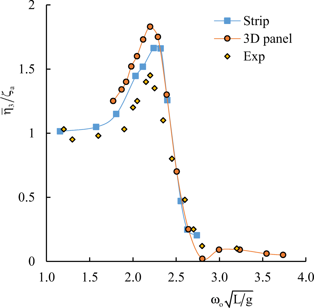
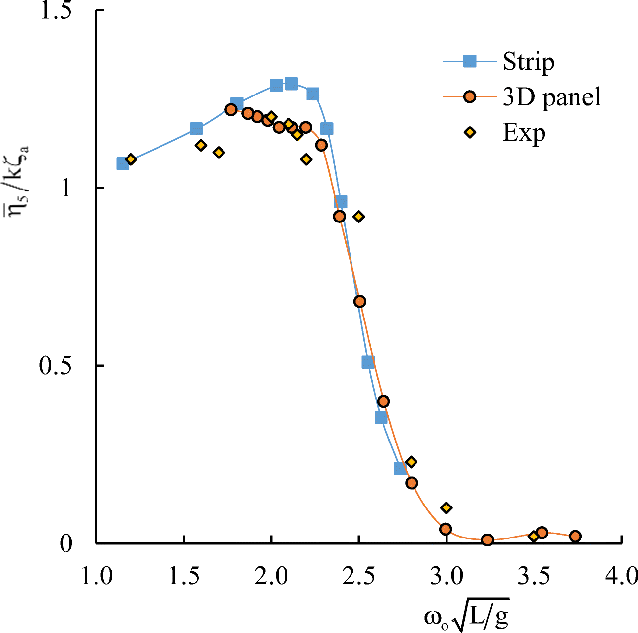
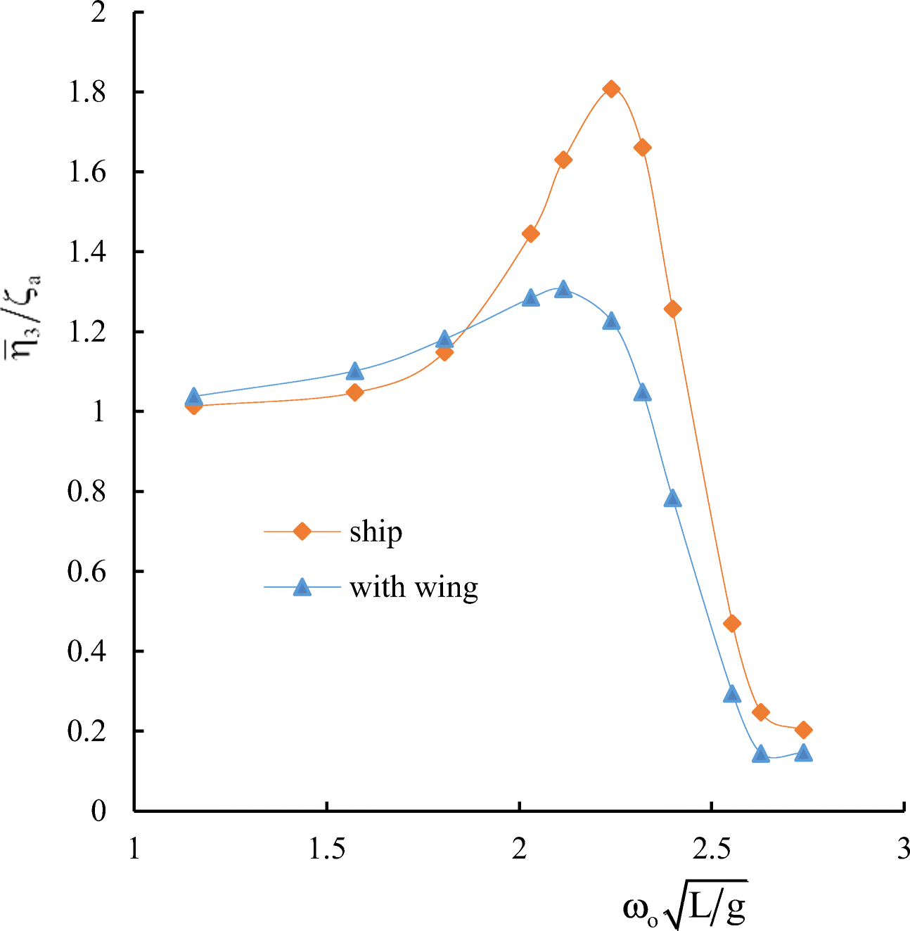
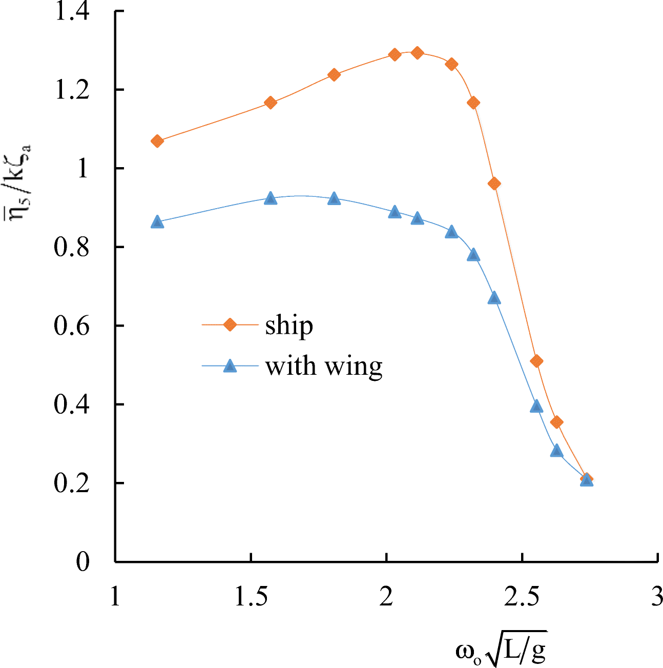
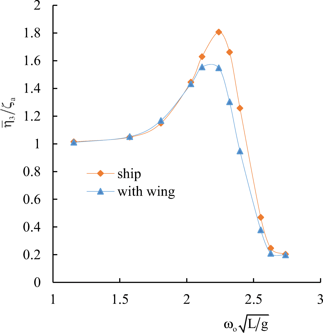
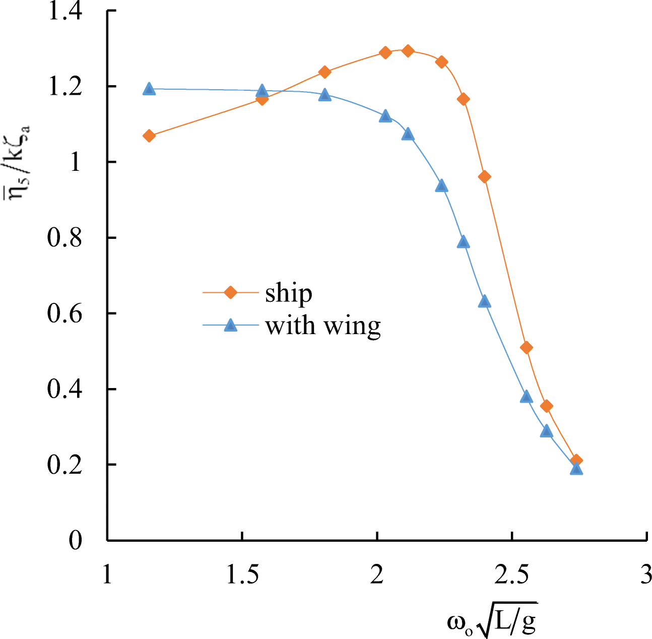
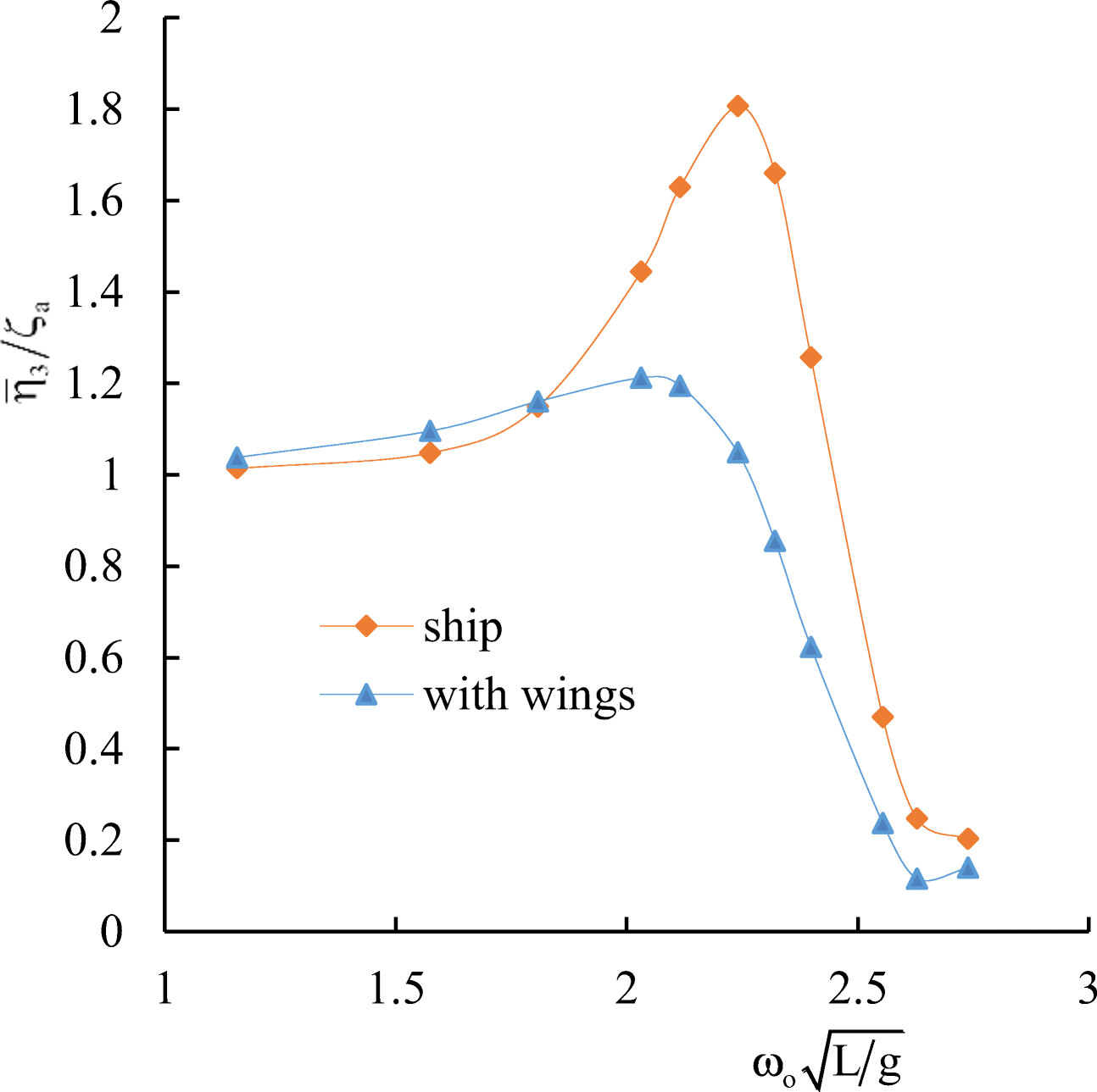
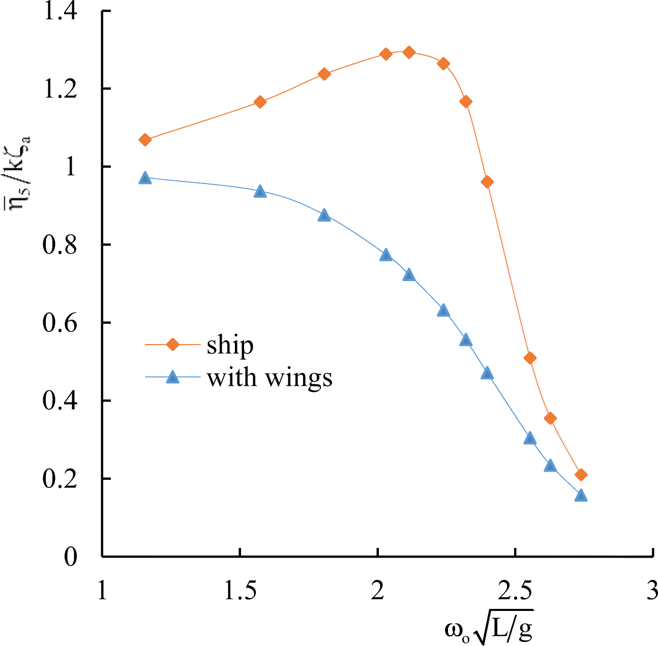
Table 1 General data of the container ship S-175Name S-175 Length, L (m) 175 Breadth, B (m) 25.4 Draught, T (m) 9.5 Depth, H (m) 15.4 Displacement (m) 24742 Block coefficient, δ 0.559 Midship section coefficient, β 0.974 Deadweight, DWT (t) 14827 Main engine, MAN B & W G60ME-C9 Specific fuel consumption, SFC (g/kWh) 167 Table 2 Wing characteristicsWing $\mathcal{N}\underline{\text{o}}$ 1 Wing $\mathcal{N}\underline{\text{o}}$ 2 Wing $\mathcal{N}\underline{\text{o}}$ 3 Wing type NACA 0012 Chord (m) 5 5 5 Span (m) 15 20 25 Aspect ratio, Λ 3 4 5 To study the motion of the ship with energy-saving wing devices numerically on a regular wave of the length λ, the following wavelength range was selected $ ^\lambda {/_L} $ (from 0.4 to 2.5). Calculations of heave and pitch motions of ship were carried out at Froude number Fr= 0.275 and heading angleβ = 180·. In the plots representing ship motions calculations, $ {\overline{\eta}}_3/{\zeta}_a $ indicates the dimensionless amplitude of heave, and $ {\overline{\eta}}_5/k{\zeta}_a $ the dimensionless amplitude of pitch.
The results of numerical simulation for the container ship S-175 without wings are presented in Figures 10 and 11 in comparison with the 3D panel method (Liu and Papanikolaou 2011) and experimental data of ITTC (1978). In Figures 10–17, $ {\omega}_o=\sqrt{gk} $ is the wave frequency; k is the wave number.
Comparative calculated data for S-175 without and with wings are shown in Figures 12–17.
It follows from comparative calculated data for heave and pitch motions of a container ship with and without wing devices (as shown in Figures 10–17) that additional wing devices contribute to decreasing heave and pitch motions. This fact has been repeatedly noted in the literature (Naito 2005; Terao and Isshiki 1991; Bøckmann 2015; Zin and Rozhdestvensky 2019a).
4 Determination of Time-Averaged Thrust on the Wing System
The theory of the flapping wing is used in this paper to determine the inertia and damping effects of the wings on the swaying ship and to determine the thrust generated by the oscillating wings. Used therewith are the formulas for calculating the derivatives of hydrodynamic coefficients and the time-averaged thrust force for the combination of heave-pitch oscillations of infinite-aspect-ratio wings.
The instantaneous thrust coefficient can be written as (Rozhdestvensky and Ryzhov 1985; Rozhdestvensky and Ryzhov 2003)
$$ {C}_t={C}_q+{C}_x $$ (10) where Cq− suction force coefficient and Cx− coefficient of the horizontal projection of the resulting normal loads.
For the given law of oscillations of the rigid wing, determined by the values of dimensionless amplitudes $ {\overline{\eta}}_3,{\overline{\eta}}_5,\overline{W} $ and phase $ {\varphi}_{\eta_3},{\varphi}_{\eta_5} $, the average thrust coefficient 〈Ct〉 over the period of oscillations $ T=\frac{2\pi }{k_a} $ can be calculated as follows:
$$ \begin{aligned} \left\langle {{C_t}} \right\rangle &= \mathop {\mathop \smallint \limits^T }\limits_0 \left( {{C_q} + {C_x}} \right){\rm{d}}t\\ & = \mathop {\mathop \smallint \limits^T }\limits_0 \left[ {\begin{array}{*{20}{l}} {\left\{ {\frac{\pi }{2}{{\left( {{a^{{{\dot \eta }_3}}}{{\dot \eta }_3} + {a^{{{\ddot \eta }_3}}}{{\ddot \eta }_3} + {a^{{\eta _5}}}{\eta _5} + {a^{{{\dot \eta }_5}}}{{\dot \eta }_5} + {a^W}W + {a^{\dot W}}\dot W} \right)}^2}} \right\} - }\\ {\left\{ {{\eta _5}\left( {C_z^{{{\dot \eta }_3}}{{\dot \eta }_3} + C_z^{{{\ddot \eta }_3}}{{\ddot \eta }_3} + C_z^{{\eta _5}}{\eta _5} + C_z^{{{\dot \eta }_5}}{{\dot \eta }_5} + C_z^WW + C_z^{\dot W}\dot W} \right)} \right\}} \end{array}} \right]{\rm{d}}t \end{aligned} $$ (11) where
$$ {\displaystyle \begin{array}{ll}{\dot{\eta}}_3=-{k}_a{\overline{\eta}}_3\sin \left({k}_at-{\varphi}_{\eta_3}\right);& {\ddot{\eta}}_3=-{k}_a^2{\overline{\eta}}_3\cos \left({k}_at-{\varphi}_{\eta_3}\right)\\ {}{\eta}_5={\overline{\eta}}_5\cos \left({k}_at-{\varphi}_{\eta_5}\right);& {\dot{\eta}}_5=-{k}_a{\dot{\eta}}_5\sin \left({k}_at-{\varphi}_{\eta_5}\right);\\ {}W=\overline{W}\cos \left({k}_at-{kx}_f\right);& \dot{W}=-{k}_a\overline{W}\sin \left({k}_at-{kx}_f\right)\end{array}} $$ Conducting the integration in the equation (11), we obtain the following expression for the time-averaged thrust coefficient:
$$ \begin{aligned} \left\langle {{C_t}} \right\rangle =& \frac{{\pi \bar \eta _3^2k_a^2}}{4}\left[ {{{\left( {{a^{{{\dot \eta }_3}}}} \right)}^2} + k_a^2{{\left( {{a^{{{\ddot \eta }_3}}}} \right)}^2}} \right] + \frac{{\pi \bar \eta _5^2}}{4}\left[ {{{\left( {{a^{{\eta _5}}}} \right)}^2} + k_a^2{{\left( {{a^{{{\dot \eta }_5}}}} \right)}^2}} \right] \\ &+ \frac{{\pi {{\bar W}^2}}}{4}\left[ {{{\left( {{a^W}} \right)}^2} + k_a^2{{\left( {{a^{\dot W}}} \right)}^2}} \right] - \frac{{{{\bar \eta }_5}{{\bar \eta }_3}}}{2}\left[ {\begin{array}{*{20}{l}} {{k_a}\sin \left( {{\varphi _{{\eta _5}}} - {\varphi _{{\eta _3}}}} \right) \cdot }\\ {\left\{ {\begin{array}{*{20}{c}} {\pi \left( {{a^{{{\dot \eta }_3}}}{a^{{\eta _5}}} + k_a^2{a^{{{\ddot \eta }_3}}}{a^{{{\dot \eta }_5}}}} \right)}\\ { - C_z^{{{\dot \eta }_3}}} \end{array}} \right\}} \end{array}} \right] \\ &+ \frac{{{{\bar \eta }_5}{{\bar \eta }_3}}}{2}\left[ {k_a^2\cos \left( {{\varphi _{{\eta _5}}} - {\varphi _{{\eta _3}}}} \right) \cdot \left\{ {\pi \left( {{a^{{{\dot \eta }_3}}}{a_{{{\dot \eta }_5}}} + {a^{{{\ddot \eta }_3}}}{a^{{\eta _5}}}} \right) + C_z^{{{\ddot \eta }_3}}} \right\}} \right]\\ & - \frac{{\bar \eta _5^2}}{2}C_z^{{\eta _5}} - \frac{{{k_a}}}{2}{{\bar \eta }_3}\bar W\pi \sin \left( {k{x_f} - {\varphi _{{\eta _3}}}} \right) \cdot \left[ {{a^{{{\dot \eta }_3}}}{a^W} + k_a^2{a^{{{\ddot \eta }_3}}}{a^{\dot W}}} \right]\\ & + \frac{{k_a^2}}{2}{{\bar \eta }_3}\bar W\pi \cos \left( {k{x_f} - {\varphi _{{\eta _3}}}} \right) \cdot \left[ {{a^{{{\dot \eta }_3}}}{a^{\dot W}} - {a^{{{\ddot \eta }_3}}}{a^W}} \right]\\ & + \frac{{{{\bar \eta }_5}\bar W}}{2}\left[ {{k_a}\sin \left( {k{x_f} - {\varphi _{{\eta _5}}}} \right) \cdot \left\{ {\pi \left( {{a^{{\eta _5}}}{a^{\dot W}} - {a^{{{\dot \eta }_5}}}{a^W}} \right) - C_z^{\dot W}} \right\}} \right]\\ & + \frac{{{{\bar \eta }_5}\bar W}}{2}\left[ {\cos \left( {k{x_f} - {\varphi _{{\eta _5}}}} \right) \cdot \left\{ {\pi \left( {{a^{{\eta _5}}}{a^W} + k_a^2{a^{{{\dot \eta }_5}}}{a^{\dot W}}} \right) - C_z^W} \right\}} \right] \end{aligned} $$ (12) To determine time averaged thrust force, we need to multiply the averaged thrust coefficient by the dynamic head and the wing reference area, i.e.,
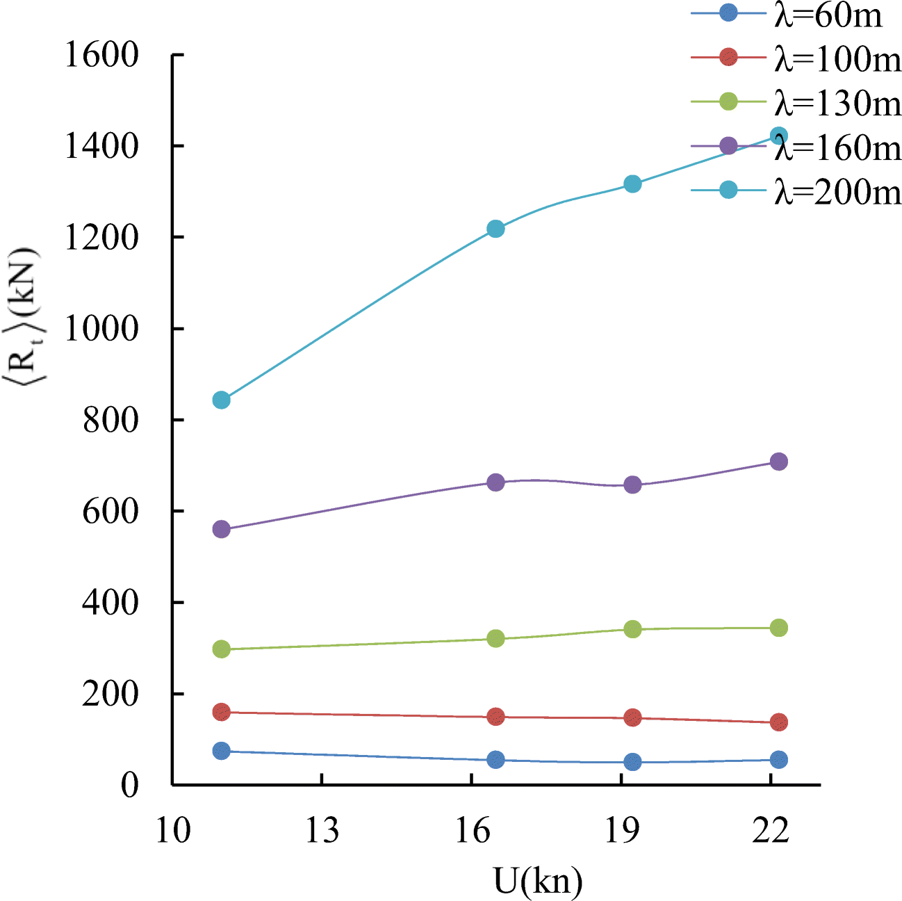
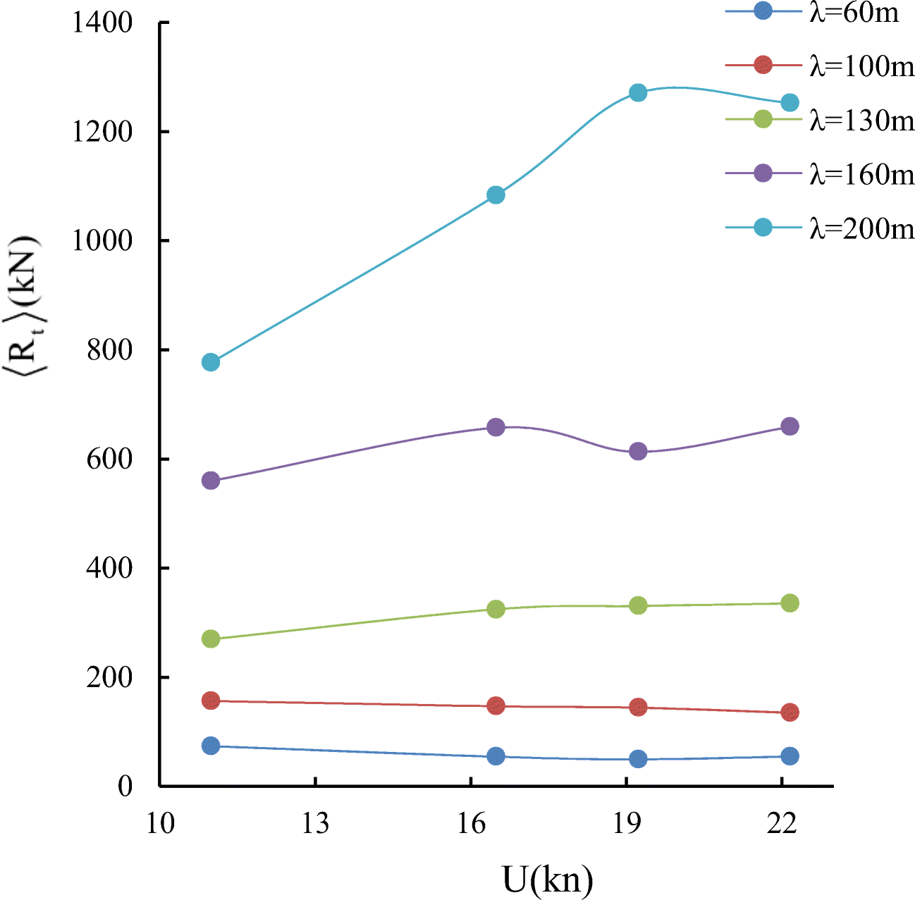
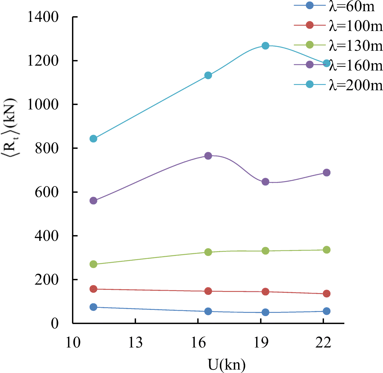
$$ \left\langle {R}_t\right\rangle =\left\langle {C}_t\right\rangle \frac{\rho {U}^2}{2}{S}_{r,\mathrm{wing}} $$ (13) Calculated averaged thrust force curves for different wavelengths and arrangement of the wings are shown in Figures 18–20.
Considering Figures 18-20, we can note that the thrust generated by two wings can be larger, comparable or even lower than that generated by one wing. As a matter of fact, the total thrust of two-wing system depends on multiple factors such as the ratio of the distance between wings to the wavelength, variation of the wetted section areas length-wise, and so on.
5 The Total Drag of a Ship with Wings
In order to evaluate the thrust and power savings due to energy harvesting wings, it is convenient to calculate total drag of the ship-plus-wings system.
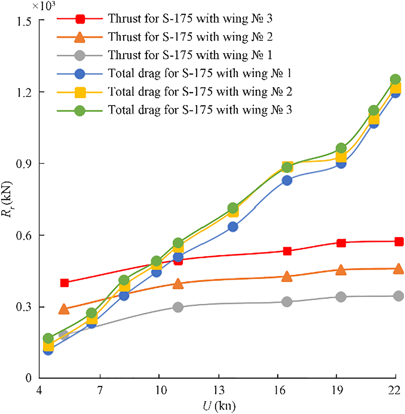
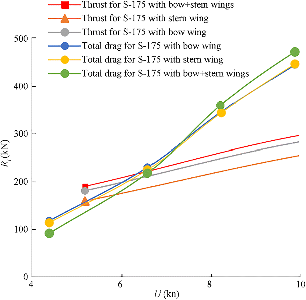
Further in this paper for the case when the ship is propelled exclusively by wave power, we would suggest that the resulting speed of ship translational motion is reached when the wave-generated time averaged thrust would equal the total drag of the ship. The total drag of the ship can be represented as the sum of its components due to viscosity, wings' induced drag, and the wave resistance. The latter can be written as a sum of the wave resistance in calm water and added wave resistance.
5.1 Holtrop Part of the Total Drag
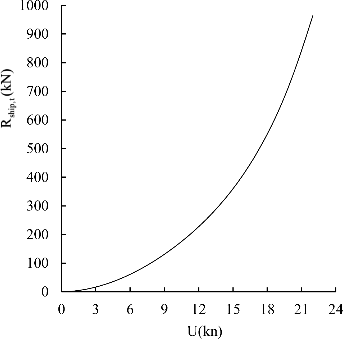
Holtrop and Mennen (1982) method is arguably the most popular method to estimate resistance and powering of displacement type ships. To calculate the resistance using the Holtrop method, one uses the following formula:
$$ {R}_{\mathrm{ship},t}={R}_f\left(1+{k}_{fd}\right)+{R}_{AP}+{R}_W+{R}_B+{R}_{TR}+{R}_A $$ (14) where Rf− frictional resistance; RAP− resistance of appendages; RW− wave-making resistance; RB− additional pressure resistance of bulbous bow; RTR−additional pressure resistance of immersed transom stern; RA− model-ship correlation resistance; and kfd –viscous form drag coefficient. Note that the components of the resistance RAP and RTR were not taken into account during the calculation. Note that formula (14), describing the Holtrop part of the total drag does not include added wave resistance. The latter will be discussed in the following paragraph (Figure 21).
5.2 Added Wave Resistance Beukelman-Gerritsma Formula
When the ship is moving in waves, its drag can increase by 15%–30%. The estimation of added resistance in waves is one of the important tasks of ship design in terms of engine selection, fuel consumption, and route time estimation Alexandersson (2009).
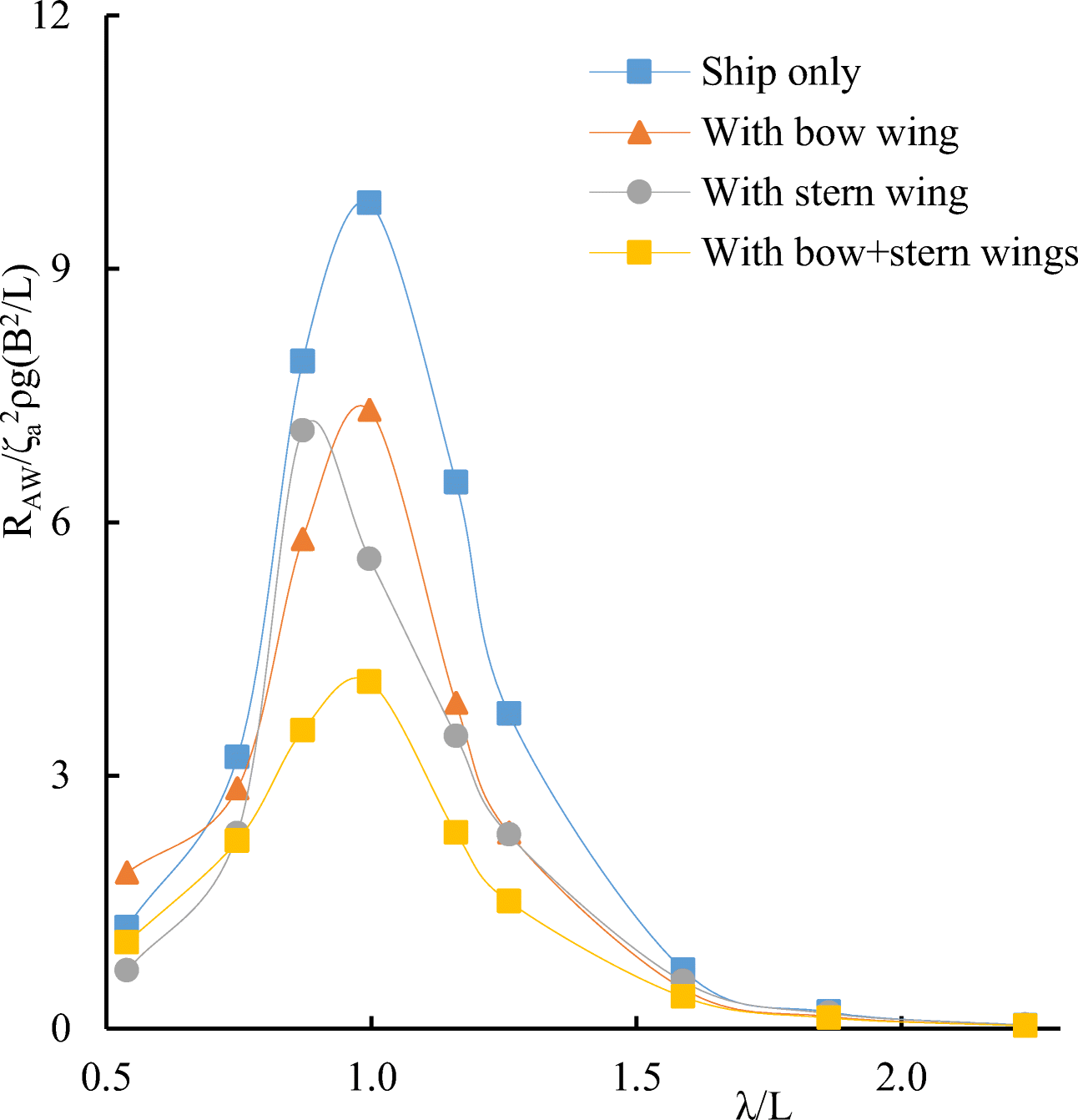
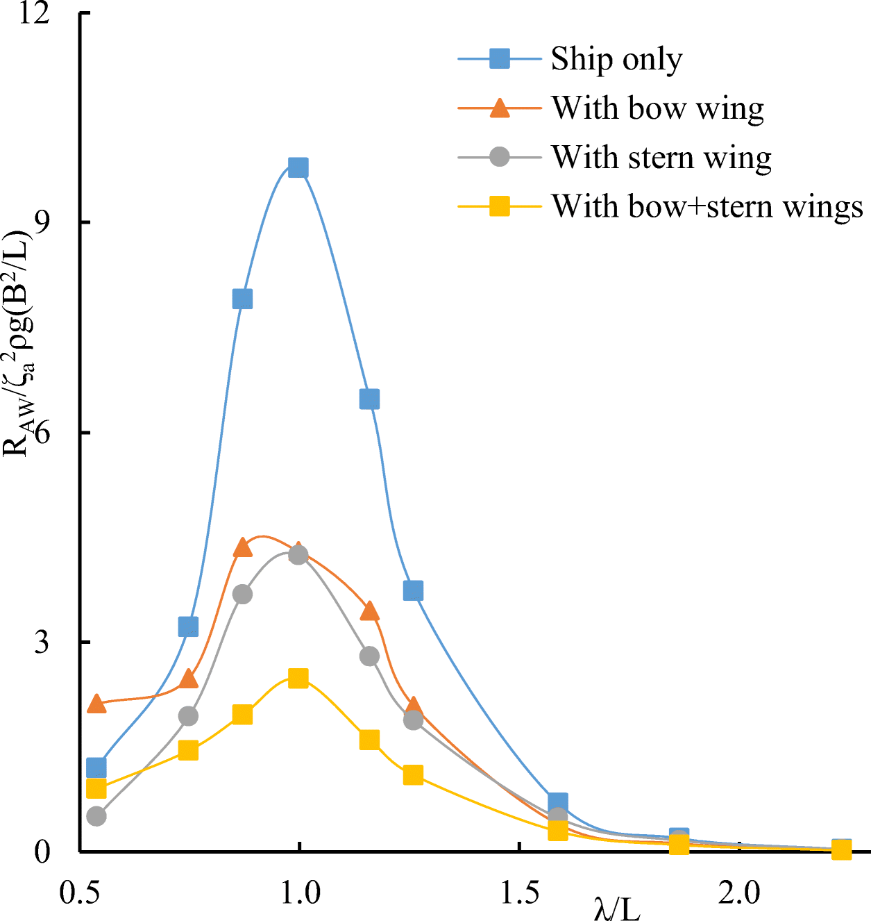
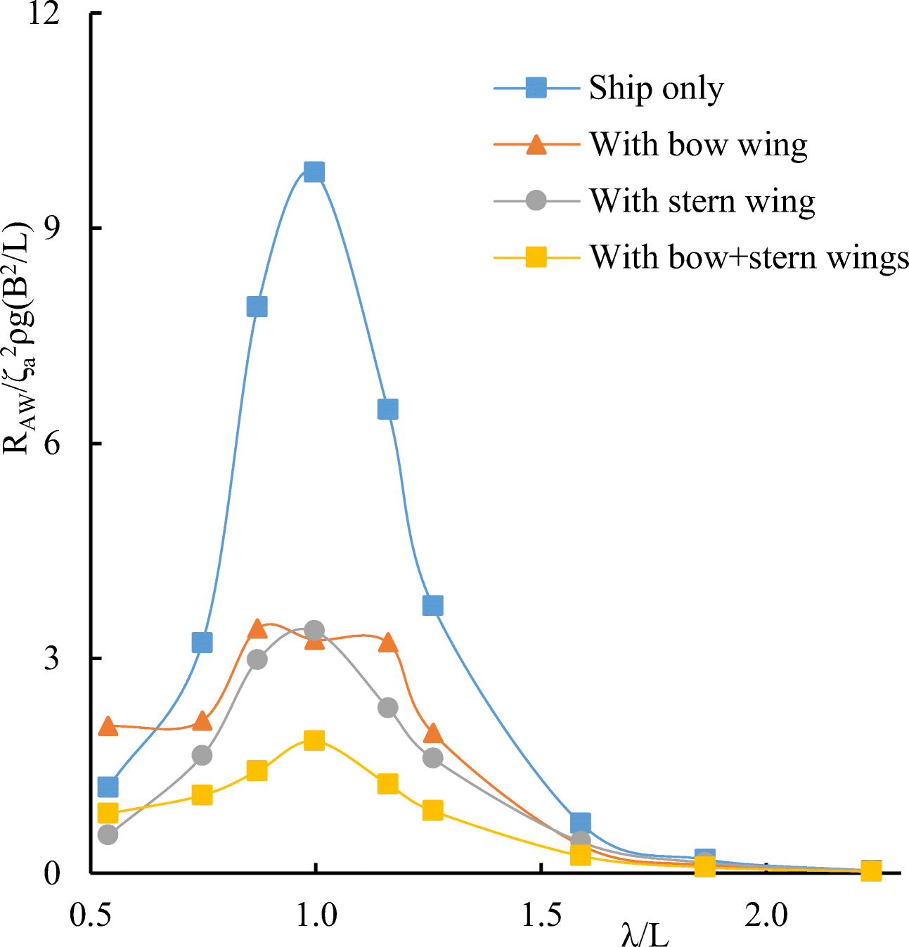
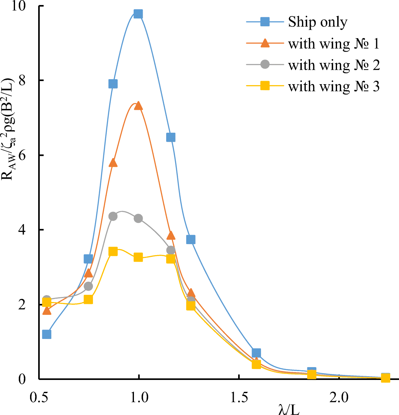
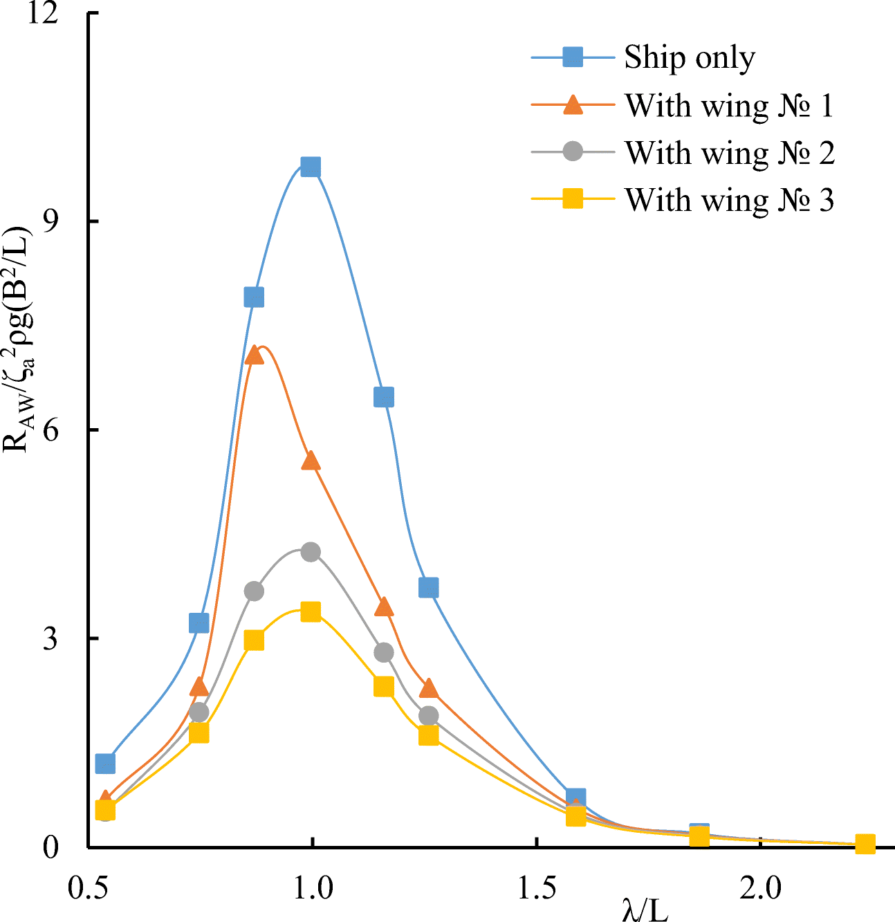
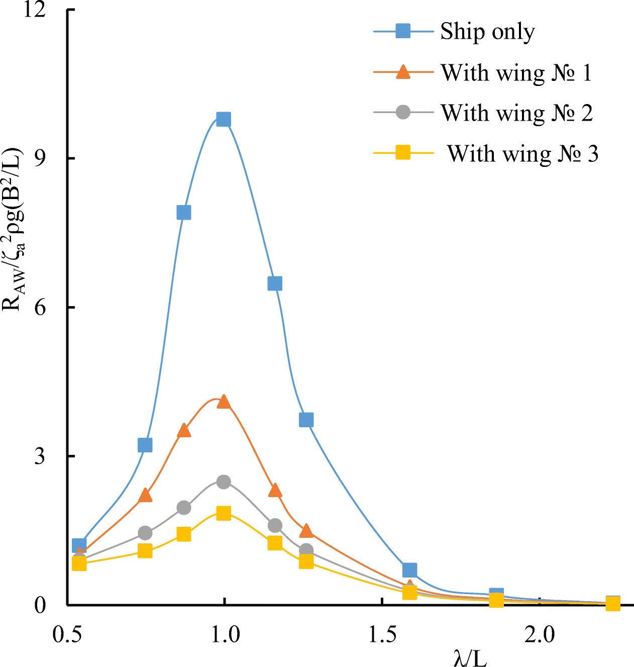
The added resistance of ships has been studied by various methods (Wenyang and Chuanqing 2013; Liang et al. 2016; Liu et al. 2011). As far as the authors know, the use of wing devices to reduce heave and pitch motions and added resistance of ships was first proposed by John Spencer Avis (1989). He found a way to reduce the heave and pitch motions and added resistance of the yacht using the bow wing and tested this effect in practice on a regular head sea. And then many researchers have studied the reduction of added resistance of the ship using wing devices (Naito 2005; Zin Min 2020a, 2020b; Rozhdestvensky 2019b & Rozhdestvensky and Htet 2020; Zin Min 2020a, 2020b; Naito et al. 2001).
Table 3 Speed, thrust, and wavelength in the calculated case for wings of different sizes and different placesλ (m) U (kn) Rt (kN) Type of wing 130 5.4 162 Stern wing $\mathcal{N}\underline{\text{o}}$ 1 130 6.2 180 Bow wing $\mathcal{N}\underline{\text{o}}$ 1 130 6.9 225 Bow+stern wings $\mathcal{N}\underline{\text{o}}$ 1 130 7.8 310 Bow wing $\mathcal{N}\underline{\text{o}}$ 2 130 9.6 465 Bow wing $\mathcal{N}\underline{\text{o}}$ 3 The radiated energy method for added wave resistance due to ship motions was originally applied by Gerritsma and Beukelman (1972), based on the energy conservation principle. The method consists in determining the energy of the waves created by the ship when performing heaving and pitching motions, and since the main role in wave formation is played by vertical damping, it takes into account only heave and pitch motions.
$$ E=\underset{0}{\overset{T}{\int }}\underset{0}{\overset{L}{\int }}{b}^{\prime }.{U}_z\mathrm{d}x\mathrm{d}t $$ (15) where $ {U}_z=-U{\dot{\eta}}_5-{\dot{\eta}}_3+{x}_f{\dot{\eta}}_5+i\left[{\omega \zeta}_a{e}^{kZ}{e}^{i\Big({\omega}_et-{kx}_f\cos \left(\beta \right)}\right] $ and b′ = b33 − U(da33/dxf); b33 and a33 are called the damping coefficient and the added mass, U− ship speed, and Uz− amplitude of the relative velocity. The energy radiated during a single oscillation period can also be expressed in terms of added resistance. Then equation (15) takes the form
$$ E={R}_{aw}{\lambda}_{\beta }={R}_{aw}\left(\frac{\lambda }{\cos \beta}\right)={R}_{aw}\left(\frac{2\pi}{-k\cos \beta}\right) $$ (16) where λβ− distance covered by the ship when it moves at an angle to the wave front.
For dimensionless added resistance, taking into account the heave and pitch motions, we can obtain
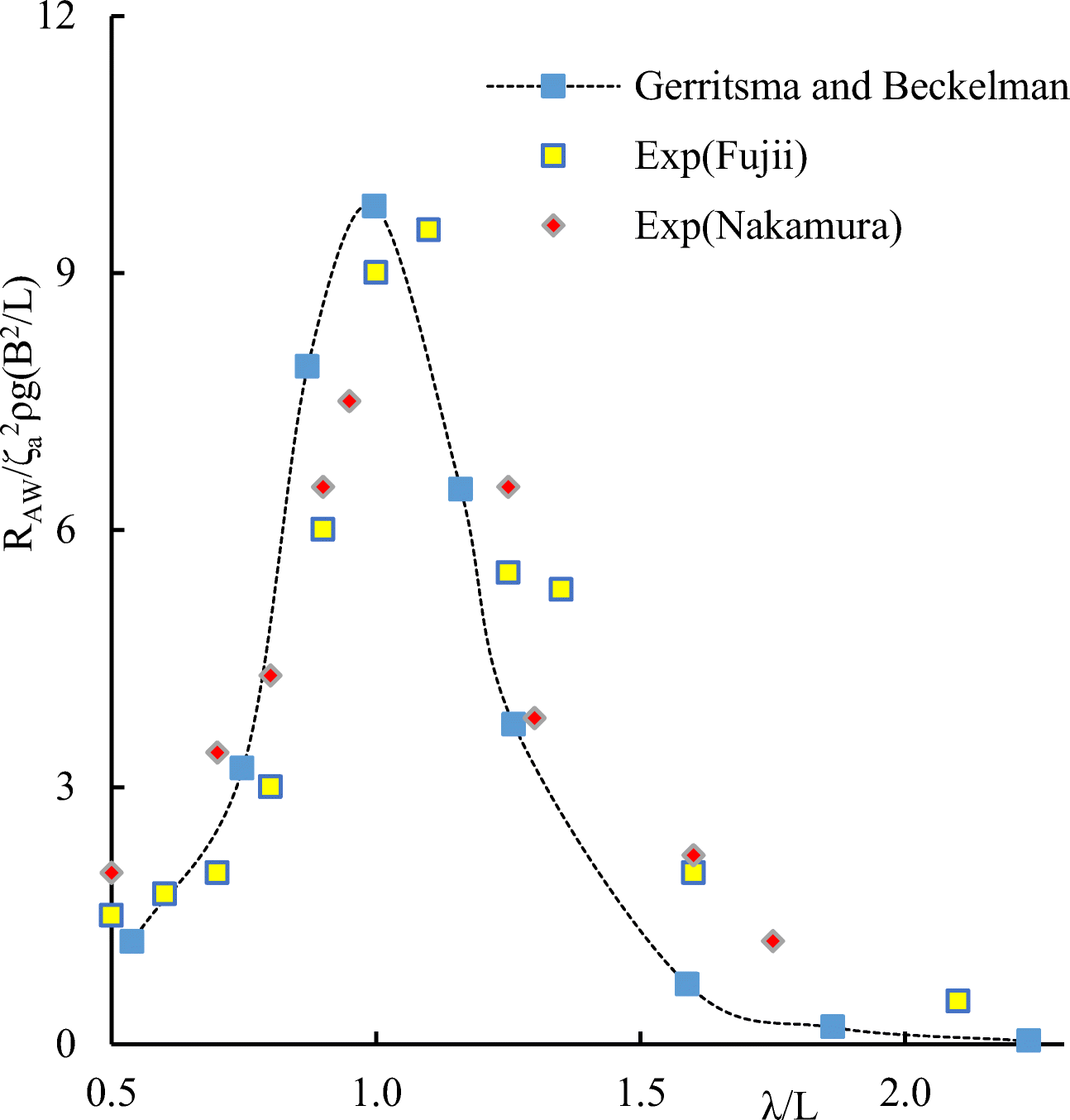
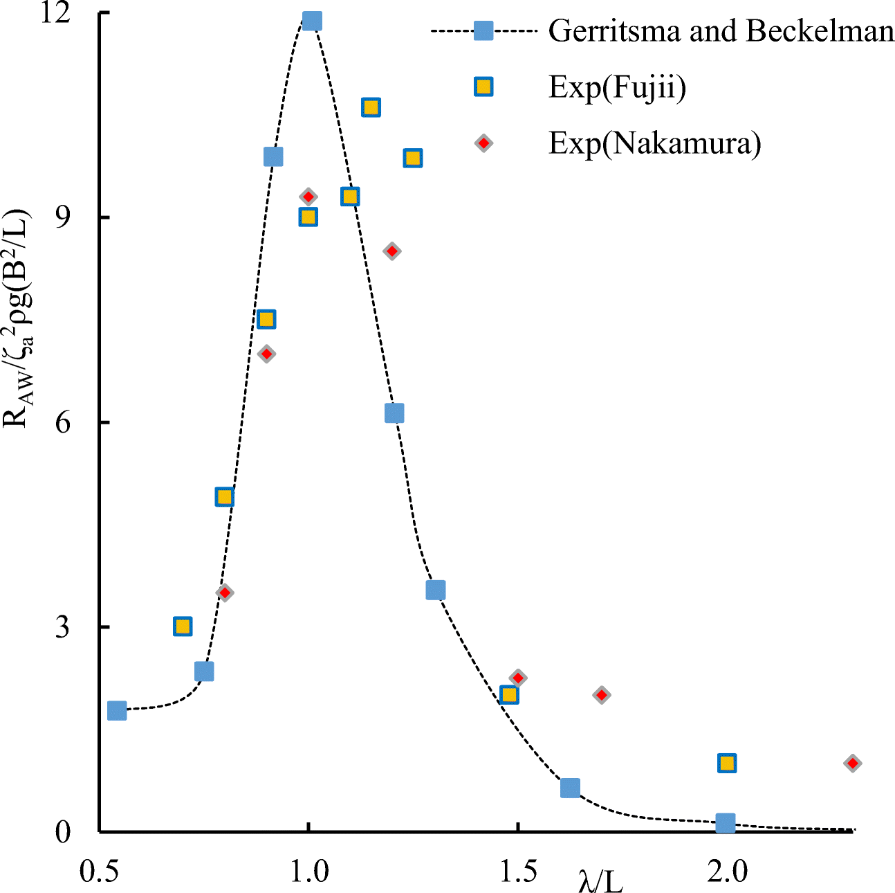
$$ {R}_{aw}=\frac{R_{AW}}{\rho g{\zeta}_a^2\left({B}^2/L\right)}=\frac{-k\cos \beta }{2\pi}{\int}_0^T\underset{0}{\overset{L}{\int }}{b}^{\prime }{U}_z^2{\mathrm{d}x}_f\mathrm{dt} $$ (17) Results of numerical calculations of added wave resistance for container ship S-175 were compared with experimental data of Fujii and Takahashi (1975) and experimental data of Nakamura (1976).
Calculations of the added resistance of the ship were carried out at the Froude numbers Fr = 0.2 and Fr = 0.25, heading angle β = 180· (in head seas). The added wave resistance values for the ship found by numerical simulation are in satisfactory agreement with experimental data. The following notation is used in the graphs shown in Figures 22–29: $ {R}_{AW}/\rho g{\varsigma}_a^2\left({B}^2/L\right) $ dimensionless added resistance of the ship (ship with wing devices).
5.3 Evaluation of Speed of a Ship Propelled Entirely by Wave Power
Neglecting drag of the wings as compared with that of the ship we can determine the total drag RD as
$$ {R}_D={R}_{\mathrm{ship},t}+{R}_{\mathrm{ship}+\mathrm{wing}, AW}+{R}_{\mathrm{wing}} $$ (18) where Rship, t− corresponds to Holtrop part of the ship drag and Rship + wing, AW− added resistance of the ship with wings, Rwing− viscous drag of the wing.
The viscous drag of the wing founded by the following expansion
$$ {R}_{\mathrm{wing}}=\frac{\rho {U}^2}{2}{C}_f{S}_{\mathrm{wing}} $$ (19) where Swing− wetted surface area of wing.
The friction coefficient is determined by the formulas for turbulent according to the Prandtl-Schlichting formula
$$ {C}_f=\frac{0.455}{{\left(\log \operatorname{Re}\right)}^{2.58}} $$ (20) where $ {R}_e=\frac{Uc}{\nu } $ is Reynolds number.
6 Estimation of the EEDI for a Ship with Energy-Saving Devices
The EEDI for new ships has become an important technical measure aimed at promoting the use of more energy-efficient equipment and engines. EEDI requires a minimum level of energy efficiency per mile of transportation capacity (for example, ton-mile) for various types and sizes of vessels. This index combines important aspects of ship design, ship theory, economics, and ecology.
In 2011, the International Maritime Organization (International Maritime Organization 2011) made this index mandatory for new ships as a measure to reduce the carbon emissions from ships.
For large vessels, such as tankers over 20, 000 tons and container ships over 15, 000 tons, EEDI is required to determine the amount of CO2 generated during their operation. It applies to ships built after January 1, 2013, and will require a 10% increase in efficiency for ships built in 2015–2019, 20% in 2020–2024, and 30% from 2025. At present, several projects are underway to develop the EEDI calculation of the ship, for examples (Huilin Ren et al. 2019; Faitar and Novac 2016; Lindstad et al. 2019).
Since EEDI is a measure of ship CO2 emissions in calm water that is rarely found in the ocean, International Maritime Organization (2014a) has also defined it for representative sea conditions as EEDIweather, formed by dividing EEDI by the rate of loss of speed due to wind and wave action. The representative sea state to be used in the EEDIweather calculation includes head wind and wave parameters (International Maritime Organization 2012).
This paper presents EEDI and EEDIweather estimates of CO2 emissions based on IMO requirements. The EEDIweather calculation has been made for a ship without and with wing devices; the latter intended for the wave energy-aided ship propulsion.
6.1 The EEDI for a Container Ship
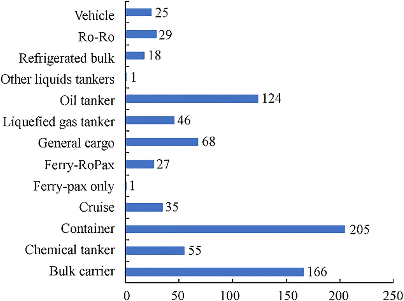
Figure 32 shows CO2 emissions by ship type in 2012 (International Maritime Organization 2014, 2014a), among which the maximum was observed from a container ship. In this paper, as an example, we consider a container ship, the characteristic data of which are shown in Table 1.
The goal of the EEDI concept introduced by IMO is to ensure that ships have engines and equipment that are the least polluting. Essentially, EEDI is a measure of the amount of CO2 emitted by a ship (ton-nm).
EEDI (g.CO2/t nm) can be determined by the following expression:
$$ \mathrm{EEDI}=\frac{P_{\mathrm{ME}}\cdot {SFC}_{\mathrm{ME}}\cdot {C}_{\mathrm{Fuel}}}{\mathrm{DWT}\cdot U} $$ (21) The required power to propel the ship by the main engine can be evaluated with use of the formula introduced in Danilovsky (2014) and Aung (2020)
$$ {P_{{\rm{ME}}}}{ = ^{\left( {\frac{{{R_D} \cdot 0.514U}}{{{\eta _s} \cdot {\eta _g} \cdot {\eta _p}}}{k_z} + {N_{PA}} - {N_{TP}}} \right)}}{/_{{Z_E}}} $$ (22) where PME—the power of the main engine in operational mode, kW; SFCME—specific fuel consumption of the main engine, g/kWh; DWT—the ship's deadweight, tons; and U—ship's speed in operational mode, knots. RD− the total resistance of the ship, ηs− shaft efficiency, ηg− gearbox efficiency, ηp− propulsive coefficient, kz− sea margin coefficient, NPA− power of assembled mechanisms, NTP− recovery turbine power, and ZE− the total engine number. Neglecting NPA, NTP contributions and assuming ZE = 1, finally, we reduce (22) to $ {P}_{\mathrm{ME}}=\frac{R_T\cdot 0.514U}{\eta_s\cdot {\eta}_g\cdot {\eta}_p} $, specify ηs = 0.98, ηg = 1, ηp = 0.65 and, in accordance with the International Maritime Organization (2014; 2018) reference take Cfuel = 3.114 [g CO2/t Fuel] for heavy fuel oil.
The attained EEDI is determined based on the reduction factor X for the ship. The latter depends on the year of construction of the ship (Table 4). The relationship between these parameters will determine the attained EEDI value using the formula (24):
$$ \mathrm{Attained}\ \mathrm{EEDI}=1-\left(\frac{X}{100}\right)\times \mathrm{Reference}\ \mathrm{line}\ \mathrm{value} $$ (23) Table 4 Reduction factors for the EEDI relative to the EEDI reference lineShip type Container ship Size 15000 DWT and above 10000–15000 DWT Phase 0 1 Jan 2013–31 Dec 2014 0 – Phase 1 1 Jan 2015–31 Dec 2019 10 0–10* Phase 2 1 Jan 2020–31 Dec 2024 20 0–20* Phase 3 1 Jan 2025 and onwards 30 0–30* *Reduction factor to be linearly interpolated between the two values dependent upon ship size. The lower value of the reduction factor is to be applied to the smaller ship size The EEDI reduction ratio (X) is the percentage of EEDI reduction relative to the base level of this index. The value of the "reduction factor" is determined by the International Maritime organization (IMO) (see Table 4).
6.2 Calculation of EEDIweather
EEDIweather is an EEDI achieved with a headwind of 6 on the Beaufort scale and a wave (International Maritime Organization 2014a; International Maritime Organization 2018). When a ship is operated in representative sea conditions, its resistance is higher than in calm water. According to the IMO guidelines, ship's resistance of EEDIweather are calculated as follows:
$$ {R}_D={R}_{\mathrm{ship},t}+{R}_{\mathrm{ship} AW, wind}+\Delta {R}_{\mathrm{ship} AW, wave} $$ (24) where Rship, t− the total resistance of a ship in a calm sea condition, RAW, wind− added resistance due to wind, and RAW, wave− added resistance due to waves. Note that in this paper, we neglect the magnitude RAW, wind as compared to ship-related terms in (24).
Our purpose here is to evaluate EEDIweather for the case of the ship with energy-saving wings. To provide comparative analysis, we need to know the power required to propel a ship with and without wings. First, let's find the total resistance that includes time-averaged thrust from the wing and equation (24) changes. Total resistance RD
$$ {R}_{D,\mathrm{nowing}}={R}_{\mathrm{ship},t}+{R}_{\mathrm{ship}, AW} $$ (25) $$ {R}_{D,\mathrm{withwing}}={R}_{\mathrm{ship},t}+{R}_{\mathrm{ship}+\mathrm{wing}, AW}+{R}_{\mathrm{wing}}-\left\langle {R}_t\right\rangle, $$ (26) where Rship, t is a Holtrop part of the drag, Rship + wing, AW− added wave resistance of the ship with wings devices, Rwing viscous drag of the wing, 〈Rt〉− time-averaged thrust force.
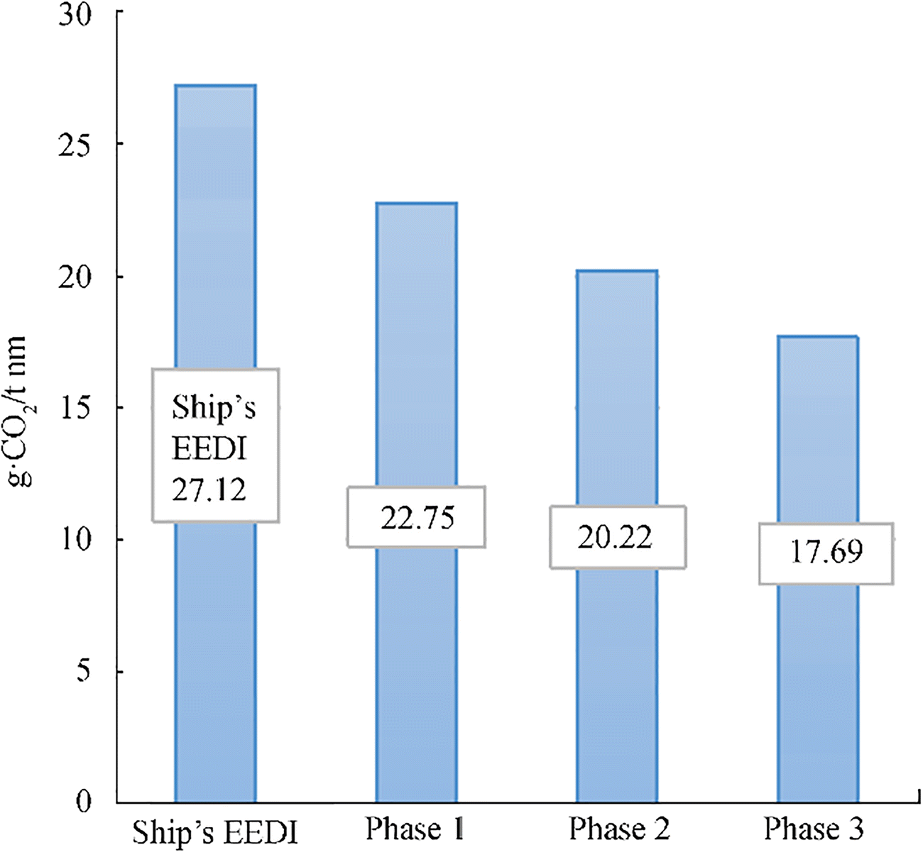
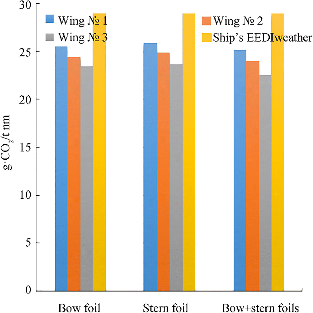
In reference (Bøckmann and Steen 2016), the additional resistance of the ship is determined according to the rules of International Maritime Organization 2012 and with account of the theory of Gerritsma and Beukelman which furnishes results close to the IMO guidelines requirements. To estimate the EEDI and EEDIweather for a container ship, exemplified in this paper, we determine the power required to move at a given speed for a ship without and with wing through the use of Danilovsky (2014) formula. Note that the calculation of the EEDI (g • CO2/t nm) is important to estimate ship engine CO2 emissions (g/t nm) and to assess ship's energy efficiency at sea. The EEDI, EEDIweather, and required EEDI depend on the year of construction of the container ship and are calculated with account of certain detained parameters as per Table 5 (Figure 33) and Table 6 (Figure 34). When estimating EEDIweather, the total drag and required power are calculated not only for a single ship but also for a ship with wings, driven in whole or partially through the use of the wave energy.
Table 5 Results EEDI and attained EEDIEEDI of ship (g.СО2/t nm) Phase 1 1 Jan 2015–31 Dec 2019 Phase 2 1 Jan 2020–31 Dec 2024 Phase 3 1 Jan 2025 and onwards Uw(kn) 27.31 22.75 20.22 17.69 22 Table 6 Results EEDIweather of a ship with wing devicesEEDIweather (g.СО2/t nm) Locations and types of wings Bow $\mathcal{N}\underline{\text{o}}$ 1 Bow $\mathcal{N}\underline{\text{o}}$ 2 Bow $\mathcal{N}\underline{\text{o}}$ 3 Stern. $\mathcal{N}\underline{\text{o}}$ 1 Stern $\mathcal{N}\underline{\text{o}}$ 2 Stern $\mathcal{N}\underline{\text{o}}$ 3 Bow+stern wings $\mathcal{N}\underline{\text{o}}$ 1 Bow+stern wing $\mathcal{N}\underline{\text{o}}$ 2 Bow+stern wing $\mathcal{N}\underline{\text{o}}$ 3 28.99 25.86 24.49 23.47 26.01 24.9 23.72 25.187 24.05 22.639 7 Conclusions
1) Proposed in this paper is a mathematical model of the ship with wing devices that uses renewable energy of the ocean, enabling better understanding of the mechanism and efficiency of the implementation of energy-saving wing devices that convert wave energy into thrust forces.
2) The model facilitates estimating seaworthiness of a ship with wing devices during the design process and helps to explore options for directional influence on the ship's heave and pitch motions to moderate those and, correspondingly, reduce added wave resistance.
3) It has been found that the ship with wing devices has reduced heave and pitch motions and added wave resistance.
4) It has been shown how the efficiency of energy-saving wing devices and associating reduction for heave and pitch motions and added resistance depends on the configuration and parameters of the system (bow wing, stern wing, bow plus stern wings)
5) In particular, it has been found that in head seas the bow wing is more efficient in moderating heave and pitch motions than the stern one.
6) The wing area increase results in increase of the thrust, but at the same time the wing drag increases, which must be taken into account when designing.
7) Evaluating indices EEDI, EEDIweather allows to estimate the level of CO2 emissions and compare these data with the requirements of the IMO.
8) EEDIweather for a ship with wings is always lower than for a ship without wings reflecting a reduction in CO2 emissions occurring as a result of fuel consumption at representative sea conditions. This may enable ship designers and owners to ensure lower fuel costs and protect the environment.
9) Future work will be focused on further verification, experimental validation of the mathematical model discussed herein, and extension of the present models to the case of a ship operating in different sea conditions (e. g., quartering and following seas) and irregular waves. Improvement is envisaged of the description of the hydrodynamics of energy-saving wings through the application of unsteady lifting line theory.
-
Figure 1 An artist's view of Russian research fishing vessel 174 tons (Nikolaev et al. 1995)
Figure 2 Research model of the Norwegian University of Science and Technology (Bøckmann 2015)
Figure 3 Full-scale experience with retractable bow foils on M/F TEISTIN (Wavefoil 2019)
Figure 4 EU-funded project. Combination of ship engine and bow wing propulsion innovation systems (Wärtsilä 2020)
Figure 5 USV AutoNaut of the University of Southampton (Bowker et al. 2016)
Table 1 General data of the container ship S-175
Name S-175 Length, L (m) 175 Breadth, B (m) 25.4 Draught, T (m) 9.5 Depth, H (m) 15.4 Displacement (m) 24742 Block coefficient, δ 0.559 Midship section coefficient, β 0.974 Deadweight, DWT (t) 14827 Main engine, MAN B & W G60ME-C9 Specific fuel consumption, SFC (g/kWh) 167 Table 2 Wing characteristics
Wing $\mathcal{N}\underline{\text{o}}$ 1 Wing $\mathcal{N}\underline{\text{o}}$ 2 Wing $\mathcal{N}\underline{\text{o}}$ 3 Wing type NACA 0012 Chord (m) 5 5 5 Span (m) 15 20 25 Aspect ratio, Λ 3 4 5 Table 3 Speed, thrust, and wavelength in the calculated case for wings of different sizes and different places
λ (m) U (kn) Rt (kN) Type of wing 130 5.4 162 Stern wing $\mathcal{N}\underline{\text{o}}$ 1 130 6.2 180 Bow wing $\mathcal{N}\underline{\text{o}}$ 1 130 6.9 225 Bow+stern wings $\mathcal{N}\underline{\text{o}}$ 1 130 7.8 310 Bow wing $\mathcal{N}\underline{\text{o}}$ 2 130 9.6 465 Bow wing $\mathcal{N}\underline{\text{o}}$ 3 Table 4 Reduction factors for the EEDI relative to the EEDI reference line
Ship type Container ship Size 15000 DWT and above 10000–15000 DWT Phase 0 1 Jan 2013–31 Dec 2014 0 – Phase 1 1 Jan 2015–31 Dec 2019 10 0–10* Phase 2 1 Jan 2020–31 Dec 2024 20 0–20* Phase 3 1 Jan 2025 and onwards 30 0–30* *Reduction factor to be linearly interpolated between the two values dependent upon ship size. The lower value of the reduction factor is to be applied to the smaller ship size Table 5 Results EEDI and attained EEDI
EEDI of ship (g.СО2/t nm) Phase 1 1 Jan 2015–31 Dec 2019 Phase 2 1 Jan 2020–31 Dec 2024 Phase 3 1 Jan 2025 and onwards Uw(kn) 27.31 22.75 20.22 17.69 22 Table 6 Results EEDIweather of a ship with wing devices
EEDIweather (g.СО2/t nm) Locations and types of wings Bow $\mathcal{N}\underline{\text{o}}$ 1 Bow $\mathcal{N}\underline{\text{o}}$ 2 Bow $\mathcal{N}\underline{\text{o}}$ 3 Stern. $\mathcal{N}\underline{\text{o}}$ 1 Stern $\mathcal{N}\underline{\text{o}}$ 2 Stern $\mathcal{N}\underline{\text{o}}$ 3 Bow+stern wings $\mathcal{N}\underline{\text{o}}$ 1 Bow+stern wing $\mathcal{N}\underline{\text{o}}$ 2 Bow+stern wing $\mathcal{N}\underline{\text{o}}$ 3 28.99 25.86 24.49 23.47 26.01 24.9 23.72 25.187 24.05 22.639 -
Alexandersson M (2009) A study of methods to predict added resistance in waves. Master thesis. KTH Center of Naval Architecture, Stockholm, pp 1–65 Angvik I (2009) Application of an active foil propeller on an offshore vessel. M. Sc. thesis. Norwegian University of Science and Technology, Norway Aung HP (2020) Computer-aided design and optimization of propulsion systems with medium-speed engines: Ph. D thesis. –Saint-Petersburg, SMTU (in Russian) Avis JS (1989) Reducing added resistance using an anti-pitching foil. University of British Columbia. Master of Applied Science, Vancouver, Canada Belibassakis KA, Filippas E (2015) Ship propulsion in waves by actively controlled flapping foils. Appl Ocean Res 52: 1–11. https://doi.org/10.1016/j.apor.2015.04.009 Belibassakis KA, Politis GK (2013) Hydrodynamic performance of flapping wings for augmenting ship propulsion in waves. Ocean Eng 72: 227–240. https://doi.org/10.1016/j.oceaneng.2013.06.028 Blagoveshchenskii SN, Kholodilin AN (1975) Handbook of ship statics and dynamics. Ed. 2nd, reprint and additional Volume 2. Dynamics (motion) of the ship. Leningrad Shipbuilding Institute, 1–176 (in Russian) Bøckmann E (2015) Wave propulsion of ships. Doctoral thesis. Norwegian University of Science and Technology, Norway Bøckmann E, Steen S (2016) Calculation of EEDIweather for a general cargo vessel. Ocean Eng 122: 68–73. https://doi.org/10.1016/j.oceaneng.2016.06.007 Borgen CT (2010) Application of an active foil propeller. M. Sc. thesis. Norwegian University of Science and Technology, Norway Bowker JA, Townsend NC, Tan M and Shenoi RA (2016) Experimental analysis of submerged flapping foils; implications for autonomous surface vehicles (ASVs). In: OCEANS'16 MTS/IEEE, United States, 10. https://doi.org/10.1109/OCEANS.2016.7761324 Danilovsky A G (2014) Design of Ship Power Plants Based on CAD. Saint-Petersburg State Marine Technical University. Saint Petersburg (in Russian) Eitzen FC (2012) Mathematical modelling of a foil propulsion system. M. Sc. thesis. Norwegian University of Science and Technology, Norway Eivind F R (2015) The potential energy savings by application of a wave foil on the autonomous container vessel ReVolt. M. Sc. thesis. Norwegian University of Science and Technology, Norway Faitar C, Novac I (2016) A new approach on the upgrade of energetic system based on green energy. A complex comparative analysis of the EEDI and EEOI. IOP. Conf Ser Mater Sci Eng 145: 42014 https://doi.org/10.1088/1757-899X/145/4/042014 Faltinsen OM (1990) Sea loads on ships and offshore structures. Cambridge University Press Faltinsen OM (2005) Hydrodynamics of high-speed marine vehicles. Cambridge University Press Filippas E, Papadakis G, Belibassakis KA (2020) Free-surface effects on the performance of flapping-foil thruster for augmenting ship propulsion in waves. Journal of Marine Science and Engineering 8(5): 357. https://doi.org/10.3390/jmse8050357 Fujii H, Takahashi T (1975) Experimental study on resistance increase of a ship in regular oblique waves. Proc 14th ITTC 4: 351–360 Garrick IE (1936) Propulsion of a flapping and oscillating aerofoil/ I. E Garrick NACA Report No 567 Gerritsma J, Beukelman W (1972) Analysis of the resistance increase in waves of a fast cargo ship. Appendix 5 of Report of Seakeeping Committee Proc of the 13th ITTC Conference 2: 902–917 Hauge J (2013) Oscillating foil propulsion. Norwegian University of Science and Technology. M. Sc. thesis. NTNU, Norway Holtrop J, Mennen GGJ (1982) An approximate power prediction method. Int Shipbuild Prog 29(335): 166–170. https://doi.org/10.3233/ISP-1982-2933501 International Maritime Organization (2005) Interim guidelines for voluntary ship CO2 emission indexing for use in trials, MEPC Circular 471. IMO, London, UK International Maritime Organization (2011) Amendments to the annex of the protocol of 1997 to amend the international convention for the prevention of pollution from ships, 1973, as modified by the protocol of 1978 relating thereto. Resolution MEPC 203(62) International Maritime Organization (2012) Interim guidelines for the calculation of the coefficient fw for decrease in ship speed in a representative sea condition for trial use. MEPC. 1/Circ. 796. International Maritime Organization (2014). Third IMO GHG Study International Maritime Organization (2014a) 2014 Guidelines on the method of calculation of the attained energy efficiency design index (EEDI) for new ships. Resolution MEPC 245(66) International Maritime Organization (2018) 2018 guidelines on the method of calculation of the attained energy efficiency design index (EEDI) for new ships. Resolution MEPC 308(73) Isshiki H (1982a) A theory of wave devouring propulsion (1st Report) –Thrust generation by a linear Wells turbine. J Soc Naval Arch Japan 151: 54–64. https://doi.org/10.2534/jjasnaoe1968.1982.54 Isshiki H (1982b) A theory of wave devouring propulsion (2nd Report)-Optimized Foil Motions for a Passive-Type Wave Devouring Propulsor. J Soc Naval Arch Japan 152: 89–100. https://doi.org/10.2534/jjasnaoe1968.1982.152_89 Isshiki H, Mitsunori M (1983) A theory of wave devouring propulsion (3rd Report) –An experimental verification of thrust generation by a passive-type hydrofoil propulsor. J Soc Naval Arch Japan 154: 118–128. https://doi.org/10.2534/jjasnaoe1968.1983.154_118 Isshiki H, Mitsunori M (1984) A theory of wave devouring propulsion (4th Report) –A comparison between theory and experiment in case of a passive-type hydrofoil propulsor. Journal of the Society of Naval Architects of Japan 1984(156): 102–114. https://doi.org/10.2534/jjasnaoe1968.1984.156_102 ITTC (1978) 15th ITTC Seakeeping Committee Report, Proceedings of the 15th ITTC, The Hague Journee JMJ, Massie WW (2001) Offshore hydromechanics. Delft University of Technology Kholodilin AN (1968) Bow and stern wings for calming the longitudinal motion of ships. DSc. Thesis. Leningrad Shipbuilding Institute. Leningrad, Russia, 288 (in Russian) Kholodilin AN (1973) Stabilization of the ship on waves. Leningrad Shipbuilding Institute 231 (in Russian) Kholodilin AN, Shmyrev AN (1976) Seaworthiness and stabilization of vessels in waves. Leningrad Shipbuilding Institute 328 (in Russian) Kurapov AL (1994) Hydrodynamics of wing elastic propulsive -bearing systems with application to non–traditional engines and means of wave energy conversion: Ph. D thesis. Saint-Petersburg State Marine Technical University, Saint-Petersburg, Russia, 199 (in Russian) Liang H, Zhun R-c, Miao G-p, Fan J, Li S (2016) An investigation into added resistance of vessels advancing in waves. Ocean Eng 123: 238–248. https://doi.org/10.1016/j.oceaneng.2016.07.033 Lindstad E, Borgen H, Eskeland GS, Paalson C, Psaraftis H, Turan O (2019) The need to amend IMO's EEDI to include a threshold for performance in waves (realistic sea conditions) to achieve the desired GHG reductions. MDPI. https://doi.org/10.3390/su11133668 Liu S, Papanikolaou A (2011) Time domain hybrid method for simulating large amplitude motions advancing in waves. International Journal Naval Architecture and Ocean Engineering 3(1): 72–79. https://doi.org/10.2478/JNAOE-2013-0047 Liu S, Papanikolaou A, Zaraphonitis G (2011) Prediction of added resistance of ships in waves. Ocean Eng 38: 641–650. https://doi.org/10.1016/j.oceaneng.2010.12.007 Murdey DC (1978) Specification for a comparative study of ship motions in six degree of freedom. NRC. Marine Dynamic and Ship Laboratory: LTR-SH-228 Naito S (2005) Isshiki H (2005) Effect of bow wings on ship propulsion and motions. Appl Mech Rev 58(4): 253–268. https://doi.org/10.1115/1.1982801 Naito S, Higaki S, Kato J, Mizuno S, Yamamori T (2001) Reduction of added resistance and thrust generation by using a bow wing in waves. Journal of KSNAJ 235: 79–89 Nakamura S (1976) Added resistance and propulsive performance. International Seminar on Wave Resistance, Tokyo Nekrasov AI (1947) The theory of a wing in a non-stationary flow. Leningrad, Russia. 258 p. (in Russian) Nikolaev MN, Savitskiy AI, Senkin YUF (1995) Basics of calculation of the efficiency of a ship with propulsor of the wing type. Sudostroenie 4: 7–10 (in Russian) Ren H, Yu D, Sui C (2019) Influence of EEDI (Energy Efficiency Design Index) on ship–engine–propeller matching. J Mar Sci Eng 7(12): 425. https://doi.org/10.3390/jmse7120425 Rozhdestvensky KV (2016) Evaluation of the thrust and speed of a wave glider based on a simplified mathematical model. Morskoy Vestnik 3: 95–98 (in Russian) Rozhdestvensky KV (2019a) Study of unsteady flow around a rounded leading edge of a wing foil. Marine Intelligent Technologies 1(43): 39–45 (in Russian) Rozhdestvensky KV (2019b) Mathematical modeling of a flapping foil for modeling of wave-powered ships. Marine Intelligent Technologies 1(43): 46–51 (in Russian) Rozhdestvensky KV, Zin Min Htet (2019) Mathematical modeling of marine robots with energy-saving wing devices. International Conference on Marine Robotics in Ocean Exploration. MaineRobotics 2019, Saint-Petersburg, Russia, 360–369 (in Russian) Rozhdestvensky KV, Zin Min Htet (2020) Mathematical model of a ship with energy-saving wing elements driven by wave energy. Scientific and technical seminar. Modeling of processes in modern marine transport systems Saint Petersburg, SMTU (in Russian) Rozhdestvensky KV, Ryzhov VA (1985) Mathematical Models in the Theory of the Flapping Wing. Leningrad Shipbuilding Institute 103 (in Russian) Rozhdestvensky KV, Ryzhov VA (2003) Aerohydrodynamics of flapping wing propulsors. Prog Aerosp Sci 39: 585–633. https://doi.org/10.1016/S0376-0421(03)00077-0 Ryzhov VA (1997) Hydrodynamics of propulsive and energy-saving devices with oscillating wing elements. DSc. Thesis. Saint-Petersburg State Marine Technical University, Saint-Petersburg, Russia Salvensen Nils, Tuck EO, Faltinsen OM (1970) Ship Motions and Sea Loads. The Society of Naval Architects and Marine Engineering, New York Sedov LI (1966) Plane problems of hydrodynamics and aerodynamics. 2nd edition. Moscow, Russia. 448 p. (in Russian) Terao Y, Isshiki H (1991) Wave devouring propulsion sea trial. In: Eighteenth Symposium on Naval Hydrodynamics, 287–296 Theodorsen T (1935) General theory of aerodynamic instability and the mechanism of flutter. NACA Advance Restricted Report, 24 Tyushkevich V (1991) Optimization of hydrodynamic characteristics of the "Flapping wing" type propulsor: Ph. D thesis. Saint-Petersburg State Marine Technical University, Saint-Petersburg, Russia, 194 (in Russian) Wärtsilä (2020) Wärtsilä and partners to pursue greater fuel efficiency in major EU-funded project. www.wartsila.com Wavefoil (2019) Full-scale experience with retractable bow foils on M/F TEISTIN. www. wavefoil. com Wenyang D, Chuanqing L (2013) Estimation of added resistance for large blunt ship in waves. J Mar Sci Appl 12: 1–12. https://doi.org/10.1007/s11804-013-1177-6 Zin Min Htet (2020a) Study of peculiarities of reducing longitudinal motions and added resistance for a ship with wing devices. Marine Intelligent Technologies 1(47): 38–50 (in Russian) Zin Min Htet (2020b) The determination of EEDIweather during the longitudinal motion of a ship with wing devices in a representative sea condition. Marine intelligent technologies 1(47): 30–37 Zin Min Htet, Rozhdestvensky KV (2019a) Mathematical modeling of wave-powered ships. Marine Intelligent Technologies 1(43): 32–38 Zin Min Htet, Rozhdestvensky KV (2019b) On the issue of reducing the additional resistance of a ship with energy-saving wing elements. All Russian Conference. Christmas Gatherings: Modern Problems of Fluid Dynamics. Saint Petersburg, SMTU (in Russian) Zin Min Htet, Rozhdestvensky KV (2020) Assessment of the impact of energy-saving wing elements on the ship's additional resistance to waves and the number of harmful emissions into the atmosphere. Scientific and Technical Seminar "Modeling of Processes in Modern Marine Transport Systems". Saint Petersburg, SMTU (in Russian)

