A Case Study of a Solid Oxide Fuel Cell Plant on Board a Cruise Ship
https://doi.org/10.1007/s11804-021-00217-y
-
Abstract
The work is a case study of a cruise ship supplied by liquefied natural gas (LNG) and equipped with a solid oxide fuel cell (SOFC). It is supposed that a 20 MW SOFC plant is installed on-board to supply hotel loads and assisting three dual-fuel (DF) diesel/LNG generator sets. LNG consumption and emissions are estimated both for the SOFC plant and DF generator sets. It results that the use of LNG-SOFC plant in comparison to DF generator sets allows to limit significantly the SOx, CO, NOx, PM emissions and to reduce the emission of CO2 by about 11%. A prediction of the weight and volume of the SOFC plant is conducted and a preliminary modification of the general arrangement of the cruise ship is suggested, according to the latest international rules. It results that the SOFC plant is heavier and occupies more volume on board than a DF gen-set; nevertheless, these features do not affect the floating and the stability of the cruise ship.Article Highlights• Weight and volume of the SOFC plant suggest a modification of cruise ship arrangement according to the international rules;• SOFC plant does not affect the floating and the stability of the cruise ship.• SOx, CO, NOx, and PM emissions of the cruise ship are reduced more than 99% in ports; -
1 Introduction
The maritime sector contributes to the global emissions of greenhouse gases (GHGs) and other hazardous air pollutants of about 4% (McCarthy 2010; Vitta 2010; Smith et al. 2014). The International Maritime Organization (IMO) and other bodies are making growing efforts to impose severe limits on shipping pollution. The IMO sets for 2030 the goal of reducing CO2 emissions from shipping by a minimum of 40% per cargo ton-mile, while for 2050, the goal of reduction is 50% (EU 2012; Bouman et al. 2017; Mocerino et al. 2020). As a consequence, ship-owners are looking for different solutions to be implemented on board, which can involve both the introduction of new technologies for energy production and alternative fuels.
Clean energy solutions, including alternative and renewable fuels (Biodiesel, Biogas, Hydrogen, LNG, Methanol, etc.), along with innovative technologies (e.g., fuel cells) and hybrid renewable power systems (e.g., solar and wind energy), are being considered valid options which can be integrated in the existing and new ships.
Liquefied natural gas (LNG) is one of the most considered today in shipping. The use of LNG allows for the reduction of both 25% of carbon dioxide and a remarkable amount of sulphur oxide emissions (SOx) in comparison to traditional marine diesel oil fuel (Burel et al. 2013). LNG is already seen as a supplementary fuel for a variety of sectors, and can create an even bigger impact when used as ship fuel (Lammons et al. 2015). With the present market value of LNG in commercially viable regions such as the USA and Europe, it could be offered at a competitive price when compared to heavy fuel oil (HFO). It is even more attractive when compared to low-sulphur gas oil, as fuel for ships. There are currently 247 confirmed LNG fuelled ships and 110 additional LNG-ready ships (Sharafian et al. 2019).
The use of LNG in traditional internal combustion engines could not satisfy the environmental requirements; therefore, alternative technologies are being sought. Among these, the use of Fuel Cell technology (FC) seems to be very promising (Tronstad et al. 2017).
FCs are electrochemical devices that produce electricity through a chemical reaction between a fuel and an oxidant (Moseley 2001). FCs are part of a portfolio of technologies that can enable energy security, resiliency and economic growth through a number of applications across various sectors. As research and development (R & D) continues to help drive down cost and improve performance, allowing the development of FCs in transportation as well as in both stationary and portable power applications (Sharaf and Orhan 2014). Despite the primary challenge of cost, FCs offer a number of benefits i.e. high efficiency, able to provide primary, supplementary or backup power, fuel flexibility (using both conventional and renewable fuels), scalable to fit any power need, adaptable for diverse applications, able to offer combined heat and power options, while being both quiet, durable and rugged (Department of Energy 2015; Tronstad et al. 2017; Hart et al. 2018).
There has been significant progress during recent decades in the development of FCs systems for power production. In particular, the feasibility of using FCs in shipping has been largely shared for their higher efficiency, lower pollutants and GHG emissions and noise in comparison to the traditional Diesel engine (Tronstad et al. 2017; Coppola et al. 2020a), thus favouring compliance with current stringent environmental regulations.
Considering a vessel supplied by LNG, the use of high-temperature fuel cells (HTFCs) is more suitable than low-temperature fuel cells (LTFCs) since they can be powered directly by LNG with no complex fuel treatment system, thus allowing for higher efficiencies if used in co-generative configurations (van Biert et al. 2016; Guaitolini et al. 2018).
HTFCs comprise of two technologies: molten carbonate FC (MCFC) and solid oxide FC (SOFC). The SOFCs have recently attracted attention due to their potential for use in stationary and distributed electric power stations as well as in transportation applications. A SOFC is a completely solid-state device that uses an oxide ion-conducting ceramic material as an electrolyte operating in the range of 700–1000 ℃ (Kendall and Kendall 2015; Breeze and Breeze 2019). SOFC is potentially the simplest and most rugged among all FCs and offers very high efficiencies (up to 65%, or 90% when used in co-generative applications) and long lifetimes (up to 50, 000 h) (Li et al. 2020). Wide power ranges (up to tens of MW) can be covered by assembling SOFC modules of typically 50–300 kW. The potential of a robust and simple solid-state FC system has led to a large number of SOFC programmes and products for different applications. These include small FCs systems which offer ten to hundreds of watts, domestic combined heat and power (CHP) systems based on the kilowatt scale (Ellamla et al. 2015), much larger systems for both mobile and stationary applications (Choudhury et al. 2013). Very large-utility scale power plants are also under development. Important progress has been achieved over the last years which has led to an increase of power density, reduction of manufacturing costs, improved reliability and improved ease of integration of balance of plant (BoP) components and enabling thermal cycles (Cooper and Brandon 2017; McPhail et al. 2017; Christiansen et al. 2019; Li et al. 2020; Shabri et al. 2021). These improvements have made SOFCs an energy technology platform that offers attractive potential for electrical generation in centralised and distributed applications, resulting more competitive than MCFC.
Maritime applications of HTFC technology are at the early stages (Coppola et al. 2020a); hence, the present study aims to investigate the feasibility of the implementation of an SOFC plant on board a cruise ship powered by LNG to supply the hotel loads. Few research projects worldwide and works available in literature deal with the design and development of SOFC power systems for shipping, but these examine solutions up to the hundred kW scale (van Biert et al. 2016; Baldi et al. 2020; Coppola et al. 2020b). With respect to these, additionally, the present study takes into account the effects of the weight and volume of a multi-MW SOFC plant could have both on the general arrangement, the longitudinal strength and the stability of the cruise ship. CO2, SOx, CO, NOx, PM emissions in ports and fuel consumption are estimated as well considering the total installed power.
2 Methodology
2.1 General Arrangement of the Cruise Ship
The basic arrangement of a cruise ship is based upon the requests of the customers: passenger and crew number, dimensions of cabins, public spaces, speed, etc. Then, the construction of the ship brings together the shipbuilder and the ship company designers.
The dimensions of the ship are to be restrained to those of the Panama Canal. Additionally, the storage of lifeboats and operational issues such as manoeuvrability in harbours and channels must be taken into account. The draught is restrained to the physical access limitations of port, dead-weight, sea-keeping, hydrodynamics and safety margin, while the air draught is restrained by height of bridges and cables. The hull shape is designed according to propulsion efficiency, to the required displacement and trim, stability, sea-keeping, manoeuvring requirements, internal volume for crew cabins, stores, etc. Based on these general design conditions, the basic arrangement of the cruise ship is shown in Figures 1 and 2, while the main characteristics are summarised in Table 1.
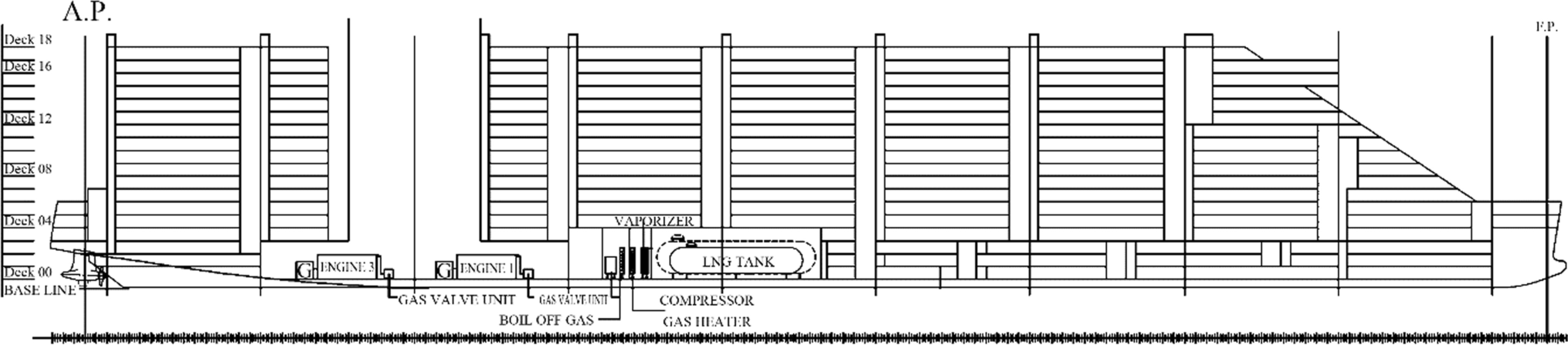 Figure 1 Basic general arrangement: vertical longitudinal section
 Figure 2 Basic general arrangement: deck 00 sectionTable 1 Main cruise ship characteristics
Passengers 6600 + 2035 crew members Main dimension (m) Length: 350–360; Breadth: 40–45; Height: 50–60 Design draught (m) 7.74 Decks 19 Cruise speed (kn) 19 (maximum: 21) Autonomy (h) 276, 214 (navigation mode) Propulsion Double propeller with gas engines Fuelling A complete fuel gas handling system for LNG fuelled ships Maximum power (MW) 61.6 The propulsion power and electrical power production are provided by four Wartsila Dual-fuel diesel/LNG engines (model: 18V50DF) coupled with ABB′ alternators which supply a nominal power of 17.55 MW at 60 Hz each. It is supposed that the alternator has an efficiency of about 96.5% and the generating sets (gen-set) work at 90.9% of their maximum power; as a consequence, the highest electrical load is 61.6 MW (Tronstad et al. 2017).
The ship complies the SOLAS regulation regarding the 'Safe Return to Port' (SRP) rule that considers a secure and autonomous return to port in case of damage to the power or fuel supply systems (IMO 2009). According to this, the ship presents two couples of generator sets arranged in two separate and completely independent compartments (machinery room 1 and 2) along with storage MGO fuel system that should be used in case of damage or malfunction of the LNG fuel system.
The cruise ship has three independent C-type LNG tanks (2 × 2000 m3 and 1 × 1500 m3) that guarantee an autonomy of 10 days and the SRP (IMO 2016).
2.2 Electrical Balance
The electrical distribution of the ship is based on an Integrated Power System (IPS) configuration (Patel 2011). A rough evaluation of the electrical loads on board has been carried out considering the electrical balance of other similar cruise ships. The total electrical load of the cruise ship (61.6 MW) is distributed among various main loads, which are reported in Table 2.
Table 2 Electrical loads subdivisionLoad Power (kW) Propulsion service 32, 032 Engine service, auxiliary 4312 Bow thrusters 1848 Conditioning and vent service 6160 Lighting service 4312 Safety service 924 Laundry service 1232 Galley service 5236 Water treatment service 3696 Other devices 1848 The hotel load comprises the galley, laundry, lighting, air conditioning and ventilation services, corresponding to 27.5% (16.94 MW) of the total load required on board (61.6 MW). This power demand can be provided entirely by a single gen-set installed on board.
2.3 Solid Oxide Fuel Cell
A literature and internet study were conducted to find specifics of SOFC plants, particularly regarding efficiency, weight, volume, installed capacity and emission factors. A database was constructed considering commercial hybrid SOFC products sold by worldwide companies, such as Mitsubishi Hitachi Power Systems (Japan), BloomEnergy (USA), Convion (Finland), SunFire GmbH and (Germany), Elcogen (Estonia) (Department of Energy 2015; McPhail et al. 2017; Hart et al. 2018).
Since SOFC technology specifications vary considerably depending on the application, the power size, type of fuel and reformer system, etc., the selected data considered only SOFC products suitable for stationary plants with power higher than 50 kW and fuelled by natural gas (NG). A schematic of a SOFC is shown in Figure 3 (McPhail et al. 2017; Breeze and Breeze 2019).
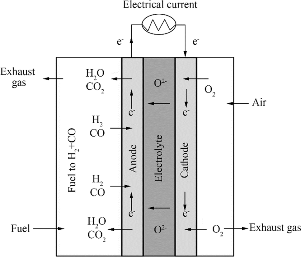 Figure 3 Schematic of a SOFC
State-of-the-art SOFC systems fuelled by NG provide an average electrical efficiency of around 60% (Gür 2016). Efficiency is related to the fuel flow rate (m) according to Eq. (1) (Breeze and Breeze 2019):
$$ {\eta}\text{=}\frac{{P}}{{m}\cdot \text{LHV}} $$ (1) where P is the electrical power and LHV is the lower heating value of LNG (≈50 MJ/kg).
Therefore, SOFC fuel consumption can be calculated by Eq. (1) according to the power demand.
2.4 Emissions
Emission factors depend strongly on engines specifics and the operating conditions which largely vary in consequence of the different applications. Therefore, a broad range of emissions factors has been reported in literature (Maji et al. 2008; Coppola and Quaranta 2014; Vávra et al. 2017; Zheng et al. 2019). In order to compare SOFC to DF engine, just for a rough evaluation, we considered average values and the variability range of emissions factors of DF engine depending only by the fuel consumption that are obtained from literature data. These values together with the standard deviations are reported in Table 3, considering only DF engines with emissions that respect the IMO tier Ⅱ regulations (Wik and Niemi 2016; Coppola et al. 2020a).
Table 3 Estimation of a dual-fuel engine (DF) and SOFC system emission factorsEmissions DF SOFC SOx (mg/kWh) 32 ± 17 Negligible NOx(mg/kWh) 7000 ± 2100 4.8 ± 0.2 CO (mg/kWh) 15, 000 ± 4230 2.1 ± 0.1 PM (mg/kWh) 175 ± 108 Negligible CO2 (g/kWh) 725 ± 234 343 ± 37 The SOFC system can be supposed to have lower emissions according to literature data. SOx emission is negligible due to the fact that sulphur compounds are poisons of the electro-catalysts into the SOFC and must be removed with an adequate clean-up system up to levels lower than 1 ppmv, which does not release any gaseous sulphur compounds (Micoli et al. 2014; Turco et al. 2016). PM emissions are also negligible because the electro-chemical conversion of a fuel into an FC does not produce PM as a by-product (Coralli et al. 2018). NOx and CO are emitted due to the high temperature; however, the concentrations obtained from SOFC are significantly lower than those of internal combustion engines (Kendall and Kendall 2015; Coralli et al. 2018; Mocerino et al. 2020) and are slightly affected by the power loads. Average values and standard deviations are calculated from literature data (Table 3). It must be noted that SOFC emission factors and the standard deviation ranges are lower than the corresponding DF engine values.
CO2 emission factors both for the gen-set and the SOFC plant are calculated from fuel consumption.
2.5 Floating and Trim
The introduction or removal of spaces and weights on board, which involves modifications of the original design, has to verify the stability of the ships. As a preliminary approach, this work considers the effect on introduction of an SOFC plan on board of the cruise ship in terms of floating and trim.
Generally, the floating of a ship considers two global forces acting on it, which are:
a) The weight (displacement), vertically downwards, which can be considered acting as a concentrated a centre of gravity (G), as for any rigid body;
b) The buoyancy, vertically upward, which can be assumed to be concentrated at the centre (B) of the underwater shape and volume (Lewis 1989).
When the ship is in calm water, the weight and buoyancy forces act in the same straight-line BG.
The installation of SOFC plant adds weight (W) on board, causing the following effects:
The ship undergoes a parallel sinkage, having buoyancy as equal as W and the centre of buoyancy moves towards the addition (BB′) according to Eqs. (2) and (3) (Lewis 1989):
$$ W\overset{\cdots\cdots\rightarrow}{\boldsymbol G\boldsymbol g}=(\Delta+w)\overset{\cdots\cdots\rightarrow}{\boldsymbol G\boldsymbol G^{\prime }} $$ (2) $$ W\overset{\cdots\cdots\rightarrow}{\boldsymbol B\boldsymbol b}=(\Delta+W)\overset{\cdots\cdots\rightarrow}{\boldsymbol B\boldsymbol B^{\prime }} $$ (3) where b is the centre of buoyancy of the added layer (volume) of buoyancy; g is the gravity acceleration; ∆ is the ship displacement; G′ is the new centre of gravity; B′ is the new centre of buoyancy.
The ship changes the mean draught and the trim according to the following equations (Lewis 1989):
$$ T_{m^{\prime }}=T_m+{\textstyle\frac W{\rho\;g\;A_{wl}}}+\frac{(x_\varnothing-x_F)}L(T_m-T_f) $$ (4) $$ \left({{T}}_{{a}}{-}{{T}}_{{f}}\right){=}\frac{\left({{x}}_{{W}}{-}{{x}}_{{F}}\right){W}}{\text{MCT}} $$ (5) $$ \text {MCT}=\frac{\left({\Delta }+W\right)\ G^{\prime }{M}_{L^{\prime }}}{L} $$ (6) where Tm' is the new mean draught after adding W; Tm is the initial mean draught; L is the ship length; ρ is the water density; Awl is the water plane area; Ta is the draught on the aft perpendicular; Tf is the draught on the forward perpendicular; $ {\text{x}}_{\oslash} $ is the longitudinal amidships; $ {\text{x}}_{\text{F}} $ is the longitudinal centre of floating; $ {\text{x}}_{\text{W}} $ is the longitudinal centre of the added weight; $ \text{G'}{\text{M}}_{\text{L'}} $ is the longitudinal metacentric height; MCT is the moment due to change of trim (Lewis 1989).
A simplification of the system made up by Eqs. (4), (5) and (6) is to apply the addition of a weight W which causes the sink and trim as follows (Lewis 1989):
1) The force W at the centre of floating causes a parallel sinkage $ \frac{{W}}{\rho \text{ g }{A}_{{wl}}} $;
2) The momentum $ \left({{x}}_{{W}}\text{-}{{x}}_{{F}}\right){W} $ causes a change of trim $ \frac{\left({{x}}_{{W}}\text{-}{{x}}_{{F}}\right){W}}{{\text MCT}} $.
2.6 Vertical Centre of Gravity on Keel Line
The calculation of the vertical centre of gravity on keel line (KG-limit) is required for the verification of stability of the intact state of passenger ships.
For conventional ships, the longitudinal stability is always high and need not be considered. It is necessary to consider circumstances during the life of the passenger ship which cause it to heel over i.e. the action of the wind on superstructures and the action of waves in rolling the ship (Lewis 1989).
To avoid the need for direct verification of the various standards on stability curves to be carried out on a case-by-case basis, the instruction manual for the captain must be completed with diagrams indicating the maximum allowable height of the centre of gravity of the ship at the various displacements. The centre of gravity of the ship (KG) at various displacements must always be below the vertical centre of gravity on keel line limit curve (KG-limit). This KG-limit curve is obtained considering the following 'intact standard stability criteria' for new passenger ships of 24 m in length and over, and literature procedures (Lewis 1989):
1) The area under the righting arm (GZ) curve shall not be less than:
2) 0.055 m rad up to 30°;
3) 0.09 m rad up to 40°or up to the down flooding angle;
4) 0.03 m rad between 30° and 40 or up to the down flooding angle.
5) GZ must be greater than 0.2 m at 30°.
6) Maximum GZ must be at an angle greater than 30°.
7) The minimum metacentric height (GM) must be at least 0.15 m.
8) Other criteria due to beam winds and rolling, heeling during a high-speed turn and crowding of passengers to one side of ship.
In the present study, the KG has been calculated after the installation on board of the SOFC plant and compared to the KG-limit to verify the stability of the cruise ship.
2.7 Case Study
In the present work, we examine the possibility of implementing an SOFC plant on board a cruise ship to supply the hotel loads entirely. It is supposed to replace a gen-set with an equivalent SOFC power plant (16.94 MW) integrated into the ship's IPS plant. In this preliminary study, we consider the SOFC plant as an independent box that produces only electrical power while being connected to the grid, requiring only the piping for the fuelling of evaporated LNG. We exclude a CHP configuration of the SOFC plant in order to avoid the introduction of other auxiliary devices on board, which increase weight and dimensions.
In this revised configuration, the other three generator sets must provide only the propulsion load (32.03 MW) and the remaining part of auxiliary power (12.63 MW), with a total power of 44.66 MW. This means that they will work at about 88% of their maximum power potential, which is still considered an optimal configuration in terms of performance and consumption for the generator sets.
3 Results
3.1 Dimensions and Weights
Results of data collection indicate that any information dealing with dimensions and weights of SOFC plants higher than 300 kW are available or declared by manufactures. As a consequence, volume and weight of a multi-MW SOFC plant are roughly estimated by linear regressions of the data of interest. These are shown in Figure 4 and involved only planar SOFC products since they appear more spread than the tubular ones (McPhail et al. 2017) and a comparison results more reasonable.
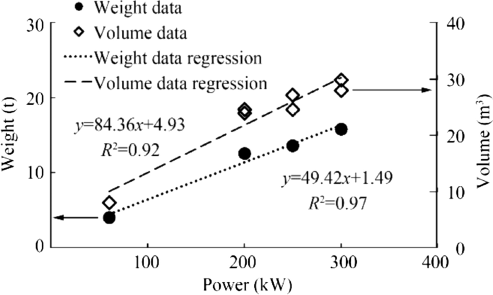 Figure 4 Distribution of weights and volumes versus power size of different SOFC plants
SOFC is a modular technology able to cover the power request by increasing or reducing the number of stacks or modules, but modularity cannot be valid for other components of the BoP. Assuming linear regression of weight and volume as a function of the power implies an error that can be as high as the power is outside the data range. In the present case study, the power size to be implemented on board is not part of the data range; however, we considered these values preventive and just for a preliminary investigation. Therefore, taking into account a 16.94 MW SOFC plant, the calculated volume and weight are 1434 m3 and 839 t, respectively.
It is worthy of note that in such an application of the SOFC system, the redundancy is not mandatory by regulations (Korean Register 2015; RINA 2018); as a consequence, any additional power is required.
On the other hand, it is mandatory to permit easy access to the SOFC and to each component of the plant in order to guarantee ease of maintenance and inspection (RINA 2018). Consequently, an additional volume must be considered all around the SOFC plant. Conventionally, a safe distance of 0.75 m from the perimeter and 0.50 m is assumed from the top to the superior deck (9 m is the total height of the room). According to these, it is supposed that the SOFC plant requires about 1892 m3 for the installation on board.
The dimensions and weight of a single gen-set are taken directly from the manufacturer guide (Coppola et al. 2020a); specifically, the considered gen-set has a volume of about 834 m3 and weighs 286 t. The four generator sets are located in two machinery rooms designed ad hoc, respecting international regulations.
3.2 Fuel Consumption
The total amount of the required LNG can be estimated considering the autonomy and the electrical balance of the cruise ship, assuming that the specific fuel consumption of the gen-set is constant (146 g/kWh). This can be done both for the traditional configuration and the case study. Results are reported in Table 4.
Table 4 LNG consumption prediction of the traditional configuration (DF) and the case study (SOFC)Load Weight (t) Volume (m3) DF SOFC DF SOFC Propulsion 1003 1003 2235 2235 Auxiliary 510 510 1137 1137 Hotels 684 608 1525 1356 Required LNG 2197 2121 4896 4727 Additional LNG (12%) 263 254 588 568 Total LNG 2460 2375 5484 5295 The case study considers that only the hotels load is supplied by the SOFC plant; therefore, the amounts of LNG required for the propulsion and the auxiliary services are the same. Since the SOFC has a higher efficiency, it consumes less LNG (608 t/1356 m3) than the gen-set (684 t/1525 m3) to supply the same amount of power (16, 394 kW). The total required LNG obtained from the electrical balance is about 2197 t (4896 m3) in the case of the traditional configuration and 2121 t (4727 m3) in the case of the implementation of the SOFC plant.
Taking into account that the LNG tanks cannot be filled more than up to 98% of their total volume for safety reasons (overfilling) (Korean Register 2015) and the ship has to arrive at port at least with 10% residual-fuel (IMO 2016; RINA 2018), it is considered an additional amount of LNG of 12%. As a consequence, the total LNG stored on board is 2460 t (5484 m3) for the traditional configuration and 2375 t (5295 m3) for the case study. It means that the SOFC plant allows for a saving of about 85 t (190 m3) of LNG per mission, corresponding to the 3.5% of the total stored LNG. It must be noted that this value increases considerably if we consider the real specific fuel consumption of the DF gen-set that is always higher, in place of the value specified by the manufacturer, assumed constant in the calculations of this work.
3.3 Emissions in Ports
The cruise ship stays in port 12 h per day and the power demand that should be covered is approximately equal to the hotel load. Assuming that in ports, the SOFC plant replaces the electrical power production of a single gen-set, it is possible to estimate the emission reduction by comparing the two technologies. The reference emissions data of SOFC and DF engine are those reported in Table 3. Average values are considered for DF engines and SOFC in order to give just a predictable emission reduction that can be potentially gained by replacing DF engine with SOFC. Results are reported in Table 5.
Table 5 Estimated emissions reduction by using the SOFC plant in place of a DF gen-setEmissions Reduction (%) SOx 100 NOx 99.93 CO 99.98 PM 100 CO2 11.11 Since the SOFC does not emit appreciable amounts of SOx and PM, these are reduced by 100%, thus giving a net benefit (Kendall and Kendall 2015; Coralli et al. 2018). NOx and CO emissions of a SOFC are at least three orders of magnitude lower than the gen-set giving a reduction of 99.93% and 99.98%, respectively. Emission of CO2 mainly depends on fuel consumption; therefore, it is reduced by about 11% thanks to the higher efficiency of the SOFC plant. As expected, results indicate that using an SOFC plant in place of a gen-set in ports allows for a significant reduction of global emissions in the ports visited by the cruise ship.
It is worthy of note that unburned methane emissions are one of the most concerning from DF engines; in the case of the SOFC plant, they have totally avoided thanks to the fuel conversion process inherent to the FC.
3.4 General Arrangements and Ship Stability
The case study deals with the installation on board of a SOFC plant to replace one of the four generator sets present on deck 00 of the ship (see Figures 1 and 2), but this involves a change of the layout of the basic general plane.
Specifically, the SOFC plant results heavier (839 t) and requires more volume (4892 m3) on board than a DF gen-set (286 t, 834 m3). On the other hand, it allows for the saving of about 85 t (190 m3) of LNG per mission.
A preliminary modification of the general arrangement of the cruise ship is proposed in Figures 5, 6 and 7.
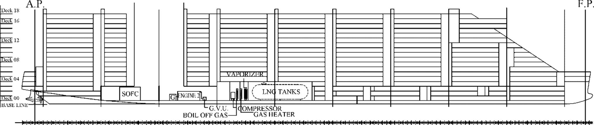 Figure 5 Basic general arrangement: vertical longitudinal section after installation of the SOFC plant
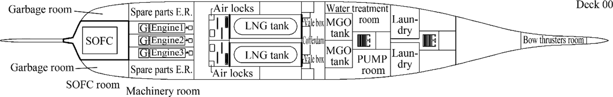 Figure 6 Basic general arrangement: deck 00 section after installation of the SOFC plant
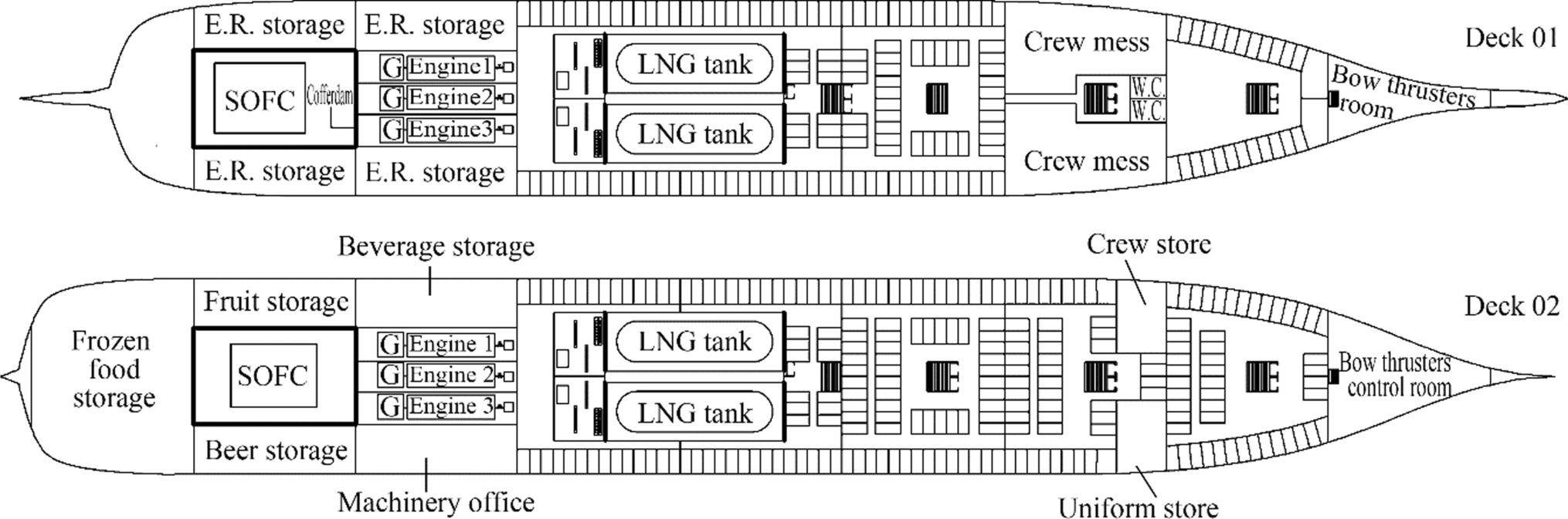 Figure 7 Basic general arrangement: deck 01 and deck 02 sections after installation of the SOFC plant
Two separated areas are proposed to host the power plants: a machinery room, subdivided into three equal compartments containing each a generator sets, and an SOFC room. These are in compliance with SOLAS regulations (IMO 2009) which ensure the SRP by inserting longitudinal bulkheads between the generator sets of the machinery room in order to create separate and completely autonomous compartments.
Thanks to the fuel saved by using the SOFC plant (about 3.5% per mission), it is possible replace the initial three independent C-type LNG tanks with two others, which are bigger, without affecting the ship's stability or changing the original location on board.
Replacing a gen-set with the SOFC plant implies that a weight (W) of about 553 t is added on board and the estimated displacement (∆) of the ship results 81, 310 t. As consequence, the calculated variation of the mean draught (Tm′ − Tm) is 3.65 cm while the trim variation is negligible.
The new displacement value of the KG-limit is 21.33 m while the KG is 20.36 m. Since the KG value results lower than the KG-limit, the ship continues to meet the stability requirements in its intact state.
It results that the installation of a multi-MW SOFC power plant on board a cruise ship does not affect the floating and stability of the ship since it represents a small fraction of the ship's displacement.
These effects of the SOFC system on the stability and floating can be extended to smaller cruise ships, on the condition that the location on board and the ratio volume and weight of SOFCs to the volume and weight of the ship are similar of the present case study. However, the ship shape affects the stability and further investigation should be conducted with a certain amount of 'trial and error' in case of smaller cruise ships. In addition, the available volume is lower and this may require additional changes of the general arrangement.
4 Conclusion
The present work studied the implementation of a 16.94 MW SOFC plant on board a cruise ship in order to supply the hotel loads. The SOFC plant replaced a DF gen-set powered by LNG and was integrated into the ship's IPS plant.
The integration of the SOFC technology on board led to significant environmental advantages in terms of emissions in port and in fuel consumption as well: it resulted that SOx, CO, NOx, PM emissions were reduced by more than 99.9% while CO2 emissions were reduced by about 11%, thanks to the lower fuel request. The amount of LNG was calculated according to the total installed power on board and complying the SOLAS regulation regarding the 'Safe Return to Port'.
The SOFC plant resulted heavier (839 t) and required more volume (4892 m3) on board than a DF gen-set (286 t, 834 m3). As a consequence, it involved modifications of the original design of the cruise ship and the verification of the floating and stability of the ship. It resulted that these parameters were not appreciably affected by the introduction of the SOFC plant.
A preliminary modification of the general arrangement of the cruise ship was also suggested, according to the latest international rules for the installation of fuel cell system on board.
It must be noted that data analysed in this study are those of SOFC stationary power plants and the designing did not consider any restrictions of weight and volume, which are an issue in the naval sector. Moreover, it is supposed that the SOFC technology will require adjustments to comply naval rules and standards.
Future works should improve the calculations conducted in this study as soon as the SOFC producers will update volume and weight data of commercial multi-MW plants. Moreover, ship design solutions must consider a waste heat recovery system appropriate for the SOFC plant that could allow to reduce further the fuel consumption and emissions.
Open Access This article is licensed under a Creative Commons Attribution 4.0 International License, which permits use, sharing, adaptation, distribution and reproduction in any medium or format, as long as you give appropriate credit to the original author(s) and the source, provide a link to the Creative Commons licence, and indicate if changes were made. The images or other third party material in this article are included in the article's Creative Commons licence, unless indicated otherwise in a credit line to the material. If material is not included in the article's Creative Commons licence and your intended use is not permitted by statutory regulation or exceeds the permitted use, you will need to obtain permission directly from the copyright holder. To view a copy of this licence, visit http://creativecommons.org/licenses/by/4.0/. -
Figure 1 Basic general arrangement: vertical longitudinal section
Figure 2 Basic general arrangement: deck 00 section
Figure 3 Schematic of a SOFC
Figure 4 Distribution of weights and volumes versus power size of different SOFC plants
Figure 5 Basic general arrangement: vertical longitudinal section after installation of the SOFC plant
Figure 6 Basic general arrangement: deck 00 section after installation of the SOFC plant
Figure 7 Basic general arrangement: deck 01 and deck 02 sections after installation of the SOFC plant
Table 1 Main cruise ship characteristics
Passengers 6600 + 2035 crew members Main dimension (m) Length: 350–360; Breadth: 40–45; Height: 50–60 Design draught (m) 7.74 Decks 19 Cruise speed (kn) 19 (maximum: 21) Autonomy (h) 276, 214 (navigation mode) Propulsion Double propeller with gas engines Fuelling A complete fuel gas handling system for LNG fuelled ships Maximum power (MW) 61.6 Table 2 Electrical loads subdivision
Load Power (kW) Propulsion service 32, 032 Engine service, auxiliary 4312 Bow thrusters 1848 Conditioning and vent service 6160 Lighting service 4312 Safety service 924 Laundry service 1232 Galley service 5236 Water treatment service 3696 Other devices 1848 Table 3 Estimation of a dual-fuel engine (DF) and SOFC system emission factors
Emissions DF SOFC SOx (mg/kWh) 32 ± 17 Negligible NOx(mg/kWh) 7000 ± 2100 4.8 ± 0.2 CO (mg/kWh) 15, 000 ± 4230 2.1 ± 0.1 PM (mg/kWh) 175 ± 108 Negligible CO2 (g/kWh) 725 ± 234 343 ± 37 Table 4 LNG consumption prediction of the traditional configuration (DF) and the case study (SOFC)
Load Weight (t) Volume (m3) DF SOFC DF SOFC Propulsion 1003 1003 2235 2235 Auxiliary 510 510 1137 1137 Hotels 684 608 1525 1356 Required LNG 2197 2121 4896 4727 Additional LNG (12%) 263 254 588 568 Total LNG 2460 2375 5484 5295 Table 5 Estimated emissions reduction by using the SOFC plant in place of a DF gen-set
Emissions Reduction (%) SOx 100 NOx 99.93 CO 99.98 PM 100 CO2 11.11 -
Baldi F, Moret S, Tammi K, Maréchal F (2020) The role of solid oxide fuel cells in future ship energy systems. Energy 194:116811. https://doi.org/10.1016/j.energy.2019.116811 Bouman EA, Lindstad E, Rialland AI, Strømman AH (2017) State-of-the-art technologies, measures, and potential for reducing GHG emissions from shipping – A review. Transp Res Part D Transp Environ 52:408–421. https://doi.org/10.1016/j.trd.2017.03.022 Breeze P, Breeze P (2019) Chapter 7 – Fuel cells. Power Gener Technol, 63–73. https://doi.org/10.1016/B978-0-08-102631-1.00007-9 Burel F, Taccani R, Zuliani N (2013) Improving sustainability of maritime transport through utilization of Liquefied Natural Gas (LNG) for propulsion. Energy 57:412–420. https://doi.org/10.1016/j.energy.2013.05.002 Choudhury A, Chandra H, Arora A (2013) Application of solid oxide fuel cell technology for power generation - a review. Renew Sustain Energy Rev 20:430–442. https://doi.org/10.1016/j.rser.2012.11.031 Christiansen N, Holm-Larsen H, Primdahl S et al (2019) Recent progress in development and manufacturing of SOFC at Topsoe Fuel Cell A/S and Riso̸ DTU. ECS Trans 35(1): 71–80. https://doi.org/10.1149/1.3569980 Cooper SJ, Brandon NP (2017) An introduction to solid oxide fuel cell materials, technology and applications. In: Solid Oxide Fuel Cell Lifetime and Reliability: Critical Challenges in Fuel Cells, 1–18 Coppola T, Micoli L, Turco M (2020a) Application of high temperature fuel cell powered by lng on a ferry-boat: a case study. In: Sustainable Development and Innovations in Marine Technologies - Proceedings of the 18th International Congress of the International Maritime Association of the Mediterranean, IMAM 2019 Coppola T, Micoli L, Turco M (2020b) State of the art of high temperature fuel cells in maritime applications. In: 2020 International Symposium on Power Electronics, Electrical Drives, Automation and Motion, SPEEDAM 2020, 430–435 Coppola T, Quaranta F (2014) Fuel saving and reduction of emissions in ports with cold ironing applications. X High Speed Marine Vehicles Coralli A, Sarruf BJM, De Miranda PE V., et al (2018) Fuel cells. In: Science and Engineering of Hydrogen-Based Energy Technologies: Hydrogen Production and Practical Applications in Energy Generation, 1–56 Department of Energy US (2015) Fuel cell technologies office multi-year research, development and demonstration plan 3.1 hydrogen production. Fuel Cell Technol Off Multi-Year Res Dev Demonstr Plant Ellamla HR, Staffell I, Bujlo P et al (2015) Current status of fuel cell based combined heat and power systems for residential sector. J Power Sources 293:312–328. https://doi.org/10.1016/j.jpowsour.2015.05.050 Guaitolini SVM, Yahyaoui I, Fardin JF, et al (2018) A review of fuel cell and energy cogeneration technologies. In: 2018 9th International Renewable Energy Congress, IREC 2018 Gür TM (2016) Comprehensive review of methane conversion in solid oxide fuel cells: prospects for efficient electricity generation from natural gas. Prog Energy Combust Sci 54:1–64. https://doi.org/10.1016/j.pecs.2015.10.004 Hart D, Lehner F, Jones S, et al (2018) The Review Industry Fuel Cell 2018. E4tech IMO (2009) SOLAS - International Convention for the Safety of Life At Sea IMO (2016) The International Code of Safety for Ships Using Gases or Other Low-Flashpoint Fuels (Igf Code) Kendall K, Kendall M (2015) High-Temperature Solid Oxide Fuel Cells for the 21st Century: Fundamentals, Design and Applications. 2nd edition Korean Register (2015) Guidance for Fuel Cell Systems on Board of Ship Lammons R, Baiche R, Bax M (2015) LNG as a fuel. In: International Gas Union World Gas Conference Papers. Lewis E V (1989) Principles of naval architecture second revision volume Ⅲ motions in waves and controllability Li G, Gou Y, Qiao J, Sun W, Wang Z, Sun K (2020) Recent progress of tubular solid oxide fuel cell: From materials to applications. J Power Sources 477:228693. https://doi.org/10.1016/j.jpowsour.2020.228693 Maji S, Pal A, Arora BB (2008) Use of CNG and diesel in CI engines in dual-fuel mode. In: SAE technical papers McCarthy JE (2010) Air pollution and greenhouse gas emissions from ships. In: Air Pollution and Ship Emissions McPhail SJ, Conti B, Kiviaho J (2017) The Yellow Pages of SOFC Technology - International Status of SOFC Deployment Micoli L, Bagnasco G, Turco M (2014) H2S removal from biogas for fuelling MCFCs: new adsorbing materials. Int J Hydrogen Energy 39(4): 1783–1787. https://doi.org/10.1016/j.ijhydene.2013.10.126 Mocerino L, Quaranta F, Rizzuto E (2020) Climate changes and maritime transportation: a state of the art. In: Technology and Science for the Ships of the Future - Proceedings 19th International Conference on Ship and Maritime Research Moseley PT (2001) Fuel cell systems explained. J Power Sources 93(1–2): 285. https://doi.org/10.1016/s0378-7753(00)00571-1 Patel MR (2011) Shipboard Electrical Power Systems RINA (2018) Rules for Fuel Cells Installation in Ships Shabri HA, Othman MHD, Mohamed MA, Kurniawan TA, Jamil SM (2021) Recent progress in metal-ceramic anode of solid oxide fuel cell for direct hydrocarbon fuel utilization: A review. Fuel Process Technol 212:106626. https://doi.org/10.1016/j.fuproc.2020.106626 Sharaf OZ, Orhan MF (2014) An overview of fuel cell technology: fundamentals and applications. Renew Sustain Energy Rev 32:810–853. https://doi.org/10.1016/j.rser.2014.01.012 Sharafian A, Blomerus P, Mérida W (2019) Natural gas as a ship fuel: assessment of greenhouse gas and air pollutant reduction potential. Energy Policy 131:332–346. https://doi.org/10.1016/j.enpol.2019.05.015 Smith TWP, Jalkanen JP, Anderson BA, Corbett JJ, Faber J, Hanayama S, O'Keeffe E, Parker SJL, Aldous L, Raucci C, Traut M, Ettinger S, Nelissen D, Lee DS, Ng SAA, Winebrake JJ, Hoen M, Chesworth S, Pandey A (2014) Third IMO GHG Study 2014 The European Parliament and the Council of the European Union (2012) Directive 2012/27/EU of 25 October 2012 on energy efficiency, amending directives 2009/125/EC and 2010/30/EU and repealing directives 2004/8/EC and 2006/32/EC Tronstad T, Høgmoen ÅH, Haugom GP, Langfeldt L (2017) Study on the use of fuel cells in shipping. Study Commissioned by European Maritime Safety Agency (EMSA) Turco M, Micoli L, Ausiello A (2016) Treatment of biogas for feeding high temperature fuel cells Van Biert L, Godjevac M, Visser K, Aravind PV (2016) A review of fuel cell systems for maritime applications. J Power Sources 327:345–364. https://doi.org/10.1016/j.jpowsour.2016.07.007 Vávra J, Bortel I, Takáts M, Diviš M (2017) Emissions and performance of diesel–natural gas dual-fuel engine operated with stoichiometric mixture. Fuel 208:722–733. https://doi.org/10.1016/j.fuel.2017.07.057 Vitta E (2010) Pollution from ships. In: Recueil Des Cours, Collected Courses, 162 (2007) Wik C, Niemi S (2016) Low emission engine technologies for future tier 3 legislations - options and case studies. J Shipp Trade 1:1–22. https://doi.org/10.1186/s41072-016-0009-z Zheng J, Wang J, Zhao Z et al (2019) Effect of equivalence ratio on combustion and emissions of a dual-fuel natural gas engine ignited with diesel. Appl Therm Eng 146:738–751. https://doi.org/10.1016/j.applthermaleng.2018.10.045