-
Abstract
This paper proposes and analyzes a novel heating coil bundle with the tubes arranged in a multi-level manner. The bundle generates a heated cargo large-scale circulation that enables a superposition of the circulation-driven forced convection on the buoyancy-driven natural convection, providing a more efficient mixed convection heat transfer mechanism. A simulation-based comparison of the proposed design and the conventional design is provided. The test case comprising an actual tank heating of an RMH 45 residual fuel oil by an 8-bar steam is simulated by a finite volume method and an OpenFOAM computational fluid dynamics software. The simulation results reveal that a 47.1% higher average heat transfer coefficient may be achieved, allowing a 32.0% reduction of the required heating coil area.-
Keywords:
- Coil bundle ·
- Cargo heating ·
- Circulation ·
- Mixed convection ·
- Finite volume method ·
- OpenFOAM
Article Highlights• The heating coil bundle position within the tank is of the utmost importance.• The heated fluid cross-flow velocity through the bundle mainly determines the quantity of the heat transferred.• Compact heating coil bundles reduce material, installation, and maintenance costs.• The proposed design behaves significantly better than conventional design. -
1 Introduction
Heating coils are a necessary piece of equipment in the majority of oil tankers. Their purpose is raising and maintaining of the tank content temperature to enable an economic tank discharge during the cargo offloading (Gunner 2002; Chen 1996; Zhao et al. 2019).
The tank heating coils are traditionally executed as a grid of steam-driven parallel tubes, evenly distributed all over the tank bottom. Sometimes, when enlarged quantity of tubes is required, the heating coils are arranged on two levels, one above the other. It is interesting to note that this concept has remained unchanged since the advent of the world tanker fleet.
The early works of van der Heeden and Mulder (1965), Couchman et al. (1966), Saunders (1968), and Akagi (1969) set out the fundamentals of the tanker cargo heating design. These studies provided the model and full-scale measurement results, as well as the heat transfer coefficient correlations. An extensive experimental study (Suhara 1970; Kurihara et al. 1972) comprising model-tank measurements, as well as the real tanker on-board measurements, enlighten the subject of crude oil heating. Akagi and coworkers studied other kinds of highly viscous cargoes, such as low-grade fuels and coal–oil mixtures (Akagi et al. 1985). Also, Akagi and Kato (1987) and Akagi and Uchida (1987) studied the influence of tanker rolling on the heat transfer within the tank. These latter works are also important due to the first implementations of the modern computational techniques by the finite difference method. The heating simulations presented opened a possibility to understand better the complex fluid flow and heat transfer processes within the cargo tanks. Unfortunately, more recent research results are not found.
Contrary to the lack of marine applications, significant progress is achieved in the oil onshore storage field, where the cylindrical floating roof tanks have taken place. Zhao et al. (2017) numerically investigated a temperature distribution and its relationship with the flow pattern within a tank. Sun et al. (2018) performed simulations to analyze the heating effect of differently structured coils. Yang et al. (2018) conducted an experimental work that clarified the oil temperature fluctuation concerning the tank regions and variable ambient conditions.
Nowadays, tanker cargo heating seems out of focus, despite the significant changes that have occurred recently. Firstly, due to the evolved regulations, the tanker structure arrangements have changed considerably by abandoning the risky and thermally inefficient single-hull concept and introducing a safer and thermally more efficient double-hull one. According to the present tanker design, all structural elements (frames, girders, and stiffeners) are disposed of out of the tank. The consequence is that modern tanks are enclosed by plain and clean surfaces (see Figure 1), with no obstructions that interfere with the flow of the cargo within the tank. Secondly, the advanced computing technologies that have emerged enable massive numerical simulations that were not feasible in the past. These two changes make it possible to revisit the tanker cargo heating process (Pivac and Magazinović 2015) and suggest a fresh, unconventional design (Magazinović 2018, 2019a, b, 2020).
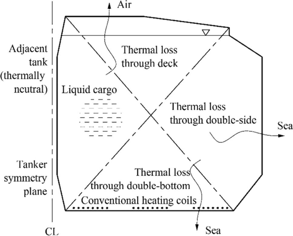 Figure 1 Tank cross-section: a problem scheme
The main outcome of Pivac and Magazinović (2015) is the discovery that heated cargo exhibits a powerful circular motion during the heating. This phenomenon permits a wholly new cargo heating concept based on utilizing the cargo circular motion for enhancing the coil heat transfer and obtaining a significant material and work-hour savings. This paper investigates the approach in more detail.
The paper is organized as follows. In Sect. 2, a brief description of the proposed heating coil approach is provided. Then, in Sect. 3, a detailed description of the computational fluid dynamics (CFD) simulation setups is given. The simulation results are provided and discussed in Sect. 4, wherein, in Sect. 4.3, the results evaluation by the alternative calculation procedures is provided. Finally, in Sect. 5, the conclusions of the study are summarized.
2 Multi-level Heating Coil Bundle
The proposed multi-level heating coil bundle design is based on the following concepts:
Tube Concentration Contrary to the conventional heating coils arrangements, the proposed design concentrates the heating coils into a slim and multi-level bundle, wherein the level is defined as a unique distance between the heating tube centerline and the bottom of the tank.
Asymmetric Placement The heating coil bundle is laid horizontally, close above the tank bottom, parallel to the vessel's longitudinal bulkhead, extended closer to the tank's inner side wall than its outer side wall.
Large-scale Circulation After a sufficient heating duration, the heated cargo circulates around the axis that is parallel to the heating tube centerlines.
Horizontal Cross-Flow The heated cargo cross-flows through the void space between the bundle tubes in a nearly horizontal direction.
Superimposing Forced on Natural Convection Owing to the superposition of the circulation-driven forced convection on the buoyancy-driven natural convection, the heat transfer mechanism upgrades to the more efficient mixed convection.
Clean, Compact Design The bundle arrangement features a small form factor, leaving the majority of the tank bottom free of the equipment or structural obstacles.
Simplified Cleaning, Survey, and Maintenance Free portions of the tank bottom are easy to clean when employing the crude oil washing system. Furthermore, the compact bundle simplifies periodic surveys, as well as the possible maintenance works.
Reduced Installation Workload The bundle features standard profile supports and two fittings only, requiring fewer work hours to install.
Figure 2 depicts a heating coil bundle satisfying the imposed design concepts. However, it should be noted that different embodiments are also possible.
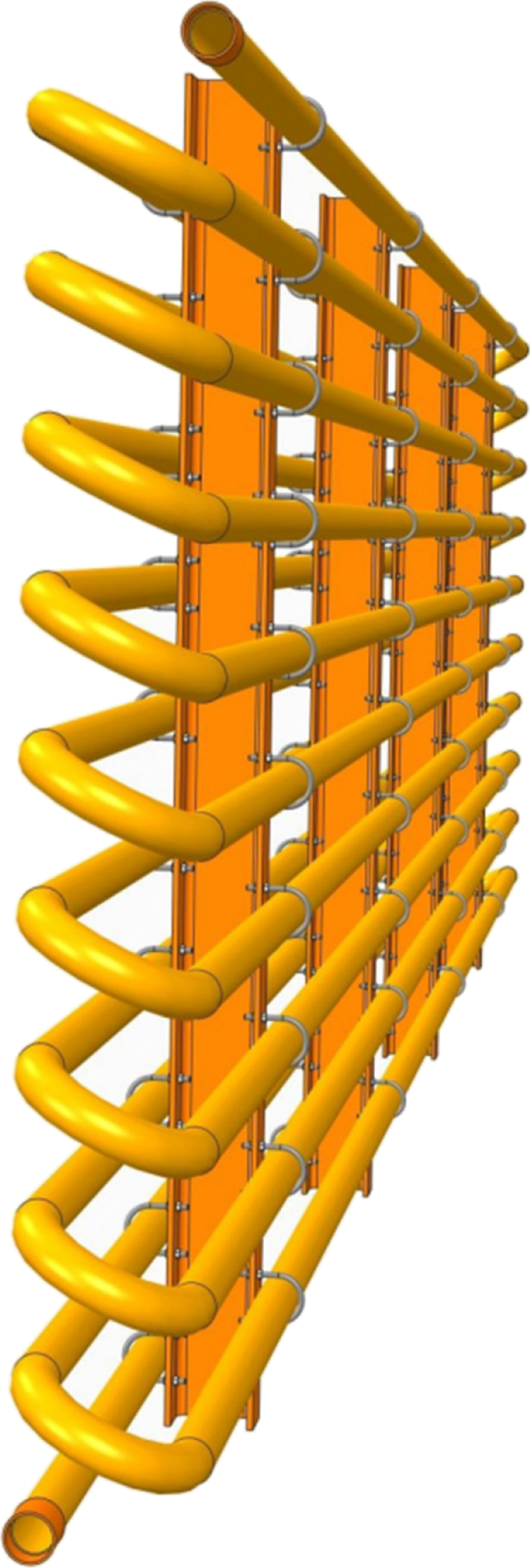 Figure 2 Proposed multi-level heating coil bundle
The heating coil bundle is characterized by a number of serially leakproof joined straight and U-shaped heating tubes, providing a coil grid with a steam inlet on the bundle top, and a condensate discharge on the bundle bottom. Heating tubes are connected to a number of supports by using U-shaped bolts and nuts, making a bundle a compact structure extended along the tank bottom.
A heating steam, generated in the tanker engine room and distributed over the deck level by the header and manifold, is supplied by a downcomer to the bundle steam inlet. On the bundle discharge side, a condensate lift is used to ensure a condensate-only return to the deck level discharge manifold and the return header. Since the steam advances through the bundle in a top-down direction, no water hammer–related difficulties should occur.
When one heating coil bundle is not sufficient to fulfill the tank-heating requirements, two or more heating coil bundles are needed. In that case, the bundles are aligned in a row along the tank bottom length.
The remaining sections of the paper are devoted to a simulation-based evaluation of the proposed design. A comparison with the conventional design is also provided.
3 Simulation Models
Two simulation models are built for the study. The first one encompasses the conventional heating coil design and the second one deals with the proposed bundle design.
The simulation models are based on the actual 65 000 dwt double-hull oil products tanker (Pivac and Magazinović 2015), wherein the model-tank particulars comprise a 7360 m3 capacity, 17.5 m breadth, 16.8 m height, 26.4 m length, and 15.4 m filling level (Figure 1).
The conventional heating coils are executed in the form of three heating coil blocks, comprising eight straight 50A-size (60.5 mm outer diameter) steel tubes each, arranged at 400 mm transverse pitch, 150 mm above the tank bottom. The void spaces between the blocks are 2.45 m wide.
The proposed heating coil bundle comprises a 20-level arrangement of 50A-size straight steel tubes, with both the transverse and longitudinal pitches of 181 mm, wherein the down-most tube is situated 90 mm above the tank bottom (Figure 2). Three coil bundles, positioned 7.5 m apart from the tank inner side wall, are laid along the tank bottom.
Both simulation models are set as a two-dimensional unsteady heat transfer and fluid flow driven by the action of the buoyancy forces. The simulations are performed by using the finite volume method, as implemented in OpenFOAM 3.0 CFD toolbox (Greenshields 2015).
3.1 Governing Equations
Governing equations fully describe the physical state of any part of the analyzed fluid domain. For the unsteady compressible flow, presented in vector notation, a set of governing equations comprise a mass conservation equation:
$$ \frac{\partial\rho}{\partial t}+\nabla{\;\cdot\;(\rho {\boldsymbol{U}})}=0, $$ (1) a momentum conservation equation:
$$ \frac{\partial\left(\rho {\boldsymbol{U}}\right)}{\partial t}+\nabla\;\cdot\;\left(\rho {\boldsymbol{UU}}\right)=\nabla\cdot\left\{\mu_{eff}\left[{\nabla {\boldsymbol{U}}+\left(\nabla {\boldsymbol{U}}\right)}^T\right]\right\}-\nabla\left[\frac23\mu_{eff}\left(\nabla\cdot {\boldsymbol{U}}\right)\right]-\nabla p+\rho {\boldsymbol{g}}, $$ (2) and an energy conservation equation, expressed in terms of the enthalpy h:
$$ \frac{\partial\left(\rho h\right)}{\partial t}+\nabla\cdot\left(\rho Uh\right)+\frac{\partial\left(\rho K\right)}{\partial t}+\nabla\cdot\left(\rho UK\right)-\frac{\partial p}{\partial t}=\nabla\cdot\left(a_{eff}\nabla h\right)+\rho U\cdot g, $$ (3) where ρ is the fluid density, t is the time, U is the velocity vector, μeff is the effective viscosity, p is the static pressure, g is the gravitational acceleration vector, K is the kinetic energy, and αeff is the effective thermal diffusivity.
By solving this system of equations, the pressure, enthalpy, and velocity vector components throughout the domain become available. Afterward, the remaining important parameters (e.g., temperature or heat transfer coefficients) may be determined.
3.2 Domain Discretization
Two two-dimensional meshes are generated for the study. A mesh representing a conventional heating coil design comprises 209 382 cells, mostly hexahedra with 242 prisms, whereas the mesh devoted to the proposed heating coil bundle design comprises 182 022 hexahedra and 264 prisms.
To determine the temperature gradients around the heating tubes accurately, coil boundary is meshed by 27 layers of cells, each layer comprising 120 cells, and the first layer thick 0.05 mm only. The tank enclosure is meshed by a four-layer boundary. All cell face lengths are smaller than 60 mm.
3.3 Model Setup
Both simulation tasks are set to heat the high-viscosity fuel oil for 5 h at the typical environmental conditions of an air temperature of 2 ℃ and a sea temperature of 5 ℃.
For simulation purposes, a 585 mm2/s nominal viscosity RMH 45 residual fuel oil was selected, with the thermal properties provided in Table 1. The fuel oil density, specific heat capacity, and thermal conductivity may be treated as linearly dependent on temperature. However, due to the high nonlinearity, in this study, the oil viscosity is approximated by a seventh-degree polynomial, as provided by Eq. (1) in Magazinović (2020). A heat flow model is assumed to be laminar.
Table 1 The RMH 45 (ISO 8217) residual fuel oil thermal properties used in the studyTemperature (℃) 55 157 Density (kg/m3) 964 893 Dynamic viscosity (Pa·s) 0.405 0.009 Specific heat capacity (J/kgK) 1870 2260 Thermal conductivity (W/mK) 0.130 0.106 Prandtl number 5830 180 The initial fuel oil temperature is 55 ℃, and the heating coil is driven by a 170.4 ℃ 8-bar saturated steam. A 165 ℃ maximum heating tube temperature is assumed. A 15 ℃ temperature difference between the tube cross-section upper-most and down-most circumferential points is assumed (Kurihara et al. 1972), resulting in a 157.5 ℃ mean heating coil temperature and the linear temperature distribution across the tube diameter. A schematic that further depicts this boundary condition has already been provided (see Figure 3 in Magazinović (2020)). The heating coils are additionally subjected to the cargo hydrostatic pressure and no-slip boundary conditions.
 Figure 3 Isotherms and velocity vectors for the conventional heating coil design case (the cargo circulation is emerging)
The heat supplied by the heating coils is mostly used for cargo heating. However, a part of the energy is released to the environment due to the tank wall convective heat outflows. The tank bottom and deck heat transfer coefficients are assumed as 3.2 W/m2K, Jandrijević et al. (2007), while the tank outer wall heat transfer coefficient is assumed as 3.3 W/m2K, Jandrijević et al. (2007). The tank inner side wall is taken as thermally neutral, i.e., no heat transfer is assumed.
Tank walls are modeled by the no-slip boundary conditions and the cargo hydrostatic pressure, whereas the upper cargo boundary, actually subjected to the open atmosphere, is modeled by zero total pressure and the two-way flow free velocity definition.
3.4 Software Setup
For simulation purposes, a buoyantPimpleFoam solver (Greenshields 2015) is selected. It is a segregated, pressure-based solver for compressible buoyancy-driven fluid flows that merges the PISO and SIMPLE algorithms (Moukalled et al. 2016). Since it is a transient solver, for time discretization, a Euler implicit method is used. For the gradients and Laplacian discretization, Gauss linear and Gauss linear–corrected schemes are applied, respectively, while a Gauss vanLeer interpolation method is selected for the convective term discretization.
The software setup comprises five PIMPLE iterations per time step, each iteration comprising two correction steps and two non-orthogonality correction steps. To solve the pressure equation, a PCG solver is used with the DIC preconditioner and the 10−8 tolerance. For the momentum and energy equations, a PBiCG solver is used with the DILU preconditioner and the 10−6 tolerance.
Residual control is governed by a 10−4 absolute tolerance. All the iterations except the final ones are stabilized by the under-relaxation factors of 0.7 for the pressure and 0.3 for the velocity and enthalpy.
For the simulation-time advancement, variable-size time steps are used, governed by a maximum Courant number set to 0.5 throughout the simulations. At each time step, after determining the fluid temperature, the PIMPLE solver invokes a thermophysical module to update properties as needed.
4 Results
The results presented herein encompass two cargo heating simulations. The first simulation results, provided in Sect. 4.1, relate to the conventional heating coil design and establish a baseline for the comparison. The second simulation results, presented in Sect. 4.2, delineate the performance of the proposed multi-level heating coil bundle (see Figure 2). Both simulations start with the cargo at the rest condition and share the same boundary conditions and simulation parameters. The initial time step size is set to 10−4 s.
4.1 Conventional Design
During the first few minutes of heating, each heating coil acts independently of each other. However, afterward, the eight plumes of each of the three heating coil blocks (see Figure 1) unite in a larger plume. Initially, the plumes move vertically upwards, generating the swirls throughout the lower part of the tank. Due to the continued input of the heat energy, the swirls gradually occupy the whole tank, causing the entire tank content to move. Although the fluid motion is initially chaotic, the later flow pattern gradually takes the form of a large-scale circulation (Krishnamurti and Howard 1981; Sreenivasan et al. 2002; Xi et al. 2006), as depicted in Figure 3. This phase of the tank fluid flow may be arbitrarily entitled as a pre-circulation phase. After around 2700 s of tank heating, the large-scale circulation is fully developed, denoting the start of the circulation phase of the tank fluid flow.
The fluid flow and heat transfer processes within the tank are rendered in more detail in Figures 4, 5, and 6.
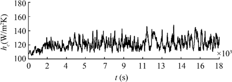 Figure 4 Heat transfer coefficient for the conventional heating coil design case
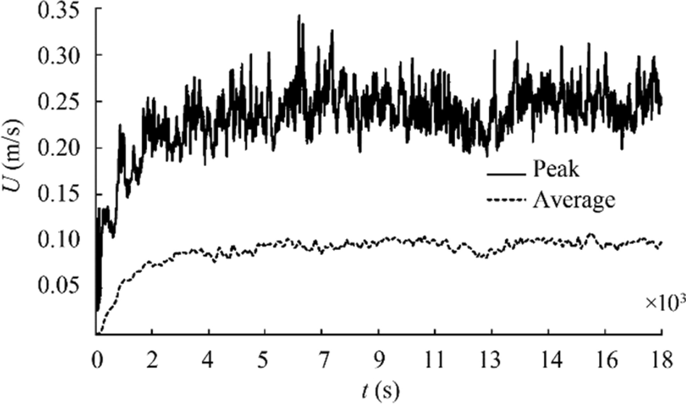 Figure 5 Cargo velocity for the conventional heating coil design case
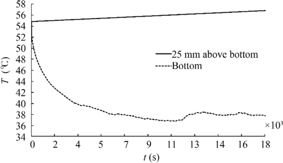 Figure 6 Cargo temperature for the conventional heating coil design case
Figure 4 shows a time variation of the heating coil surface area–averaged heat transfer coefficient. The area-averaged coefficient of coil surface heat transfer is defined by:
$$ {h}_{c}=\frac{{Q}_{c}}{{A}_{c}\left({T}_{c}-{T}_{b}\right)} $$ (4) where Qc is the coil heat flux (determined offline by an OpenFOAM wallHeatFlux utility), Ac is the coil area, and Tc and Tb are the coil surface and bulk oil temperatures, respectively.
During the pre-circulation phase, the coil heat transfer coefficient hc fluctuates between the initial 98.7 W/m2K and final 131.3 W/m2K, with the time-averaged value of 115.3 W/m2K. During the circulation phase, the heat transfer coefficient fluctuates around the time-averaged value hc = 121.3 W/m2K (a 5.2% rise in comparison with the pre-circulation phase average).
A rising trend of the heat transfer coefficient may be attributed to the raising trends of the peak and average fluid velocities (see Figure 5) during the same time frame. The peak velocity is defined as the maximum velocity amplitude determined in any of the cells within the domain, whereas the average velocity represents the velocity magnitude averaged over all domain cells.
The cargo temperature variation by time is provided in Figure 6, where the full-lineweight line refers to an average cargo temperature of 25 mm above the tank bottom, and the dotted line renders an average cargo temperature at the tank bottom. The bulk cargo temperature steadily rises from the initial 55 ℃ to the final 56.8 ℃, whereas the minimum cargo temperature at the tank bottom is 36.8 ℃, at t = 11 020 s.
The convective heat loss through the tank boundary at the end of the simulation totals Qloss = 164.4 kW, wherein the tank bottom heat outflow accounts for 41.5 kW.
4.2 Proposed Design
When the cargo large-scale circulation is concerned, the proposed coil bundle design case behaves similarly to the conventional heating coil design case. During the pre-circulation phase, the warm cargo plume moves upward, causing swirls in the upper tank zone (Figure 7). As the heating continues, the swirls become larger, gradually overtaking the whole tank. Afterward, a multiple of swirls gradually transforms into a single large-scale circulation, which results in a nearly horizontal cross-flow of the heated cargo through the void space between the bundle tubes (Figure 8).
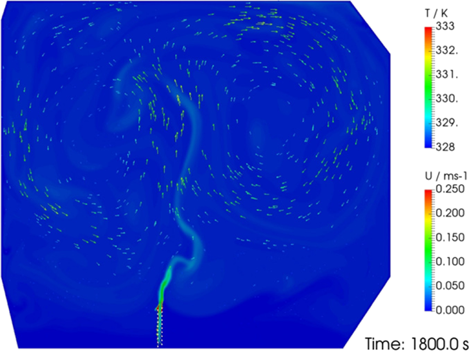 Figure 7 Isotherms and velocity vectors for the proposed heating coil bundle design case (pre-circulation phase)
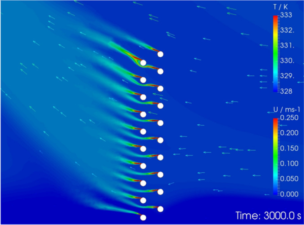 Figure 8 Isotherms and velocity vectors for the proposed heating coil bundle design case (circulation phase)
As in the conventional design case, the proposed design pre-circulation phase span is 2700 s, during which the bundle heat transfer coefficient, averaged over 20 heating coils, fluctuates around the average value of 147.4 W/m2K (Figure 9). Afterward, in the circulation phase, the bundle heat transfer coefficient fluctuates around an uprated average value of hc = 178.4 W/m2K (a 21.2% rise in comparison with the pre-circulation phase average). It should be noted that the high fluctuations presented in Figure 9 result from the flow pattern within the tank. Also, these fluctuations do not attenuate over time. The proposed design behaves significantly better than conventional designs. Such improvement is attributed to the enhanced fluid flow around the proposed bundle heating tubes. Large-scale circulation, which is responsible for the cross-flow, is mostly generated by the bundle in the asymmetric transverse position within the tank. The temperature difference between the outer and inner tank side walls further aids circulation.
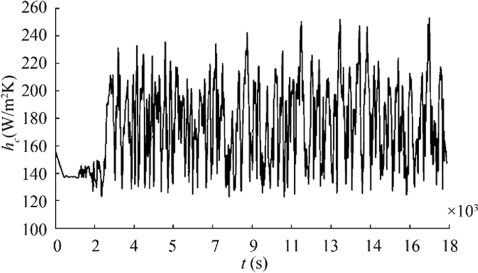 Figure 9 Heat transfer coefficient for the proposed heating coil bundle design case
A graphical representation of the heated cargo peak and average velocity magnitudes is provided in Figure 10. During the pre-circulation phase, the peak velocity tops at 0.264 m/s and averages 0.189 m/s. In the same time frame, the average velocity tops at 0.076 m/s and averages 0.044 m/s. Compared with the conventional heating coil design case, the average peak velocity is 6.8% higher, while the average velocity is 24% lower. During the circulation phase, the peak velocity tops at 0.322 m/s and averages 0.231 m/s, 4.9% lower than the conventional design case average of 0.243 m/s. The average velocity tops at 0.095 m/s and averages 0.085 m/s, 10.5% lower than the conventional design case average of 0.095 m/s. The general fall of the velocity readings may be attributed to the heating coil bundle that opposes the cargo free flow.
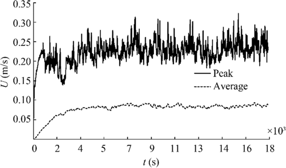 Figure 10 Cargo velocity for the proposed heating coil bundle design case
The heating coil bundle divides the tank's bottom part into two unequal regions: a larger inflow region, and a smaller outflow region (Figure 7). Whereas the flow pattern in the inflow region follows the behavior shown in the tank's upper part, the flow pattern in the outflow region behaves slightly differently; a less-intensive auxiliary circulation arises with the opposite rotation. To depict the difference between the outflow and inflow regions, the oil velocity was calculated at two probes, positioned 5.825 m and 11.075 m off the tank's inner side wall and 150 mm above the bottom of the tank. The velocity at the inflow region probe averaged 0.030 m/s and peaked at 0.101 m/s. The velocity at the outflow region probe averaged 0.012 m/s and peaked at 0.072 m/s.
To quantify the heating coil bundle cross-flow velocity, magnitudes of the cargo flow velocity at three probe points are recorded and analyzed. The probe points are chosen at half of the bundle height, at the levels of the Entrance, Middle, and Exit points of 993, 1038, and 1083 mm, respectively, counted from right to left (Figure 8). While the Entrance and Exit points are aligned with the tube column centerlines, the Middle point is situated in-between. The velocity readings at the Entrance point are graphed in Figure 11, whereas the complete set of the readings is summarized in Table 2.
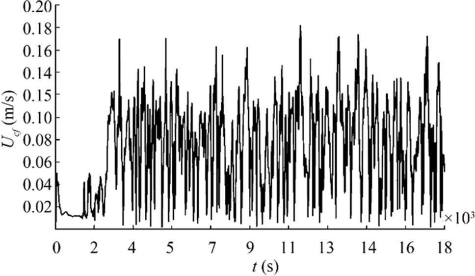 Figure 11 Entrance cross-flow velocity determined at half of the bundle heightTable 2 Cross-flow velocity at half of the bundle height
Probe location Maximum (m/s) Average (m/s) Entrance (bundle right hand side) 0.182 0.079 Middle 0.171 0.062 Exit (bundle left hand side) 0.176 0.075 The dimensionless Richardson number, Ri = Gr/Re2, where Gr and Re are the Grashof and Reynolds numbers, respectively, is a heat transfer regime characterization criterion. Namely, Ri > > 1 denotes a natural convection, Ri < < 1 represents a forced convection, and Ri ≈ 1 indicates a mixed convection. By using Table 2 data, it is found that the minimum and average Richardson numbers are 1.3 and 7.9, respectively. These values denote a mixed convention with the variable contribution of the forced convection. While Ri = 1.3 indicates a comparable impact, Ri = 7.9 represents a dominant natural convection.
A strong correlation is found between the peaks of the entrance cross-flow velocity (Figure 11) and the bundle heat transfer coefficient (Figure 9). When the entrance cross-flow velocity is at a local minimum, the heat transfer coefficient is also at a local minimum, and the high Richardson number indicates a natural convection. Alternatively, when the entrance cross-flow velocity is at a local maximum (the low Richardson number denotes a significant forced convection component), the heat transfer coefficient is also at a local maximum.
A time variation of the cargo temperature is provided in Figure 12. At the tank bottom, the average temperature minimum, attained at t = 17, 300 s, is 34.7 ℃, 2.1 ℃ lower than in the case of the conventional coil design. This temperature indicates a slightly inferior behavior regarding the possibility of the cargo components settling and solidification. However, as heating proceeds, temperature eventually rises. During the 5-h heating, the bulk cargo temperature averaged 25 mm above the tank bottom, steadily rising from the initial 55 ℃ to the final 57.1 ℃. The temperature rise of 2.1 ℃ is achieved by 20 heating tubes. For the reference, in the conventional heating coil design case, a 1.8 ℃ temperature rise is attained by 24 heating tubes.
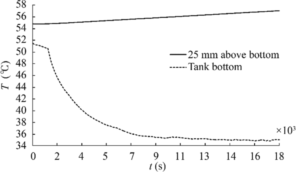 Figure 12 Cargo temperature for the proposed heating coil bundle design case
This study has revealed that intensive fluid mixing occurs within the tank. Calculations show that the fluid temperature in any part of the domain, except the boundary layers, differs by less than 0.4 ℃.
After heating for 5 h, the heat loss through the tank bottom is equal to 41.5 kW, and the tank total convective heat outflow reaches Qloss = 163.8 kW. Both results are comparable with the conventional heating coil design case values. The proposed and conventional designs behave almost identically, since the oil-flow characteristics on the outer tank boundary are virtually unchanged.
4.3 Results Evaluation
The conventional coil heat transfer coefficient results, as outlined in Sect. 4.1, are evaluated by employing Akagi's classic equation (Akagi 1969):
$$ {h}_{c}=0.515\left(k/d\right){Ra}^{0.25}{\left(\mu /{\mu }_{c}\right)}^{0.21} $$ (5) where k is the cargo thermal conductivity, d is the outer coil diameter, Ra is the Rayleigh number, and μ and μc are the cargo dynamic viscosities determined at bulk cargo and coil surface temperatures, respectively.
By using the cargo data of Table 1, Eq. (5) predicts a natural convection heat transfer coefficient of 116.2 W/m2K. This value is comparable with the pre-circulation phase time-average of 115.3 W/m2K (a − 0.77% difference). It is important to note that the circulation phase time-average heat transfer coefficient of 121.3 W/m2K should not be evaluated by the Akagi equation since the latter is based on the natural convection heat transfer mechanism only.
The proposed heating coil bundle results for the heat transfer coefficient, as presented in Sect. 4.2, are evaluated by employing the Gnielinski approach (Gnielinski 2010). The procedure of Gnielinski is based on the forced convection heat transfer mechanism, since the Nusselt number is defined as a function of the coil bundle geometry and Reynolds and Prandtl numbers. For the Reynolds number calculation, the average cross-flow velocity Ucf and streamed tube length l are relevant:
$$ Re=U_{\mathrm{cf}}\cdot l/v $$ (6) $$ l=d\cdot{\mathrm{\pi}}/2 $$ (7) where ν is the cargo kinematic viscosity.
Taking into account that for the laminar flow between parallel planes the mean velocity is two-thirds of the maximum value (Massey 1979), the average cross-flow velocity Ucf is determined by:
$$ U_{cf}=\left(U_{\mathrm{ent}}+U_{\mathrm{ext}}\right)/3 $$ (8) where Uent and Uext are the entrance and exit cross-flow velocities, respectively, as provided in Table 2.
By using data from Table 2, the two characteristic values of the heat transfer coefficient are determined and provided in Table 3. The results reveal, besides a comparable agreement with the CFD results, a strong relationship between the cross-flow velocity and the bundle heat transfer coefficient. Furthermore, the cargo cross-flow velocity is proven to be the most important parameter in determining the coil bundle overall heat output. However, it is important to note that the pre-circulation phase of the proposed bundle heating should not be evaluated by the Gnielinski method, since the initial fluid flow is in the vertical direction (Figure 7).
Table 3 Comparison of the circulation phase heat transfer coefficient determined by this study and the procedure of Gnielinski (2010)Heat transfer coefficient Ucf (m/s) This study (W/m2K) Gnielinski (W/m2K) Average 0.052 178.4 188.0 Maximum, at t = 17 205 s 0.119 253.7 284.5 4.4 Required Heating Coil Area
The required heating coil area Ac may be determined by iteration from the energy balance equation (Magazinović 1987):
$$ \ln\frac{h_cA_c\left(T_c-T_1\right)-Q_{\mathrm{loss}}}{h_cA_c\left(T_c-T_2\right)-Q_{\mathrm{loss}}}-\frac{h_cA_ct_{\mathrm h}}{{mc}_{\mathrm p}}=0 $$ (9) where T1 and T2 are the cargo initial and final temperatures, respectively, th is the heating duration, m is the cargo mass, and cp is the cargo-specific heat capacity at constant pressure.
For the cargo 4-day heating from 44 to 66 ℃ temperature, the required heating coil area calculation results are provided in Table 4. To achieve these results, the average heat transfer coefficients hc, determined in Sections 4.1 and 4.2, are used in Eq. (9).
Table 4 Comparison of the required heating coil areaCoil arrangement hc (W/m2K) Ac (m2) Normalized Ac Conventional design 121.3 82.14 1.00 Proposed design 178.4 55.82 0.68 5 Discussion
To check the results mesh-size independence, a procedure recommended by Celik et al. (2008) is applied.
Two coarser meshes, measuring 112 965 and 65 703 cells, are generated and tested. The corresponding circulation-phase average heat transfer coefficients are 176.4 W/m2K and 182.1 W/m2K, respectively. Under the apparent order p = 3.99, the following error estimates are recorded: an approximate relative error of 1.1%, an extrapolated relative error of 0.7%, and a fine-grid convergence index of 0.9%.
The calculations presented are characterized by an excessive simulation time, primarily due to a compressible, pressure-based problem formulation. Significant simulation-time reductions may be achieved by applying the Boussinesq approximation. However, since the Boussinesq approximation neglects the dynamic viscosity and thermal conductivity changes with temperature, significant errors may be introduced. For example, Bazdidi-Tehrani et al. (2018) reported deviations of up to 33% and 45% in Nusselt number's assessment. Therefore, a more demanding and general compressible formulation is retained herein.
Initially, both the laminar and the turbulent heat flow models were considered for the large-scale circulation phase simulation. Since the RNG k-epsilon turbulence model grossly overestimated the heat transfer coefficient values provided in Table 3, a more conservative laminar flow model is adopted in the present study.
6 Conclusions
In this paper, a novel heating coil bundle with the tubes arranged in a multi-level manner is proposed and analyzed. The bundle is characterized by a compact, small form-factor design that occupies a minimal tank bottom area. In addition, two fittings per bundle ensure an improved installation process.
The bundle generates a heated cargo large-scale circulation that enables a superposition of the circulation-driven forced convection on the buoyancy-driven natural convection, providing a more efficient mixed convection heat transfer mechanism.
Performed numerical simulations have shown that in the case of an RMH 45 residual fuel oil heating by an 8-bar steam, a 47.1% higher average heat transfer coefficient may be achieved, allowing a 32.0% reduction of the required heating coil area.
-
Figure 1 Tank cross-section: a problem scheme
Figure 2 Proposed multi-level heating coil bundle
Figure 3 Isotherms and velocity vectors for the conventional heating coil design case (the cargo circulation is emerging)
Figure 4 Heat transfer coefficient for the conventional heating coil design case
Figure 5 Cargo velocity for the conventional heating coil design case
Figure 6 Cargo temperature for the conventional heating coil design case
Figure 7 Isotherms and velocity vectors for the proposed heating coil bundle design case (pre-circulation phase)
Figure 8 Isotherms and velocity vectors for the proposed heating coil bundle design case (circulation phase)
Figure 9 Heat transfer coefficient for the proposed heating coil bundle design case
Figure 10 Cargo velocity for the proposed heating coil bundle design case
Figure 11 Entrance cross-flow velocity determined at half of the bundle height
Figure 12 Cargo temperature for the proposed heating coil bundle design case
Table 1 The RMH 45 (ISO 8217) residual fuel oil thermal properties used in the study
Temperature (℃) 55 157 Density (kg/m3) 964 893 Dynamic viscosity (Pa·s) 0.405 0.009 Specific heat capacity (J/kgK) 1870 2260 Thermal conductivity (W/mK) 0.130 0.106 Prandtl number 5830 180 Table 2 Cross-flow velocity at half of the bundle height
Probe location Maximum (m/s) Average (m/s) Entrance (bundle right hand side) 0.182 0.079 Middle 0.171 0.062 Exit (bundle left hand side) 0.176 0.075 Table 3 Comparison of the circulation phase heat transfer coefficient determined by this study and the procedure of Gnielinski (2010)
Heat transfer coefficient Ucf (m/s) This study (W/m2K) Gnielinski (W/m2K) Average 0.052 178.4 188.0 Maximum, at t = 17 205 s 0.119 253.7 284.5 Table 4 Comparison of the required heating coil area
Coil arrangement hc (W/m2K) Ac (m2) Normalized Ac Conventional design 121.3 82.14 1.00 Proposed design 178.4 55.82 0.68 -
Akagi S (1969) Heat transfer in oil tanks of ships. Japan Shipbuild Mar Eng 4(2): 26–35 Akagi S, Kato H (1987) Numerical analysis of mixed convection heat transfer of a high viscosity fluid in a rectangular tank with rolling motion. Int J Heat Mass Transf 30(11): 2423–2432 https://doi.org/10.1016/0017-9310(87)90232-8 Akagi S, Takemura M, Uchida K (1985) Natural convection heat transfer in tank-heating of high viscous oils including a low grade fuel and a coal oil mixture (COM). Bull MESJ 13(1): 4–18 https://trid.trb.org/view.aspx?id=420597 Akagi S, Uchida K (1987) Fluid motion and heat transfer of a high-viscosity fluid in a rectangular tank on a ship with oscillating motion. J Heat Transf Trans ASME 109(635): 641 Bazdidi-Tehrani F, Moghaddam S, Aghaamini M (2018) On the validity of Boussinesq approximation in variable property turbulent mixed convection channel flows. Heat Transf Eng 39(5): 473–491. https://doi.org/10.1080/01457632.2017.1312902 Celik IB, Ghia U, Roache PJ, Freitas CJ, Coleman H, Raad PE (2008) Procedure for estimation and reporting of uncertainty due to discretization in CFD applications. J Fluids Eng 130(7): 078001 https://doi.org/10.1115/1.2960953 Chen BCM (1996) Cargo oil heating requirements for an FSO vessel conversion. Mar Technol 33(1): 58–68 https://onepetro.org/MTSN/article/33/01/58/176041/Cargo-Oil-Heating-Requirements-for-an-FSO-Vessel Couchman AAJ, Dowie WF, McClimont W (1966) Heating of high-viscosity oil cargoes. Trans Inst Mar Engineers 78: 53–71 Gnielinski V (2010) Heat transfer in cross-flow around single rows of tubes and through tube bundles. In: VDI-GVC (eds), VDI Heat Atlas, Springer, Berlin, pp 725–729 Greenshields CJ (2015) OpenFOAM: the open source CFD toolbox, OpenFOAM Foundation, Bracknell, Great Britain, User Guide, Version 3.0.1 Gunner TJ (2002) Physical behavior of crude oil during transportation and its impact on the carriage of crude oil by sea. Mar Technol 39(4): 256–265 https://trid.trb.org/view/626903 Jandrijević B, Mrakovčić T, Račić R (2007) Analysis of heat transfer in ships' cargo tanks. Strojarstvo 49: 225–231 Krishnamurti R, Howard LN (1981) Large-scale flow generation in turbulent convection. Proc Natl Acad Sci USA 78(4): 1981–1985 https://doi.org/10.1073/pnas.78.4.1981 Kurihara T, Amagata H, Maekawa C (1972) Experimental studies on heat transfer coefficients and effective length of tank heating coils in vessels. Selected Papers J SNAJ 10: 129–144 https://trid.trb.org/view.aspx?id=5388 Magazinović G (1987) Computer aided design and analysis of tank heating. Brodogradnja 35(4–5): 193–202 ((in Croatian)) Magazinović G (2018) Cargo tank heating using vertically arranged heating coils. SORTA 2018, Split, Croatia, 349–356 Magazinović G (2019a) Vertical arrangement of coils for efficient cargo tank heating. Int J Nav Arch Ocean Eng 11(2): 662–670. https://doi.org/10.1016/j.ijnaoe.2019.02.004 Magazinović G (2019b) Multi-level heating coil bundle. China Patent Application CN110325437 A Magazinović G (2020) Circulation-enhanced tank heating using shallow profile coil bundles. J Mar Sci Appl 19(2): 234–245. https://doi.org/10.1007/s11804-020-00149-z Massey BS (1979) Mechanics of fluids, 4th edn. Van Nostrand Reinhold, New York, p 152 Moukalled F, Mangani L, Darwish M (2016) The finite volume method in computational fluid dynamics: an advanced introduction with OpenFOAM and Matlab. Springer, Cham, Switzerland. https://doi.org/10.1115/1.2960953 Pivac I, Magazinović G (2015) Numerical analysis of tank heating coil heat transfer process. In: Guedes Soares C et al (eds) Towards Green Marine Technology and Transport. Taylor & Francis Group, London, pp 603–608 Saunders RJ (1968) Heat losses from oil-tanker cargoes. Trans Inst Mar Eng 90: 405–414 Sreenivasan KR, Bershadskii A, Niemela JJ (2002) Mean wind and its reversal in thermal convection. Phys Rev E 65(5): 056306. https://doi.org/10.1103/PhysRevE.65.056306 Suhara J (1970) Studies of heat transfer on tank heating of tankers. Jpn Shipbuild Mar Eng 5(1): 516 Sun W, Cheng Q, Zheng A, Gan Y, Gao W, Liu Y (2018) Heat flow coupling characteristics analysis and heating effect evaluation study of crude oil in the storage tank different structure coil heating processes. Int J Heat Mass Transf 127: 89–101. https://doi.org/10.1016/j.ijheatmasstransfer.2018.08.035 van der Heeden DJ, Mulder LL (1965) Heat-transfer in cargotanks of a 50, 000 dwt tanker. Int Shipbuild Prog 12(132): 309–328 https://doi.org/10.3233/ISP-1965-1213201 Xi HD, Zhou Q, Xia KQ (2006) Azimuthal motion of the mean wind in turbulent thermal convection. Phys Rev E 73(5): 056312. https://doi.org/10.1103/PhysRevE.73.056312 Yang L, Zhao J, Dong H, Liu J, Zhao W (2018) Research on temperature profile in a large scaled floating roof oil tank. Case Stud Therm Eng 12:805–816. https://doi.org/10.1016/j.csite.2018.10.009 Zhao J, Dong H, Wang X, Fu X (2017) Research on heat transfer characteristic of crude oil during the tubular heating process in the floating roof tank. Case Stud Therm Eng 10:142–153. https://doi.org/10.1016/j.csite.2017.05.006 Zhao W, Zhao J, Si M, Liu J (2019) Thermal characteristics of waxy crude oil during its static cooling in an overhead pipeline. Case Stud Therm Eng 14:100475. https://doi.org/10.1016/j.csite.2019.100475
| Citation: |
Gojko Magazinović (2021). Multi-level Coil Bundle for Efficient Cargo Tank Heating. Journal of Marine Science and Application, 20(3): 467-476. https://doi.org/10.1007/s11804-021-00215-0

|