An Experimental Study on the Effect of the Side Hull Symmetry on the Resistance Performance of a Wave-Piercing Trimaran
https://doi.org/10.1007/s11804-021-00214-1
-
Abstract
This paper presented the results of an experimental investigation into the resistance performance of a wave-piercing trimaran with three alternative side hull forms, including asymmetric inboard, asymmetric outboard, and symmetric at various stagger/separation positions. Model tests were carried out at the National Iranian Marine Laboratory (NIMALA) towing tank using a scale model of a trimaran at the Froude numbers from 0.225 to 0.60. Results showed that by moving the side hulls to the forward of the main hull transom, the total resistance coefficient of trimaran decreased. Findings, furthermore, demonstrated that the symmetry shape of the side hull had the best performance on total resistance among three side hull forms. Results of this study are useful for selecting the side hull configuration from the resistance viewpoint.Article Notes• The influence of symmetry of the side hulls on the resistance performance of trimarans was investigated;• The trimaran models are towed with inboard, outboard, and symmetric side hull forms at various stagger/separation positions;• Experimental data of three model configurations and fore hull stagger/separation are presented and compared with each other;• The resistance performance of trimaran can be improved by moving the side hulls to the forward of the main hull transom. -
1 Introduction
A trimaran is a multihull ship consisting of one long slender central hull, two much smaller side hulls (outriggers), and two cross deck structures joining the outriggers to both sides of the central hull. These side hulls are important for providing excellent dynamic, static stability, hydrodynamic, and seakeeping characteristics for a trimaran. They only carry below 10% of the total displacement while they are less than one-third of the main hull length (Zhang et al., 2012). Greater stability, larger deck area, better stealth properties, stronger endurance, better maneuver, and lower resistance to high velocity make trimarans suitable for naval architects, both for civilians and military purposes. High slenderness ratio, differential breadth to draft ratios, and stagger/separation of the outriggers give an edge over equivalent monohulls/catamarans in minimizing wave-making resistance.
Since a trimaran has various designs, the influence of side hull forms and positions on its performance should be systematically examined. Several experimental and numerical studies have examined the influence of side hull configurations on the resistance of trimarans. For example, Doctors and Scrace (2003) optimized the configuration of a trimaran using a potential flow model. Ackers et al. (1997) investigated the interference effect between the main hull and the side hulls of a trimaran with three kinds of side hull forms (inboard, outboard, and symmetric types). They reported that side hull symmetry had a significant effect on the interference drag of trimaran. Moreover, Hafez and El-Kot (2011) numerically studied the effect of varying separation of the side hulls on the hydrodynamic performance of a trimaran within the framework of the 2D slender body method (SBM). Additionally, Hashimoto et al. (2011) conducted model experiments on a trimaran with several side hull positions to examine their influence on the hydrodynamic forces of the trimaran. Indeed, they developed a mathematical model for the numerical simulations of turning tests of a water jet-propelled trimaran. Furthermore, the influence of stagger variation of the outriggers on the hydrodynamic interference of a high-velocity trimaran was investigated by Hafez and El-Kot (2012). They used the slender body method (SBM) embedded in the HULLVELOCITY module of the MAXSURF package to calculate the resistance of three symmetric trimarans. On the other hand, using Shipflow, Verna et al. (2012) carried out a comprehensive study to optimize the trimaran hull form. They intended to determine the optimal stagger and separation of the side hulls. To do so, they made a series of modifications for the central hull, side hulls, and combinations. Yanuar et al. (2013) also conducted several model tests on a trimaran to identify the possible effects of using unsymmetrical trimaran. Finally, the resistance of the model was precisely measured by a load cell transducer and resistances of each configuration of trimaran and monohull ship were compared. In addition, Iqbal and Utama (2014) evaluated the effect of water depth on the total resistance of a trimaran configuration in an experimental investigation. To validate the results of the experimental tests, they carried out a CFD investigation using a code, called Tdyn. Further to this, Claire and Andrea (2014) addressed the effect of the lateral (separation), longitudinal (stagger), and vertical (draught) axes of side hull positioning on the resistance of a trimaran ship. They performed the simulations using the MAXSURF for the hull design and hull speed for resistance prediction simulations. Likewise, Yanuar et al. (2015a, b) experimentally assessed the influence of eel slime biopolymer on the drag reduction of an unsymmetrical trimaran. They showed that the trimaran ship model coated by slime provided less drag than the uncoated one at the same displacement levels. Deng et al. (2015) also calculated the water resistance of a trimaran with and without appendage using the CFD simulation in the free and restricted conditions with 6 degrees of freedom. The total calm water resistance, lift force, sinkage, and trimming were studied and compared with the experimental data and the results revealed a good degree of agreement in the comparisons between the numerical predictions.
Using the towing tank model tests, Luhulima et al. (2016) examined the breakdown of resistance components of a displacement trimaran. The model was tested at the various lateral spacing of side hulls to clarify the interference phenomena between the hulls more clearly. Moreover, Chen et al. (2016) used numerical simulation to determine the displacement ratio of the main and side hulls and their position to get the optimum resistance performance of trimaran. Luhulima (2017) also experimentally and numerically studied the resistance of a trimaran. They announced that the wider separation of the side and the main hull made their interference smaller. Du et al. (2019) developed a rapid resistance estimation method (RREM) in early design stages of trimarans. The method considered the total resistance as the combination of the viscous and wave-making resistance. The implementation of the method was also modified for general (non-Wrigley) hull forms. They compared the results obtained from the developed method with towing tank test data and the CFD simulations and reported that RREM can provide acceptable resistance estimation for Froude numbers higher than 0.4 with a low computational cost. On the other side, using the finite volume method in Flow-3D software, Ghadimi et al. (2019) numerically investigated the motion of trimaran for different longitudinal and transversal hull positioning. The vessel's motion was also examined in the presence of regular waves and at different wave encounter angles. In addition to the optimization of the side hull location, they studied the dynamics of a trimaran as well as its sensitivity to different sea conditions and vessel velocities. Further to this, Zhang et al. (2019) proposed a hybrid method for determining the resistance of a trimaran ship to calculate the waterjet propulsion performance. According to their results, as long as the side hull was located on the rear side of the main hull, the waterjet propulsion had high efficiency.
The above-mentioned broad literature indicates that the majority of studies in this field have focused on the effect of stagger and separation position of symmetrical side hulls on the resistance of trimaran, while little research has been conducted on the effect of asymmetrical side hull on the resistance characteristic of a trimaran. To gain some insight into the performance of asymmetric side hulls, in this study, a scale model of a wave-piercing trimaran with three side hull forms, including asymmetric inboard, asymmetric outboard, and symmetric was manufactured to measure hydrodynamic resistance of this vessel in different positions and configurations of side hulls.
2 Towing Tank Tests
2.1 Physical Description of the Model
A 1:80 scale model of a trimaran was built in polyethylene with the capability of proper machining, superior resistance to water absorption, and excellent impact-resistant performance. The hull geometry of the model is presented in Figure 1. Also, the main particulars of the full and model scales of trimaran are reported in Table 1. As shown in Figure 1, the model has a main hull with a quite slender wave-piercing bow profile and two symmetric-shape side hulls with Wigley hull form in symmetric shape and one side Wigley and another side flat in asymmetric form. The bow profile of the main hull was wave-piercing to improve the hydrodynamic characteristic of the trimaran. The three individual hulls were connected using a transverse rigid aluminum tube, which facilitated changing separation positions of the side hulls and reconfiguring the model. A longitudinal aluminum beam was also designed and fabricated for changing the stagger position of the side hulls.
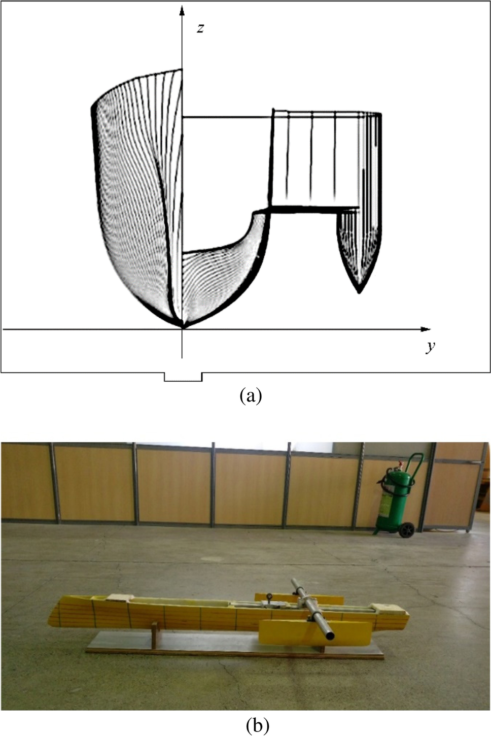 Figure 1 The body plan and the model of trimaran. a Body plan. b Model of trimaranTable 1 Main properties of the prototype trimaran and its scaled model
Specifications Full scale Model scale Length overall (m) 124.38 1.555 Length on waterline (m) 123.24 1.541 Length between perpendiculars (m) 120.10 1.501 Beam overall (m) 21.78 0.272 Beam on waterline (m) 9.612 0.121 Depth (m) 11.78 0.147 Draft (m) 4.38 0.055 Length of side hull (m) 36.00 0.450 Beam of the side hull (m) 2.362 0.030 Depth of the side hull (m) 8.136 0.102 Draft of the side hull (m) 2.72 0.034 Displacement (t) 2249 0.0044 2.2 Experimental Setup
The model tests were conducted in the National Iranian Marine Laboratory (NIMALA) towing tank facilities. It has a 400-m length, a 6-m width, and a 4-m depth. The towing carriage is a manned vehicle with the dimensions of 7 m × 7.6 m with two velocity ranges. Its low and top motor velocities are in the range of 0.5 to 5 m/s and 4.5 to 19 m/s, respectively. This towing tank, as the most efficient and largest country reference, was established in 2013 to carry out all design and engineering tests for surface ships and submarines. NIMALA joined in Towing Tank Conference (ITTC) in 2017. NIMALA towing tank facility is shown in Figure 2. The towing carriage included a dynamometer for resistance measurement and two potentiometers to record the bow and astern motions of the model during the tests. The dynamometer was connected to the model using a towing post with a heaving road and a hinged mechanism. Therefore, the model was designed so that it was free for heaving and pitch motions but constrained for surge, sway, roll, and yaw motions. Moreover, to minimize artificial trim effects, the towing post was connected to the model at the intersection of the propeller shaft line with the vertical centers of gravity.
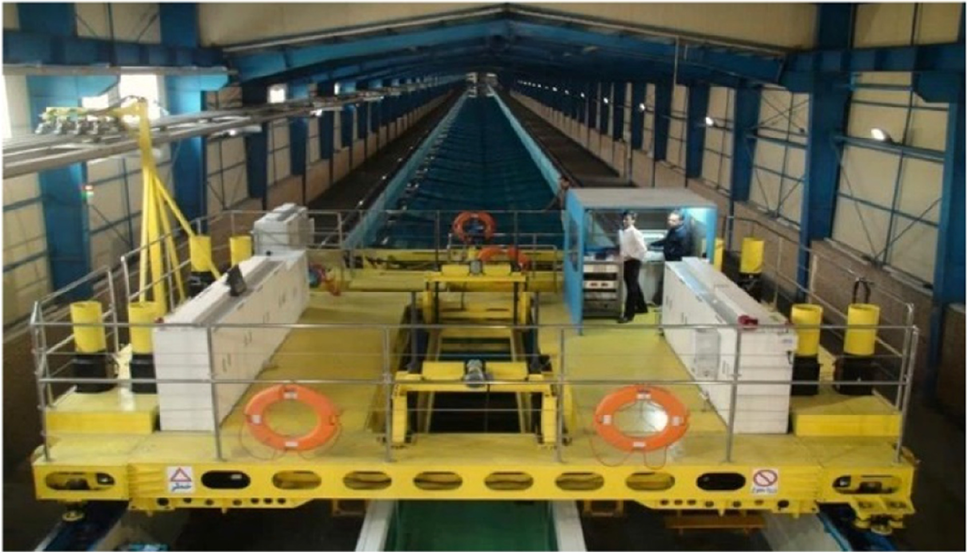 Figure 2 A view of NIMALA towing tank with a carriage. (a) Asymmetric inboard, (b) Asymmetric outboard, (c) Symmetrical
2.3 Test Configurations
In the present study, testing was carried out in two lateral (separation) positions and two longitudinal (stagger) positions of side hulls using both the symmetric and asymmetric forms. After completing the series of experiments with asymmetric outboard side hulls, two side hulls were reversed so that their flat side was placed outwards. The experiments were also repeated for asymmetric inboard side hulls. The definition of the longitudinal and lateral spacing between the main and the side hulls is shown in Figure 3. In this figure, the position of side hulls has been shown as separation ratio (S/L) and stagger ratio (R/L), where S is the distance between the main hull centerline and the side hulls centerline, R is the longitudinal positions of the side hulls transoms towards the main hull transom, and L is the length of the main hull at the waterline. For the same separation distance, three alternative side hull forms pose the same maximum overall beam and the same minimum tunnel width. Table 2 shows various configurations of the trimaran's lateral and longitudinal spacing.
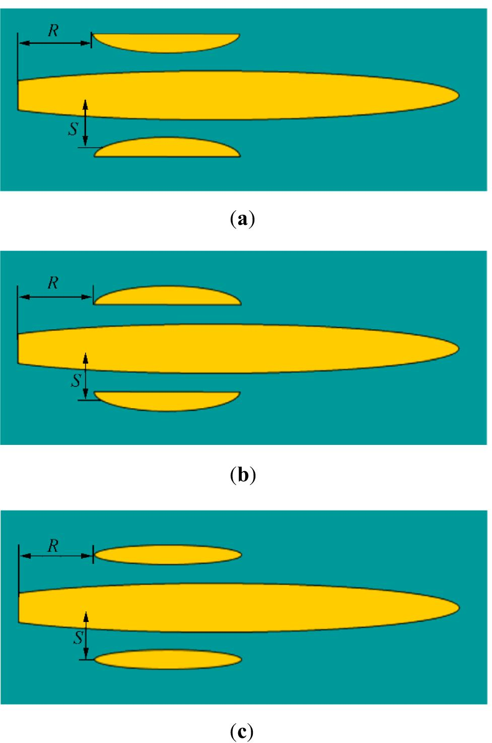 Figure 3 Stagger and separation definition. a Asymmetric inboard. b Asymmetric outboard. c SymmetricalTable 2 Various configurations of the trimaran's lateral and the longitudinal spacing
Configuration Stagger ratio (R/L) Separation ratio (S/L) Tri-1 0 0.14 Tri-2 0 0.16 Tri-3 0.15 0.14 Tri-4 0.15 0.16 Figure 4 shows the experimental setup and wave patterns of the model during the tests from the top view of the towing tank for three side hull forms, including inboard, outboard, and symmetric. During the model tests, the inboard and outboard type outriggers displayed significant wave spray in the stem. However, the shape of symmetry outrigger generated moderate stem wave spray.
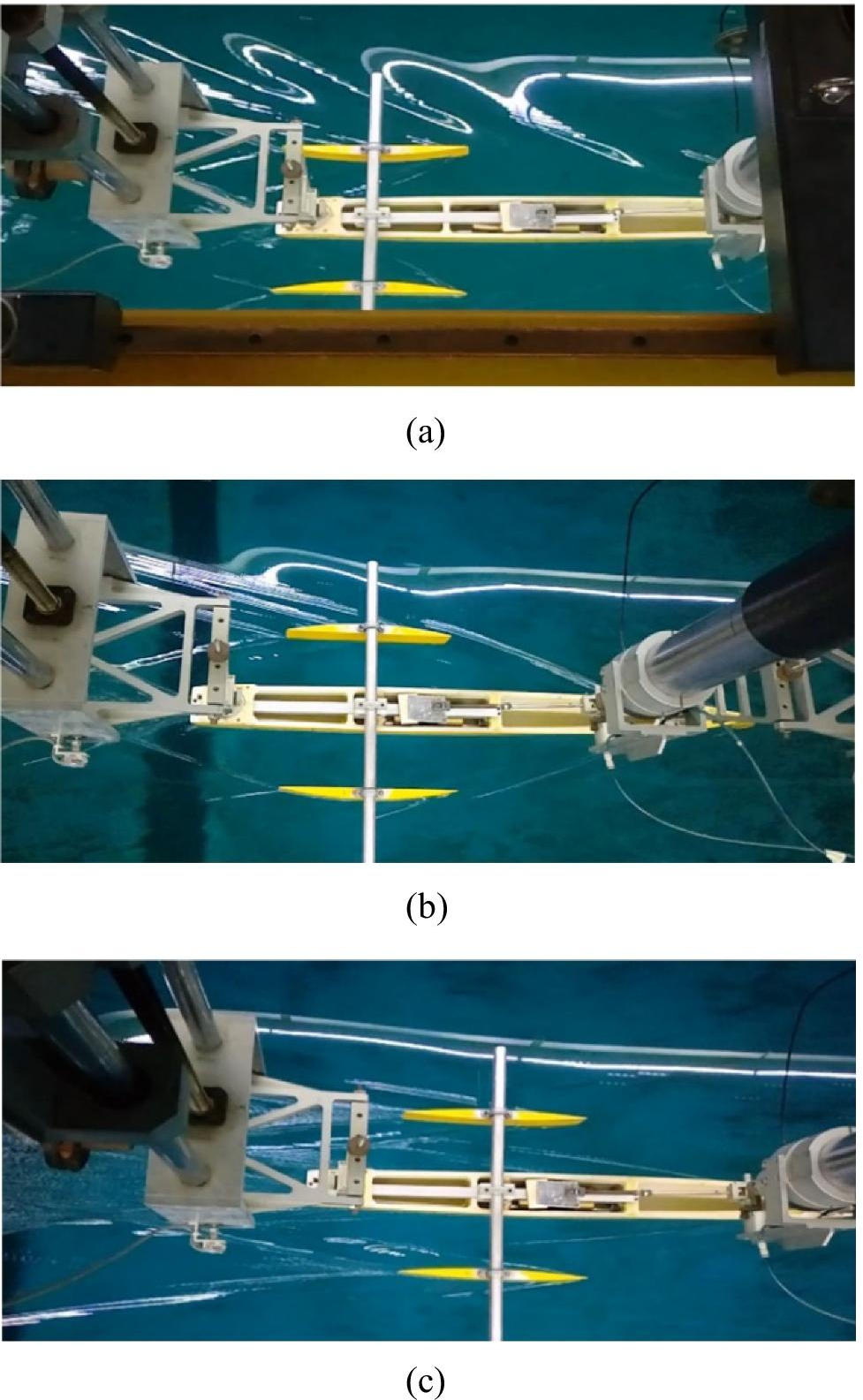 Figure 4 Snapshots of the trimaran model during the tests. a Inboard side hulls in the Tri-1configuration, b Outboard side hulls in the Tri-4 configuration, c Symmetric side hulls in the Tri-4configuration
3 Model Test Results
The model was experimentally tested at 6 velocities corresponding to ship velocities from 15 to 40 knots at 5 knots increments in terms of Froude numbers from 0.225 to 0.60. The theory of trimaran resistance can be found in Appendix 1. The relationship between the total resistance coefficient ($ {C}_{T} $) and the Froude number Fr for three different side hulls in various configurations is plotted in Figs. 5, 6, and 7. An inferred, in Tri-1 and Tri-2 configurations that side hulls have been aligned with the transom of the main hull (no stagger), $ {C}_{\mathrm{T}} $ has decreased with increasing Fr. However, in cases of Tri-3 and Tri-4 that side hulls have been located in front of the transom, $ {C}_{T} $ has not consistently changed with increasing the Froude number until $ Fr=0.5 $. From this Froude number on, $ {C}_{T} $ has slowly decreased. Also, as shown in these figures, the stagger positions of the side hulls have affected the total resistance of the model. At lower Froude numbers, by moving the outriggers toward the transom of the central hull, $ {C}_{T} $ is significantly reduced because of the wave cancelation effects. At higher Froude numbers, the effect of stagger position on $ {C}_{T} $ decreases. Our results demonstrated that separation variations had less effect on $ {C}_{T}. $
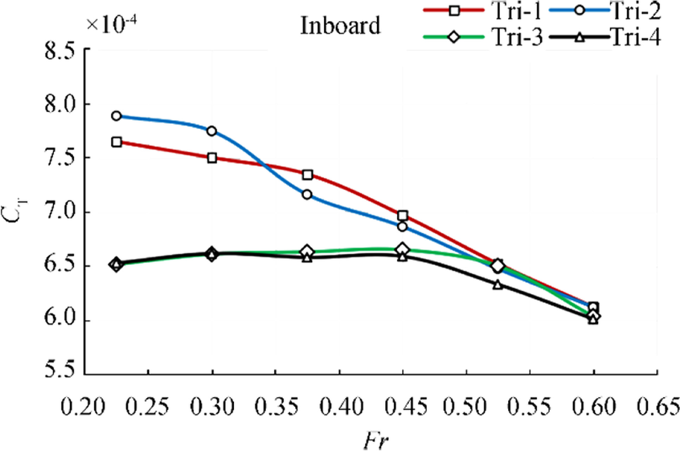 Figure 5 Relationship between $ {C}_{T} $ and Fr for asymmetric inboard side hulls
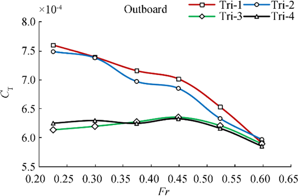 Figure 6 Relationship between $ {C}_{T} $ and Fr for symmetric outboard side hulls
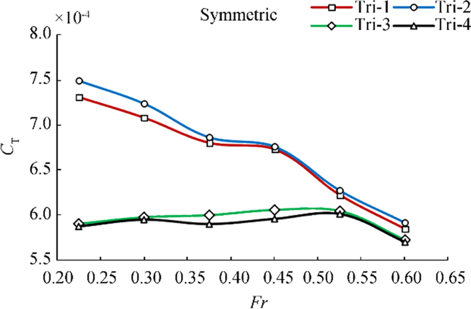 Figure 7 Relationship between $ {C}_{T} $ and Fr for symmetric side hulls
Regarding the trimaran configuration, the interference effect between the main and side hulls had a major influence on $ {C}_{T} $ so that the relative locations of side hulls (stagger/separation) significantly affected the interference effect between the main and side hulls. Among these positions, the influence of longitudinal positions (stagger) was more prominent. Additionally, when side hulls were in zero staggers, this influence was unfavorable, as the stagger increases, less interference resistance acts on the respective hulls, favorable interference is produced in the middle stagger position of side hulls, and the trimaran has the best resistance performance. Therefore, we supposed that the optimum position of outrigger is the place where the waves generated by the central hull and the outrigger cancel out each other.
Results also revealed that the all-side hulls form had the best performance in the case of Tri-4. Thus, it was concluded that various configurations show different flow patterns, and more importantly different total drag values. More specifically, in this study, the trend and value of total drag changed based on the Fr number and so the trimaran velocity. This suggested that any new modification in a trimaran should be applied considering the desired velocity. Furthermore, in the model trimaran, $ {C}_{T} $ rapidly decreased by increasing the Fr number, indicating the great effort on the trimaran modification at a higher velocity.
The flow pattern and the produced wave also depended on the side hull, whereas the side hull approached the main hull, and the affected area became more narrow and smaller. Conversely, the higher transversal distance caused the affected area to stretch to the aft of the trimaran; however, the wave interaction may reduce. Besides, moving the side hull toward the front part of the main hull caused the affected area to stretch toward the front of side while it narrowed and somewhat limited around and attached to the hull wall area.
The effect of side hulls symmetry on the trimaran's $ {C}_{T} $ is demonstrated in Figs. 8, 9, 10, and 11. As shown in Figure 8, the results of outboard and inboard side hulls, in the case of Tri-1, are almost similar in magnitude and physical trend. In this case, the symmetric side hull had the lowest $ {C}_{T} $ value and outperformed the other forms. In the Tri-2 configuration (shown in Figure 9), the inboard side hulls showed the weakest performance with higher magnitudes. In this case, the outboard and symmetric outriggers were relatively similar regarding the physical trend and magnitudes. Therefore, the model with symmetric side hulls performed slightly better than the outboard Tri-2 configuration.
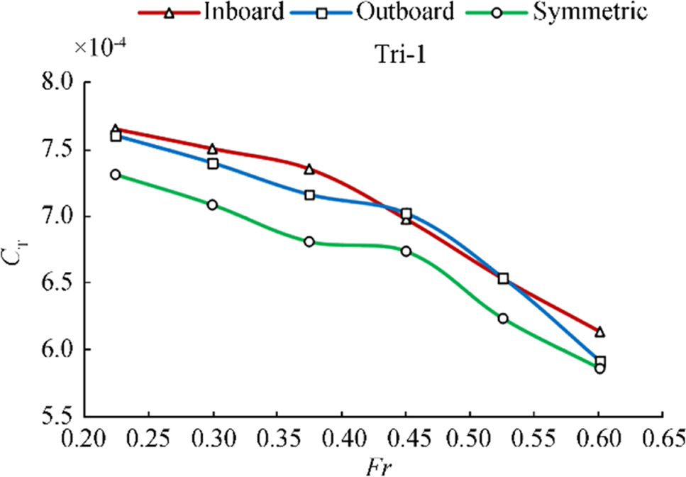 Figure 8 Comparison of $ {C}_{T} $ for three side hull forms in Tri-1 configuration
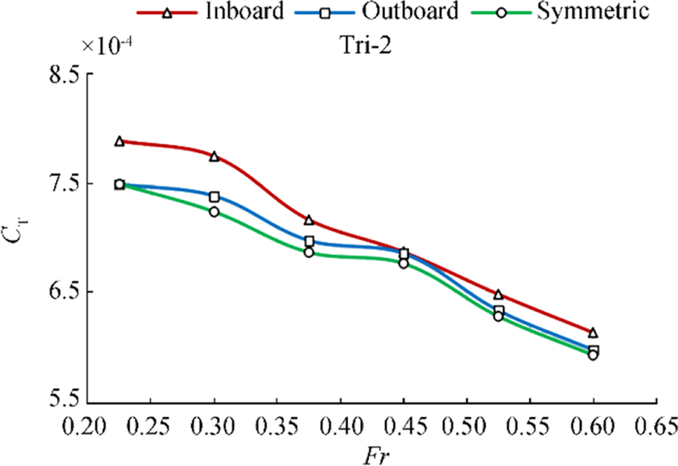 Figure 9 Comparison of $ {C}_{T} $ for three side hull forms in Tri-2 configuration
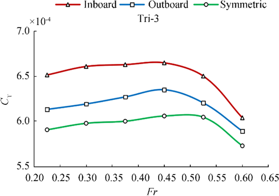 Figure 10 Comparison of $ {C}_{T} $ for three side hull forms in Tri-3 configuration
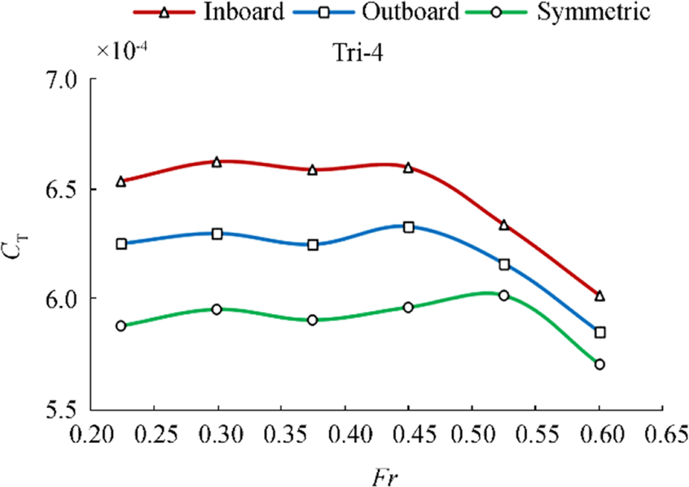 Figure 11 Comparison of $ {C}_{T} $ for three side hull forms in Tri-4 configuration
As shown in Figs. 10 and 11, we can see that the physical trends of experiment results are similar for all the three different side hulls in cases of Tri-3 and Tri-4. In these configurations, the symmetric side hulls had the best performance in terms of resistance among three kinds of outriggers. Furthermore, according to Figs. 10 and 11, the inboard form shows weak performance indicated by significantly high values throughout the considered Froude numbers.
The trimaran configuration interaction of the bow wave system of the central hull with that of outriggers has an important effect on interference resistance. Side hull symmetry had a significant impact on the interference drag. This is mostly caused by the interaction of the bow waves of the main and side hulls. The asymmetric inboard configuration also experienced exaggerated interference effects. This was the result of the prominent wave interaction with the main hull caused by the high degree of curvature along the inboard shoulder of each side hull. In addition, the asymmetric outboard configuration, which was flat along the entire inboard face of the side hull, produced a narrower range of interference drag, while the symmetric hulls produced a moderate range of interference drag closer to the asymmetric inboard configuration (Ackers et al., 1997).
In summary, the high degree of inner side curvature amplified the wave interaction between the main and side hulls, which, in turn, increased the interference drag. In reverse, when the inner side was flat along the entire face of the outrigger, the interference resistance was weakened. Therefore, we can certainty state that asymmetric outboard side hulls could produce the smallest interference drag, asymmetric inboard had the highest interference drag, and symmetric produced moderate interference drag. Despite having slightly higher interference drag in comparison with asymmetric outboard side hulls, the symmetric side hulls had the lowest total resistance. On this account, optimum side hulls for a trimaran might be selected based on a trade-off between symmetry and asymmetry outboard to minimize baseline resistance and interference drag, respectively.
Further to this, the towing carriage included three sensors on the model to determine the total resistance and bow and astern motions to calculating the dynamic trim angle (Figure 12). Comparison of dynamic trim angle for trimaran hull at various speeds is shown in Figs. 13, 14, 15, and 16. As shown in Figs. 13 and 14, the physical trend of plots is similar for all the three different side hulls in cases of Tri-1 and Tri-2. The dynamic trim angle (by the astern) was very small for low speeds; however, it increased with increasing the model speed up to the maximum values at the Fr = 0.45 and decreased again. As shown in Figs. 15 and 16, in Tri-3 and Tri-4 configurations, the maximum trim angle occurs at Fr = 0.525. In total, our results indicated that the trim angle affected the resistance performance of the trimaran model and the symmetric side hull with the lowest trim angle had the lowest resistance among the three side hull forms. The uncertainty analysis of the experimental results can be found in Appendix 2.
 Figure 12 Experimental setup of National Iranian Marine Laboratory (NIMALA) towing tank
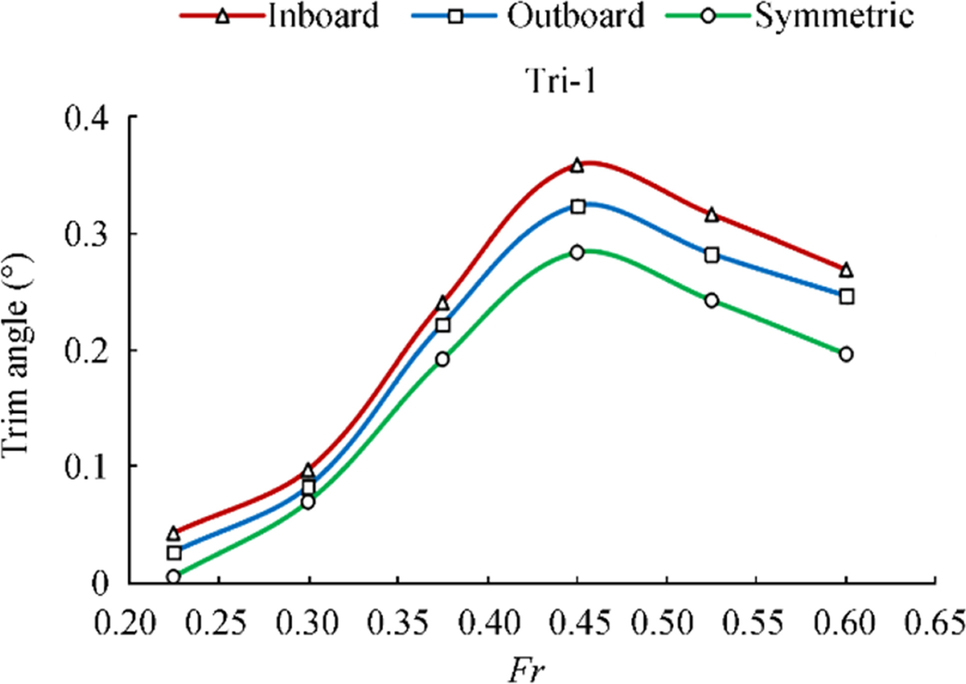 Figure 13 Comparison of trim angle for three side hull forms in Tri-1 configuration
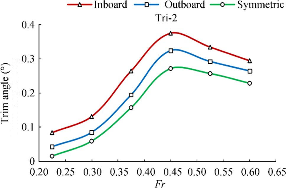 Figure 14 Comparison of trim angle for three side hull forms in Tri-2 configuration
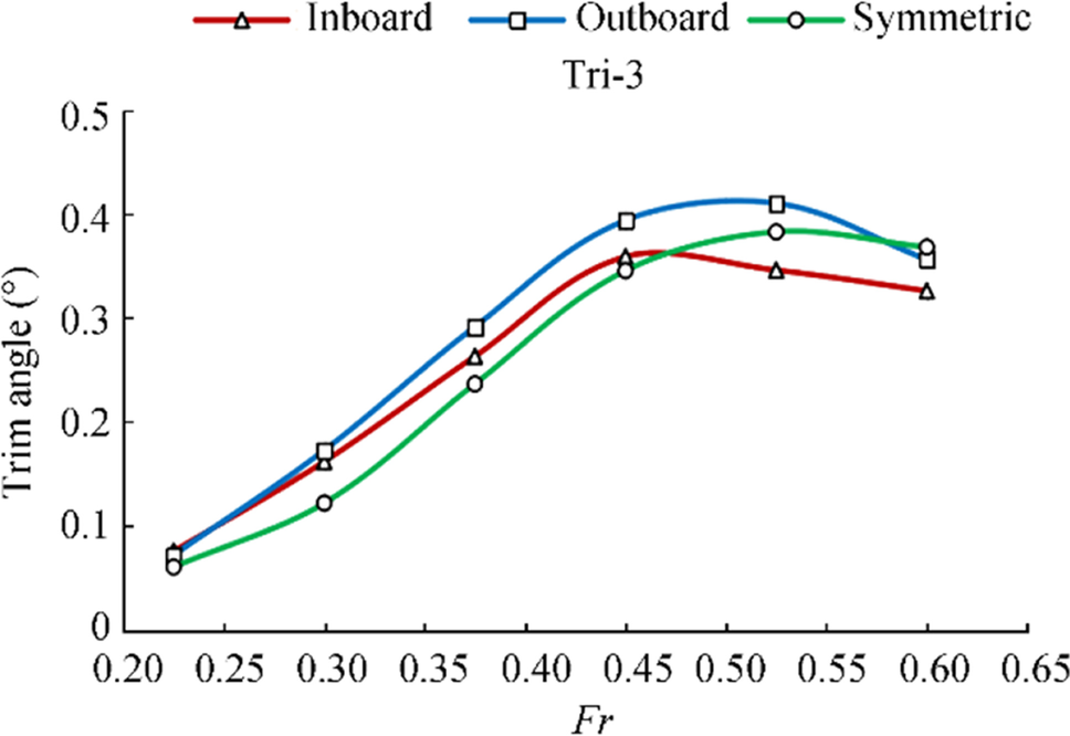 Figure 15 Comparison of trim angle for three side hull forms in Tri-3 configuration
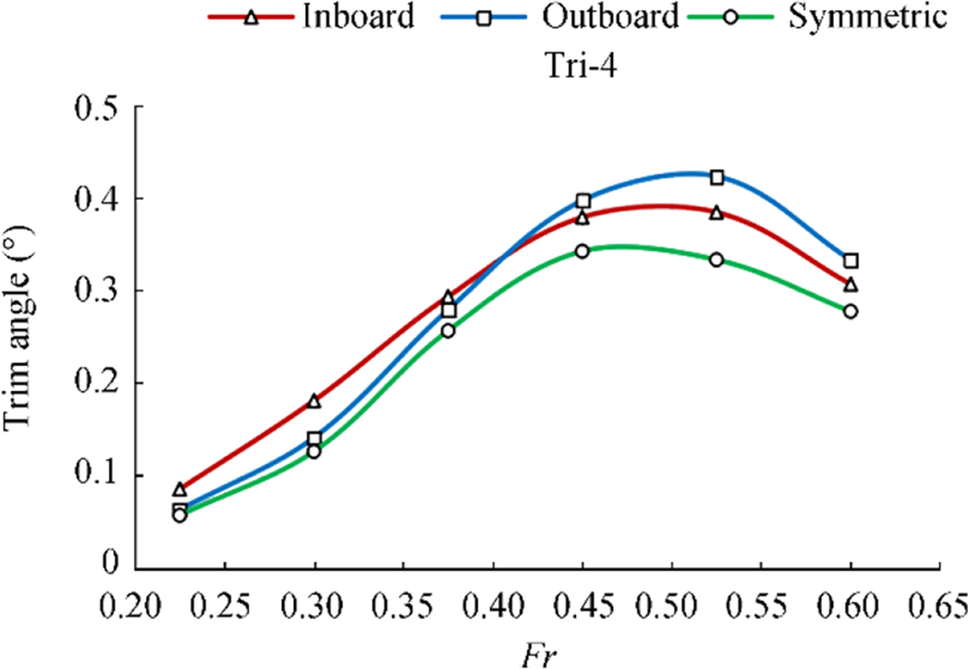 Figure 16 Comparison of trim angle for three side hull forms in Tri-4 configuration
4 Conclusion
The focus of this paper was on the influence of symmetry of the side hulls on the resistance performance of trimarans. Using a scale model of the trimaran, the model tests were carried out in the National Iranian Marine Laboratory (NIMALA) towing tank. Based on the results of the study, the following conclusions can be drawn:
1) In Tri-1 and Tri-2 configurations that side hulls are aligned with the transom of the main hull (no stagger), $ {\mathrm{C}}_{\mathrm{T}} $ decreases with increasing Fr. In cases of Tri-3 and Tri-4 that side hulls are located in front of the transom, CT does not consistently change with increasing the Froude number until $ Fr=0.5 $. After this Fr, CT slowly decreases.
2) The test results showed that the symmetry and stagger position of side hulls are the most important factors affecting CT of a trimaran.
3) The high degree of inner side curvature amplifies the wave interaction between the central and side hulls. Conversely, the inner side flat along the entire face of the outrigger weakens the wave interaction between the hulls. These results indicated that the highest interference drag appears in inboard followed by the symmetric, and the smallest appearing in the outboard side hull form. Despite having slightly higher interference drag in comparison with asymmetric outboard side hulls, the symmetric side hulls have the lowest total resistance. Therefore, optimum side hulls for a trimaran might be selected based on a trade-off between symmetry and asymmetry outboard to minimize baseline resistance and interference drag, respectively.
4) By moving the outriggers from stern stagger to mid and forward stagger, $ {C}_{T} $ is significantly reduced because of the better wave cancelation effects. Besides, the separation variations have less effect on $ {C}_{T} $.
5) It was concluded that various configurations show different flow patterns, and more importantly different total drag values. More specifically, the trend and value of total drag changes based on the Froude number Fr and trimaran velocity.
Appendix 1: Theory of trimaran resistance
The total calm water resistance coefficient of a monohull ship model can be written as:
$$ {C}_{TM}({R}_{e},{F}_{r})={\left(1+k\right)C}_{FM}({R}_{e})+{C}_{WM}({F}_{r}) $$ (1) Insel and Molland (1991) proposed the total calm water resistance coefficient of a catamaran as follows. This formula is also applicable for other multihulls:
$$ {C}_{T}^{\mathrm{M}\mathrm{o}\mathrm{d}\mathrm{e}\mathrm{l}}=(1+\beta k){C}_{F}^{\mathrm{i}\mathrm{s}\mathrm{o}\mathrm{l}..}+\tau {C}_{W}^{\mathrm{i}\mathrm{s}\mathrm{o}\mathrm{l}..} $$ (2) $ {C}_{T}^{\text{Model}} $ is the total resistance coefficient, $ {C}_{F}^{\text{isol}.} $ and $ {C}_{W}^{\text{isol}..} $ are the coefficient values of frictional and wave resistance in isolation, respectively. $ {C}_{F} $ is calculated by the ITTC-1957 method using the below equation:
$$ {C}_{F}=\frac{0.075}{{\left({\text{log}}_{10}\mathrm{ }{R}_{e}-2\right)}^{2}} $$ (3) The length of the main hull of a trimaran ship is normally different from that of the side hulls. This will result in a different $ {R}_{e} $ for the main and side hulls and different frictional resistance coefficients. Individual lengths of the main and the side hulls are used in deriving different $ {R}_{e} $ and the separate resistance coefficients. The total frictional resistance coefficient of a trimaran ship may be expressed as a function of the wetted surface area of each hull with respect to the total wetted surface area of all three hulls as follows:
$$ {C}_{F}^{\mathrm{i}\mathrm{s}\mathrm{o}\mathrm{l}..}={C}_{F}^{\mathrm{m}\mathrm{a}\mathrm{i}\mathrm{n}}\left(\frac{{S}^{\mathrm{m}\mathrm{a}\mathrm{i}\mathrm{n}}}{{S}^{\mathrm{m}\mathrm{a}\mathrm{i}\mathrm{n}}+2{S}^{\mathrm{s}\mathrm{i}\mathrm{d}\mathrm{e}}}\right)+{C}_{F}^{\mathrm{s}\mathrm{i}\mathrm{d}\mathrm{e}}\left(\frac{{2S}^{\mathrm{s}\mathrm{i}\mathrm{d}\mathrm{e}}}{{S}^{\mathrm{m}\mathrm{a}\mathrm{i}\mathrm{n}}+2{S}^{\mathrm{s}\mathrm{i}\mathrm{d}\mathrm{e}}}\right) $$ (4) And wave resistance coefficient as:
$$ {C}_{W}^{\mathrm{i}\mathrm{s}\mathrm{o}\mathrm{l}..}={C}_{W}^{\mathrm{m}\mathrm{a}\mathrm{i}\mathrm{n}}\left(\frac{{S}^{\mathrm{m}\mathrm{a}\mathrm{i}\mathrm{n}}}{{S}^{\mathrm{m}\mathrm{a}\mathrm{i}\mathrm{n}}+2{S}^{\mathrm{s}\mathrm{i}\mathrm{d}\mathrm{e}}}\right)+{C}_{W}^{\mathrm{s}\mathrm{i}\mathrm{d}\mathrm{e}}\left(\frac{{2S}^{\mathrm{s}\mathrm{i}\mathrm{d}\mathrm{e}}}{{S}^{\mathrm{m}\mathrm{a}\mathrm{i}\mathrm{n}}+2{S}^{\mathrm{s}\mathrm{i}\mathrm{d}\mathrm{e}}}\right) $$ (5) According to Hughes-Prohaska, $ (1+k) $ is the form factor that is assumed to be the same for both the monohull and multihull in isolation. $ \beta $ and $ \tau $ are the viscous and wave resistance interference factors, respectively. For practical purposes, the form factor is assumed constant over the velocity range and between the model and ship. Although for the first time, those interference factors were derived by Insel and Molland (1991) for a catamaran, they have formed reasonable approximations for other multihulls (Yanuar et al., 2015a, b). Molland et al. (2011) developed empirical formula for $ (1+k) $ for round bilge monohulls and $ (1+\beta k) $ for catamarans based on model test results:
$$ \left(1+k\right)=2.76{(L/{\nabla }^{1/3})}^{-0.4} $$ (6) $$ \left(1+\beta k\right)=3.03{(L/{\nabla }^{1/3})}^{-0.4} $$ (7) $ \tau $ is defined as:
$$ \tau =\frac{{C}_{W}^{\mathrm{M}\mathrm{o}\mathrm{d}\mathrm{e}\mathrm{l}}}{{C}_{W}^{\mathrm{i}\mathrm{s}\mathrm{o}\mathrm{l}..}}=\frac{{C}_{T}^{\mathrm{M}\mathrm{o}\mathrm{d}\mathrm{e}\mathrm{l}}-{(1+\beta k)C}_{F}^{\mathrm{i}\mathrm{s}\mathrm{o}\mathrm{l}..}}{{C}_{T}^{\mathrm{i}\mathrm{s}\mathrm{o}\mathrm{l}..}-{(1+k)C}_{F}^{\mathrm{i}\mathrm{s}\mathrm{o}\mathrm{l}..}} $$ (8) The following equations were applied to derive the $ {C}_{Ts} $ value for the ship.
$$ {C}_{Ts}={C}_{W}^{\mathrm{S}\mathrm{h}\mathrm{i}\mathrm{p}}+{(1+\beta k)C}_{FS}^{\mathrm{i}\mathrm{s}\mathrm{o}\mathrm{l}..} $$ (9) $$ {C}_{W}^{\mathrm{M}\mathrm{o}\mathrm{d}\mathrm{e}\mathrm{l}}={C}_{W}^{\mathrm{S}\mathrm{h}\mathrm{i}\mathrm{p}} $$ (10) $$ {C}_{Ts}={C}_{T}^{\mathrm{M}\mathrm{o}\mathrm{d}\mathrm{e}\mathrm{l}}-{\left(1+\beta k\right)C}_{F}^{\mathrm{i}\mathrm{s}\mathrm{o}\mathrm{l}..}+\left(1+\beta k\right){C}_{FS}^{\mathrm{i}\mathrm{s}\mathrm{o}\mathrm{l}..} $$ (11) $$ {C}_{Ts}={C}_{T}^{\mathrm{M}\mathrm{o}\mathrm{d}\mathrm{e}\mathrm{l}}-(1+\beta k){(C}_{Fm}^{\mathrm{i}\mathrm{s}\mathrm{o}\mathrm{l}..}-{C}_{Fs}^{\mathrm{i}\mathrm{s}\mathrm{o}\mathrm{l}..}) $$ (12) The residuary resistance coefficient CR of the tested model was derived by subtracting the frictional resistance from the total measured resistance. The frictional resistances for the central and the side hulls were firstly calculated individually using the "ITTC 1957 model-ship correlation line". Then, CR was in the below form:
$$ {C}_{R}=\frac{{R}_{T}-{R}_{FC}-{2R}_{FS}}{\frac{1}{2}\rho {V}^{2}({S}_{C}+{2S}_{S})}-{C}_{A} $$ (13) where $ {R}_{T} $ is the total resistance of the model, $ {R}_{FC} $ is the calculated frictional resistance for the central hull, $ {R}_{FS} $ is the calculated frictional resistance for each side hull, $ {S}_{C} $ is the wetted surface area of the central hull, $ {S}_{S} $ is the wetted surface area of a side hull, and $ {C}_{A} $ is the correlation factor equal to 0.0004 (Lewis 1988). For slender ship hulls, the form resistance is very small; so, the measured residuary resistance is dominated by the wave-making resistance.
It is also important to identify the components of the wave-making resistance of a trimaran ship. Firstly, the wave-making resistance calculations are separately carried out for the central and the side hulls. The resulted wave-making resistance coefficients $ {C}_{w0} $, excluding the wave interference between the hulls, is:
$$ {C}_{w0}=\frac{{R}_{WC}^{\mathrm{i}\mathrm{s}\mathrm{o}\mathrm{l}.}+{2R}_{WS}^{\mathrm{i}\mathrm{s}\mathrm{o}\mathrm{l}.}}{\frac{1}{2}\rho {V}^{2}({S}_{C}+{2S}_{S})} $$ (14) where $ {R}_{WC}^{\mathrm{i}\mathrm{s}\mathrm{o}\mathrm{l}.} $ is the wave-making resistance of the central hull alone, and $ {R}_{WS}^{\mathrm{i}\mathrm{s}\mathrm{o}\mathrm{l}.} $ is the wave-making resistance of a side hull alone. Then, the wave-making resistance coefficient $ {C}_{wi} $, due to the wave interaction effects of the three hulls will be:
$$ {C}_{wi}={C}_{w}-{C}_{w0} $$ (15) A positive $ {C}_{wi} $ represents added wave-making resistance due to the wave interference between the central and the side hulls. A negative $ {C}_{wi} $ means a reduction in total wave-making resistance due to wave cancelation effects between the hulls.
Appendix 2: The uncertainty analysis
For the results of the model experiments, an uncertainty analysis was carried out according to the 7.5–02-02–02 ITTC procedures and guidelines. The relative standard uncertainty components (wetted surface area and representative length of hull model) of resistance related to the hull geometry can be approximately estimated by the following equations, respectively (ITTC, 2014):
$$ {u}_{11}^{\text{'}}\left({R}_{T}\right)={u}^{\text{'}}(S)\frac{2}{3}\mathrm{ }{u}^{\text{'}}(\Delta ) $$ (16) $$ {u}_{12}^{\text{'}}\left({R}_{T}\right)=\frac{{C}_{F}}{{C}_{T}}.\mathrm{ }{\frac{0.87}{{\mathrm{l}\mathrm{o}\mathrm{g}}_{10}{R}_{e}-2}u}^{\text{'}}\left(L\right)\frac{{C}_{F}}{{C}_{T}}.\mathrm{ }{\frac{0.29}{{\mathrm{l}\mathrm{o}\mathrm{g}}_{10}{R}_{e}-2}u}^{\text{'}}\left(\Delta \right) $$ (17) Since the Reynolds number in a typical resistance test is on the order of 107, $ {u}_{12}^{\text{'}} $ is relatively negligible to $ {u}_{11}^{\text{'}} $. The combined standard uncertainty of resistance resulted from hull geometry can be estimated by Eq. (18) (ITTC, 2014):
$$ {u}_{1}^{\text{'}}\left(R\right)=\sqrt{{({u}_{11}^{\text{'}}\left({R}_{T}\right))}^{2}+{({u}_{12}^{\text{'}}\left({R}_{T}\right))}^{2}})\frac{2}{3}\mathrm{ }{u}^{\text{'}}(\Delta ) $$ (18) The uncertainty of carrier speed was also propagated into the resistance measurement as both dynamic pressure and Reynolds number (ITTC, 2014). These uncertainties were obtained as quantitatively by the following equations, respectively:
$$ {u}_{41}^{\text{'}}\left({R}_{T}\right)=2{u}^{\text{'}}(V) $$ (19) $$ {u}_{42}^{\text{'}}\left({R}_{T}\right)=\frac{{C}_{F}}{{C}_{T}}.\mathrm{ }{\frac{0.87}{{log}_{10}{R}_{e}-2}u}^{\text{'}}(V) $$ (20) where $ {u}_{42}^{\text{'}} $ is usually much less than $ {u}_{41}^{\text{'}} $ and negligible. Then, the combined standard uncertainty of resistance resulted from towing speed can be estimated as:
$$ {u}_{4}^{\text{'}}\left(R\right)=\sqrt{{({u}_{41}^{\text{'}}\left({R}_{T}\right))}^{2}+{({u}_{42}^{\text{'}}\left({R}_{T}\right))}^{2}})2\mathrm{ }{u}^{\text{'}}(V) $$ (21) Moreover, the relative uncertainty of water viscosity resulted from temperature can be estimated:
$$ {u}_{3}^{\text{'}}\left({R}_{T}\right)=\frac{{C}_{F}}{{C}_{T}}.\mathrm{ }{\frac{0.87}{{log}_{10}{R}_{e}-2}u}^{\text{'}}(\nu ) $$ (22) The uncertainty component of resistance resulted from calibration of dynamometer was also estimated by standard error estimation (SEE) (ITTC, 2014):
$$ {u}_{2}^{\text{'}}\left({R}_{T}\right)={u}^{\text{'}}\left({R}_{T}\right)=\mathrm{S}\mathrm{E}\mathrm{E} $$ (23) The standard uncertainty component from single test and repeat tests can be estimated by the following equations, respectively:
$$ {u}_{A}^{\text{'}}\left({R}_{T}\right)=\frac{Sdev}{{\widehat{R}}_{T}} $$ (24) $$ {u}_{A}^{\text{'}}\left({R}_{T}\right)=\frac{Sdev/{R}_{T}}{\sqrt{N}} $$ (25) Analyses of all significant uncertainty components related to the total resistance were combined to obtain the overall standard uncertainty by RSS method (ITTC, 2014):
$$ {u}_{C}^{\text{'}}\left({R}_{T}\right)=\sqrt{{({u}_{1}^{\text{'}})}^{2}+{({u}_{2}^{\text{'}})}^{2}{+({u}_{3}^{\text{'}})}^{2}+{({u}_{4}^{\text{'}})}^{2}{+({u}_{A}^{\text{'}})}^{2}} $$ (26) Also, the expanded standard uncertainty of the resistance with a confidence level (t) was estimated by Eq. (27) (ASME, 2005; ITTC, 2014):
$$ {U}_{p}={k}_{p}{u}_{c} $$ (27) An uncertainty analysis was finally carried out for results of symmetrical trimaran model in Tri-1 configuration. Figure 17 shows this analysis for carriage speed and total resistance coefficients. As shown, maximum uncertainty for this configuration of trimaran model occurs in $ {F}_{r} $=0.25 which is about 2.6%.
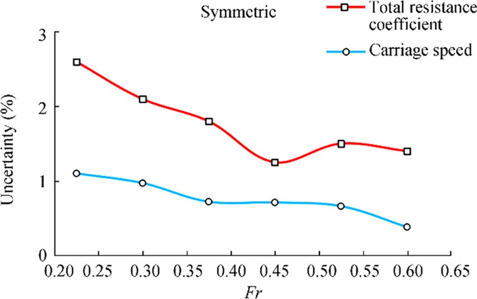 Figure 17 Uncertainties of experimental results for symmetrical trimaran model in Tri-1 configuration
 -
Figure 1 The body plan and the model of trimaran. a Body plan. b Model of trimaran
Figure 2 A view of NIMALA towing tank with a carriage. (a) Asymmetric inboard, (b) Asymmetric outboard, (c) Symmetrical
Figure 3 Stagger and separation definition. a Asymmetric inboard. b Asymmetric outboard. c Symmetrical
Figure 4 Snapshots of the trimaran model during the tests. a Inboard side hulls in the Tri-1configuration, b Outboard side hulls in the Tri-4 configuration, c Symmetric side hulls in the Tri-4configuration
Figure 5 Relationship between $ {C}_{T} $ and Fr for asymmetric inboard side hulls
Figure 6 Relationship between $ {C}_{T} $ and Fr for symmetric outboard side hulls
Figure 7 Relationship between $ {C}_{T} $ and Fr for symmetric side hulls
Figure 8 Comparison of $ {C}_{T} $ for three side hull forms in Tri-1 configuration
Figure 9 Comparison of $ {C}_{T} $ for three side hull forms in Tri-2 configuration
Figure 10 Comparison of $ {C}_{T} $ for three side hull forms in Tri-3 configuration
Figure 11 Comparison of $ {C}_{T} $ for three side hull forms in Tri-4 configuration
Figure 12 Experimental setup of National Iranian Marine Laboratory (NIMALA) towing tank
Figure 13 Comparison of trim angle for three side hull forms in Tri-1 configuration
Figure 14 Comparison of trim angle for three side hull forms in Tri-2 configuration
Figure 15 Comparison of trim angle for three side hull forms in Tri-3 configuration
Figure 16 Comparison of trim angle for three side hull forms in Tri-4 configuration
Figure 17 Uncertainties of experimental results for symmetrical trimaran model in Tri-1 configuration
Table 1 Main properties of the prototype trimaran and its scaled model
Specifications Full scale Model scale Length overall (m) 124.38 1.555 Length on waterline (m) 123.24 1.541 Length between perpendiculars (m) 120.10 1.501 Beam overall (m) 21.78 0.272 Beam on waterline (m) 9.612 0.121 Depth (m) 11.78 0.147 Draft (m) 4.38 0.055 Length of side hull (m) 36.00 0.450 Beam of the side hull (m) 2.362 0.030 Depth of the side hull (m) 8.136 0.102 Draft of the side hull (m) 2.72 0.034 Displacement (t) 2249 0.0044 Table 2 Various configurations of the trimaran's lateral and the longitudinal spacing
Configuration Stagger ratio (R/L) Separation ratio (S/L) Tri-1 0 0.14 Tri-2 0 0.16 Tri-3 0.15 0.14 Tri-4 0.15 0.16 -
Ackers BB, Thad JM, Tredennick OW, Landen CH, Miller EJ, Sodowsky JP, Hadler JB (1997) An investigation of the resistance characteristics of powered trimaran side-hull configurations. SNAME Transactions 105: 349–373 ASME (2005) Test uncertainty, The American society of mechanical engineers performance test code, American Society of Mechanical Engineers, No. PTC 19. 1–2005, New York Chen Y, Yang L, Xie Y, Yu S (2016) The research on characteristic parameters and resistance chart of operation and maintenance trimaran in the sea. Polish Maritime Research 23(s1): 20–24. https://doi.org/10.1515/pomr-2016-0041 Claire M, Andrea M (2014) Resistance analysis for a trimaran. International Journal of Mechanical, Aerospace, Industrial, Mechatronic and Manufacturing Engineering 8(1): 7–15 Deng R, Li C, Huang D, Zhou G (2015) The effect of trimming and sinkage on the trimaran resistance calculation. Procedia Engineering 126: 327–331. https://doi.org/10.1016/j.proeng.2015.11.199 Doctors L, Scrace R (2003) The optimization of trimaran side hull position for minimum resistance. Seventh International Conference on Fast Transportation (FAST 2003), Ischia, Italy, 1–12 Du L, Hefazi H, Sahoo P (2019) Rapid resistance estimation method of non-Wigley trimarans. Ships and Offshore Structures 14(8): 910–920. https://doi.org/10.1080/17445302.2019.1588499 Ghadimi P, Nazemian A, Ghadimi A (2019) Numerical scrutiny of the influence of side hulls arrangement on the motion of a Trimaran vessel in regular waves through CFD analysis. Journal of the Brazilian Society of Mechanical Sciences and Engineering 41(1): 1–10. https://doi.org/10.1007/s40430-018-1505-x Hafez K, El-Kot A-R (2011) Comparative analysis of the separation variation influence on the hydrodynamic performance of a high speed trimaran. Journal of Marine Science and Application 10(4): 377–393. https://doi.org/10.1007/s11804-011-1083-0 Hafez KA, El-Kot AA (2012) Comparative investigation of the stagger variation influence on the hydrodynamic interference of high speed trimaran. Alexandria Engineering Journal 51(3): 153–169. https://doi.org/10.1016/j.aej.2012.02.002 Hashimoto H, Amano S, Umeda N, Matsuda A (2011) Influence of side-hull positions on dynamic behaviors of a trimaran running in following and stern quartering seas. Proceedings of the 21th International Conference on Offshore and Polar Engineering, 573–580 Insel M, Molland AF (1991) An investigation into the resistance components of high speed displacement catamarans. Transactions of the Royal Institution of Naval Architects 134: 1–20. https://doi.org/10.1007/s11804-013-1193-y ITTC (2014) Testing and extrapolation methods in resistance towing tank tests, Recommended Procedures, 7.5–02–02–01 Iqbal M, Utama IKAP (2014) An investigation into the effect of water depth on the resistance components of trimaran configuration. Proceedings of the 9th International Conference on Marine Technology, Surabaya Lewis EV (1988) Principles of Naval Architecture. The Society of Naval Architects and Marine Engineers III: 323–324 https://ocw.mit.edu/courses/mechanical-engineering/2-700-principles-of-naval-architecture-fall-2014/ Luhulima RB, Utama I, Sulisetyono A (2016) Experimental investigation into the resistance components of displacement trimaran at various lateral spacing. International Journal of Engineering Research & Science (IJOER) 2: 21–29 Luhulima RB (2017) An Investigation into the resistance of displacement trimaran: a comparative analysis between experimental and CFD approaches. International Journal of Mechanical Engineering (IJME) 6: 9–18 Molland AF, Turnock SR, Hudson DA (2011) Ship resistance and propulsion: practical estimation of ship propulsive power. Cambridge University Press, 544. Verna S, Khan K, Praveen PC (2012) Trimaran hull form optimization, using ship flow. International Journal of Innovative Research and Development 1(10): 5–15 Yanuar Y, Gunawan G, Talahatu MA, Indrawati RT, Jamaluddin A (2013) Resistance analysis of unsymmetrical trimaran model with outboard side hulls configuration. Journal of Marine Science and Application 12(3): 293–297 https://doi.org/10.1007/s11804-013-1193-y Yanuar Y, Gunawan G, Talahatu MA, Indrawati RT, Jamaluddin A (2015a) Resistance reduction on trimaran ship model by biopolymer of eel slime. Journal of Naval Architecture and Marine Engineering 12(2): 95–102. https://doi.org/10.3329/jname.v12i2.19549 Yanuar Y, Gunawan G, Waskito KT, Jamaluddin A (2015b) Experimental study resistances of asymmetrical Pentamaran model with separation and staggered hull variation of inner side-hulls. International Journal of Fluid Mechanics Research 42(1): 82–94. https://doi.org/10.1615/interjfluidmechres.v42.i1.60 Zhang WP, Zong Z, Wang WH (2012) Special problems and solutions for numerical prediction on longitudinal motion of trimaran. Applied Mechanics and Materials 152-154: 1262–75. https://doi.org/10.4028/www.scientific.net/amm.152-154.1262 Zhang L, Zhang JN, Shang YC (2019) A potential flow theory and boundary layer theory based hybrid method for waterjet propulsion. Journal of Marine Science and Engineering 7(4): 113–132. https://doi.org/10.3390/jmse7040113