Experimental Investigation of a Hydraulic Turbine for Hydrokinetic Power Generation in Irrigation/Rainfall Channels
https://doi.org/10.1007/s11804-020-00152-4
-
Abstract
The development of microchannels with open flow for use in irrigation and rainy areas is challenged by electricity generation via hydrokinetic devices in shallow and low velocity flows. Conventional hydrokinetic turbines are known to be highly dependent on current speed and water depth. Another drawback of conventional turbines is their low efficiency. These shortcomings lead to the need to accelerate the flow in the channel system to enhance the extracted power. The method of deploying a novel turbine configuration in irrigation channels can help overcome the low performance of conventional hydrokinetic turbines. Therefore, this study experimentally presents a bidirectional diffuser-augmented channel that includes dual cross flow/Banki turbines. Results show that the maximum efficiency of the overall system with two turbines is nearly 55.7%. The efficiency is low relative to that of hydraulic turbines. Nevertheless, the result can be considered satisfactory given the low head of the present system. The use of this system will contribute to a highly efficient utilization of flows in rivers and channels for electrical energy generation in rural areas.Article Highlights• A bidirectional diffuser-augmented channel that includes dual cross flow/Banki turbines has been experimentally presented• Deploying a novel turbine configuration in irrigation channels can help overcome the low performance of conventional hydrokinetic turbines• This system promises more sufficient performance and higher efficiency than the conventional hydrokinetic turbines -
1 Introduction
The run-of-river scheme is generally adopted by micro-hydropower stations for the generation of electrical energy. This scheme utilizes the flow of water within the natural range of a river or channel. The scheme is not deployed with any type of reservoir. This application attracts investments in the electrification of hilly and isolated areas due to its easy construction, low cost, and use of small hydrological areas (Elbatran et al. 2015a; Rojanamon et al. 2009). Another micro-hydropower technology is stream or hydrokinetic technology in which tidal current turbines are installed in rivers or channels to generate renewable energy, which can then be optimized without the need for facilities such as weirs, reservoirs, and falls (Elbatran et al. 2015a; Vermaak et al. 2014).
This technology is basically similar to the run-of-river and tidal current schemes. Hydrokinetic technology can be utilized in rivers, channels, and shallow waters (Okot 2013). Hence, the technology of energy generation from present irrigation or rainy channels is classified as a run-of-river or hydrokinetic application. It is also a new type of micro-hydropower scheme that can help overcome the operational and economic problems of rural electrification for many developing and poor countries (Elbatran et al. 2015b).
1.1 Literature Survey
Countries that are surrounded by irrigation or rainfall channels have the opportunity to exploit this feature of nature. Adhau et al. (2012), Butera and Balestra (2015), and Zema et al. (2016) studied the technical and economic analysis of irrigation sites and networks. They concluded that irrigation projects for power generation are viable economically and technically. However, rainy regions have not received enough attention in the study of renewable power extraction. Tidal current "hydrokinetic" energy that can be captured from water flow in irrigation and rainfall channels can be a promising technology in countries with vast amounts of tidal current energy.
This section presents a review and discussion of important studies related to open channel flow, including the determination of the amount of harnessed power from channels and how to accelerate the flow through these channels. It also presents a detailed historical review and discussion around the performance characteristics of cross flow turbines (CFTs) or "Banki" turbines under the effects of geometrical and physical parameters.
1.1.1 Open Channel Flow
The Betz limit (Vennell 2013) sets the maximum actual available power to represent 16/27 or 59% of the maximum upstream hydrokinetic energy flux through an area equal to the cross-sectional area of a turbine. This formula assumes the absence of a confining wall in the flow. This assumption is satisfactory in the case of open seas, but it is not dependable in the case of channels (Goude and Ågren 2014). The general case utilizing a channel of arbitrary width was studied by Garrett and Cummins (2007). According to their estimations, the maximum extractable power in a channel can be calculated by the following equation:
$$ {P}_c=\frac{8}{27}{\left(1-{\rm{ \mathsf{ ɛ} }} \right)}^{-2}{\rm{ \mathsf{ ρ} }} A{U_o}^3 $$ (1) In this equation, ɛ represents the blockage ratio, which is defined as:
$$ {\rm{ \mathsf{ ɛ} }} =\frac{A}{A_c} $$ (2) where Ac is the area of the channel cross-section.
The extra "efficiency" of (1 − ɛ)−2 relative to the Betz limit for a turbine is due to the influence of the confining wall boundary of the channel that may greatly increase the probable pressure drop. According to this formula, the amount of energy that can be captured by a turbine in a water channel has no theoretical limit.
High blockage ratios in channels that exceed the Betz limit are not the only important factor. A number of compromises and modifications are required for turbine design to exceed the Betz limit (Vennell 2013). Hence, Vennell (2012a, b, 2013) exceeded the Betz limit by utilizing the turbine farms in channels. This approach can maximize the power produced by each turbine and the total farm power. However, turbine farms in microscale channels as in the current study are not the perfect solution to overcome low turbine efficiency and exceed the Betz limit. This restriction is due to the low dimensions and free surface of these channels; in this case, these channels need long upstream and downstream distances to diminish the effect of flow disturbances. Hence, the current study utilized a unique type of dual turbines with special configuration for a ducted design to increase the total output power and thereby enhance system efficiency and exceed the Betz limit.
Bryden and Melville (2004), Bryden and Scott (2007), Vennell (2011), and Draper et al. (2014) paid close attention to the measurement of the amount of extractable flowing power in open channels. They estimated the potential power in channels by using various detailed analytical and numerical methods.
Arkel et al. (2011) presented a new type of kinetic hydropower turbine with an elongated vertical axis; the turbine is deployed to relatively small shallow water and channels. Goude and Ågren (2014) investigated numerically a vertical axis turbine in a channel. In their research, the turbine efficiency in the channel was higher than the turbine efficiency in a free flow case, and the maximum efficiency was obtained at a high tip speed ratio (TSR).
The free stream flow configuration normally requires a low pressure and high flow rate to harness energy, but conventional hydrokinetic turbines are most suitable for high mass flow and pressure (Kim et al. 2012). Hence, many studies tried to develop unique and new technology designs and systems to extract as much hydrokinetic energy as possible. For example, Shabara et al. (2015a, b), and Elbatran et al. (2015c) studied the channel flow properties of helical and vortex pool systems from the hydraulic perspective to increase the efficiency of energy conversion through channels.
Using ducted diffuser nozzles is the most efficient method to enhance velocity and create a low pressure region at the downstream, and it can thus increase the pressure drop and enhance power (Elbatran et al. 2016). Accelerated nozzles in channels, a subject in the renewable energy field that has received little attention, are the most efficient choice to accelerate flow and increase the harnessed power of flowing water. The most important advantage of utilizing nozzles is that turbine efficiency can exceed the Betz limit because the inlet turbine kinetic power available for this case rises due to the increase in flow velocity.
By focusing on only one parameter, that is, the inlet angle of the convergence nozzle, Khan et al. (2013) studied flow patterns on the basis of velocity and pressure behavior contours. Elbatran et al. (2015d, 2017) investigated numerically the effects of nozzle geometrical parameters, such as diameter ratio, nozzle configuration, nozzle edge shape, and convergence–divergence configuration, on the flow characteristics and Savonius turbine performance in small and microscale channels.
1.1.2 Performance and Operation of Banki/CFTs
The main cornerstone of the development of open channel flows is the appropriate turbine system that can be utilized in channels. Various conventional current energy turbines, such as horizontal axial flow turbines and vertical axis flow turbines, can be used to capture hydrokinetic energy from water flow. One of the most attractive and unique turbines is the CFTs, which is also known as the Banki and Ossberger turbine. This turbine is practical, easy to construct, and cost-effective (Olgun 1998).
The CFTs is originally a hydropower turbine, but it is most appropriate for run-of-river applications due to its low requirement for large head and its dependence on flow rate relative to the other types of hydroturbines (Walseth 2009). The main advantage of this turbine is its ability to keep maximum efficiency with different flow ranges (Walseth 2009). Hence, it is a good option to be deployed in current channels.
The performance of CFTs depends on geometrical parameters such as runner diameter ratio, nozzle entry arc, guide vanes, number of blades, angle of attack, and inlet and outlet blade angles.
The work of Mockmore and Merryfield (1949) is one of the oldest and most important studies on CFTs; in this study, they defined the hydraulic efficiency of these turbines and the relation between the angle of attack (α) and the inlet blade angle (β), suggested a value of 16° for the angle of attack, and obtained a maximum efficiency of 68%. Nakase et al. (1982) studied the effects of nozzle shape on the performance of CFTs. Khosrowpanah et al. (1988) studied experimentally the performance of CFTs through different geometrical parameters under various flow and head conditions. Their results indicated that the maximum efficiency of CFTs increases as the nozzle entry arc increases or as the runner aspect ratio decreases. In their work, the optimum number of blades, diameter ratio, and angle of attack were 15, 0.68, and 16°, respectively. Furthermore, the peak value of efficiency occurred at a speed ratio of 0.52. Fiuzat and Akerkar (1991) proved that a turbine's second stage contributes significantly to power production relative to that reported in the analytic literature. Desai and Aziz (1994) concluded that the maximum efficiency of CFTs decreases with an increase in the angle of attack in the range of 22°–32° and increases when the number of blades increases from 15 to 30, the optimum diameter ratio is in the range of 0.6–0.75, and the optimum exit angle is 55°. The peak value of efficiency is almost 88% at a speed ratio of approximately 0.55. Totapally et al. (1994) reported that CFTs are most efficient when nozzles are narrower than the runner, the angle of attack ranges from 22° to 24°, the number of blades is 35, and the exit angle is smaller than 90°. Olgun (1998) obtained the highest efficiency of 72% at a runner diameter ratio of 0.67 and blade inlet and outlet angles of 30° and 90°. Kokubu et al. (2013) proved that CFT efficiency improves in the presence of a guide vane with a current plate. Kaunda et al. (2014a) showed experimentally the highest turbine efficiency of 79%.
Researchers have recently focused on the use of computation fluid dynamics (CFD) in investigating and designing CFTs. Choi et al. (2008) investigated the effects of turbine configuration on CFTs' performance and internal flow properties by using CFD analysis. They achieved the maximum efficiency given a 25° angle of attack, 87° blade exit angle, and 26 blades; the efficiency also increased with a narrow nozzle passage. Andrade et al. (2011) used ANSYS CFX and proved numerically that 68.5% of energy transfer occurs in the first stage and that the remaining 31.5% of energy transfer occurs in the second stage. Sammartano et al. (2013) used CFD simulations to design the main geometrical parameters of CFTs. They achieved a high efficiency of 86% for a turbine with 35 blades and an attack angle of 22°. Kaunda et al. (2014b) studied numerically the flow profile in a CFT at different operating conditions by using ANSYS CFX to calculate the turbine performance.
CFTs are most appropriate for run-of-river and wave generation applications because unlike other types of hydropower turbines, their efficiency mainly depends on flow rate. Choi et al. (2009, 2010), and Prasad et al. (2014) studied experimentally and numerically the performance of CFTs as direct drive turbines for wave power generation and reported the highest efficiencies of 51.7%, 51.6%, and 55%, respectively. Kim et al. (2015) recently integrated CFTs in a power takeoff (PTO) system of a new floating wave energy converter. Kim et al. (2012) proposed a new configuration of CFTs for harnessing tidal energy by utilizing a large channel area. Elbatran et al. (2015e, 2018) proposed numerically the current zero-head CFTs to extract tidal current "hydrokinetic" power in microscale channels. CFTs are indeed suitable for other applications, such as tidal, tidal current, and wave power generation, in addition to hydropower applications.
Extensive research has used the recommended geometrical parameters for hydropower applications despite the differences in their configurations and arrangements. However, these parameters do not accurately signify optimum parameters, especially the inlet and outlet angles of runner blades. The theoretical understanding of changing these angles so as to make them suitable for hydrokinetic applications, as discussed in [46], is limited. Hence, the current study continues the numerical work of Elbatran et al. (2015e) with an experimental study and with the optimum inlet and outlet angles of turbines determined in Elbatran et al. (2018). The outcome of the literature review motivates the objectives of the current study, as shown in the following section.
1.2 Problem Statement, Scope, and Objectives of the Study
Irrigation or rainy channels show great potential in the development of the renewable energy sector in developing countries. However, this scheme has yet to be fully discovered as researchers are still searching for solutions to the low velocity and low depth of current in open flow microchannels. The problem of low current is the main consideration of this study. This issue has become important because conventional tidal current turbines are known to be highly dependent on current speed and water depth. Moreover, conventional tidal current turbines have low efficiency.
These shortcomings highlight the need to accelerate the flow in the channel system to increase the amount of harnessed power. The deployment of a novel turbine configuration in channels is a solution to overcome the low efficiency of conventional hydrokinetic turbines. Therefore, the main goal of this research is to improve the flow characteristics and enhance the overall efficiency of the system so as to effectively extract tidal current energy from flows in a channel, stream, or river. A new configuration system with bidirectional nozzles, along with an optimized runner design of cross flow upper and lower turbines, based on the results of Elbatran et al. (2015e, 2018) is developed for use in microchannels. Experimental studies are performed to investigate the flow field characteristics and turbine performance through the nozzle system and to evaluate the final prototype's efficiency.
2 Prototype Model
Countries such as Malaysia have a large number of irrigation and/or rainy channels that could be maximized. However, the dependence on these irrigation channels has not been widely considered in the field of renewable energy. Moreover, many developing countries lack the sites required for generating potential energy. The development of open flow microchannels that suit Malaysian irrigation and rainy channels suffers from major problems such as low velocity of current and low performance of conventional tidal current turbines. The low current characteristics of these channels call for modifications of channel design. Using accelerated nozzle and Banki turbines is the most effective solution to overcome these problems.
A model of an augmented diffuser channel comprising twin CFTs (Figure 1) is installed in a micro water channel. In this configuration, the nozzle for incoming water has a free surface of 0.4 m. The upper intake occupies 0.15 m of the inlet water level while water enters the lower part of the inlet nozzle at 0.25 m water because the lower turbine is in normal mode and is thus expected to achieve high performance. Hence, the inlet nozzle is not necessarily symmetrical.
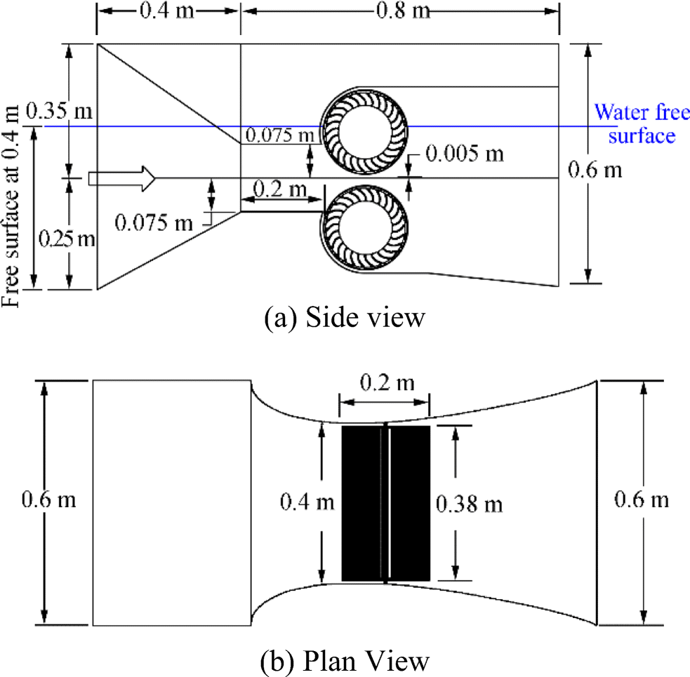 Figure 1 Schematics of augmented diffuser configuration, including cross flow turbine runners
Figure 2 shows the runner with a length, L, of 0.38 m, outer diameter of Do = 0.2 m, and inner diameter of Di = 0.1368 m; the diameter ratio is around 0.67, which is deemed applicable to ensure the runner's efficiency (Shimokawa et al. 2012). A total of 26 blades (Kim et al. 2012) are formed with an arc camber with a 2.7-mm thickness (t). Each blade's inlet and outlet angles are positioned at 105° and 45°, respectively, as configured in Elbatran et al. (2018) to be able to produce the best results, that is, increasing the exposed area of the blades to the incoming flow of water so as to consequently increase the torque, power, and efficiency. The clearance between the blade tip and the casing is set to 5 mm. The inlet velocity is based on the characteristics of Malaysian water channels, which have a low speed current of less than 1.0 m/s.
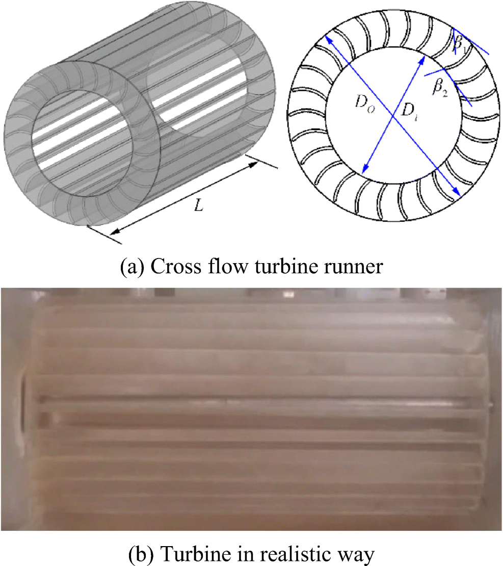 Figure 2 Final design of CFT runner
The free surface at the special system inlet enables the deployment of current arrangement in shallow water or at the surface of river applications and channels. The inlet nozzle is not necessarily symmetrical because one of the main purposes of the current study is to investigate the upper turbine's efficiency under the free surface effect. The lower turbine is in a normal mode of operation; thus, the preferable setup is to have the lower region occupy more area of water than the upper part to fully exploit the system and achieve high performance.
3 Characteristics of Flow Through the Current Hydrokinetic System
The system herein exploits the nature of CFTs, which absorb kinetic energy from high-velocity water flow. The efficiency of the system can be enhanced by bidirectional nozzles and diffusers to produce power. Thus, the dependence on potential energy is small due to the nature of the flow in irrigation and/or rainy channels. The energy generated by the new system is mainly gained from kinetic energy, pressure drop, and potential difference (small) due to the special design of the system. Therefore, the amount of obtainable power and the efficiency of the current CFTs is lower than those in other hydropower applications. Nevertheless, this configuration presents adequate and high efficiency relative to conventional tidal current systems and is suitable for use in areas with low potential energy, such as rural and remote areas.
The flow in a CFT is divided in two stages, as shown in Figure 3a. The flow of water is directed by the blades in the first stage. The flow then passes through the vaneless zone inside the runner and departs through the blades again in the second stage. Hence, the main advantage of a CFT is that flow passes through the turbine's runner twice, thus allowing the system to produce much power. The present CFT configuration is implemented without the need for a special casing, nozzle entry arc, and guide vanes. Hence, the flow of water enters the runner blades horizontally with a small angle of attack (α). This angle changes on the basis of the inlet angles of the runners. The entrained high-velocity flow of water between the turbine blade tips and the casing can produce jet flow, which contributes to energy generation by the two main power stages.
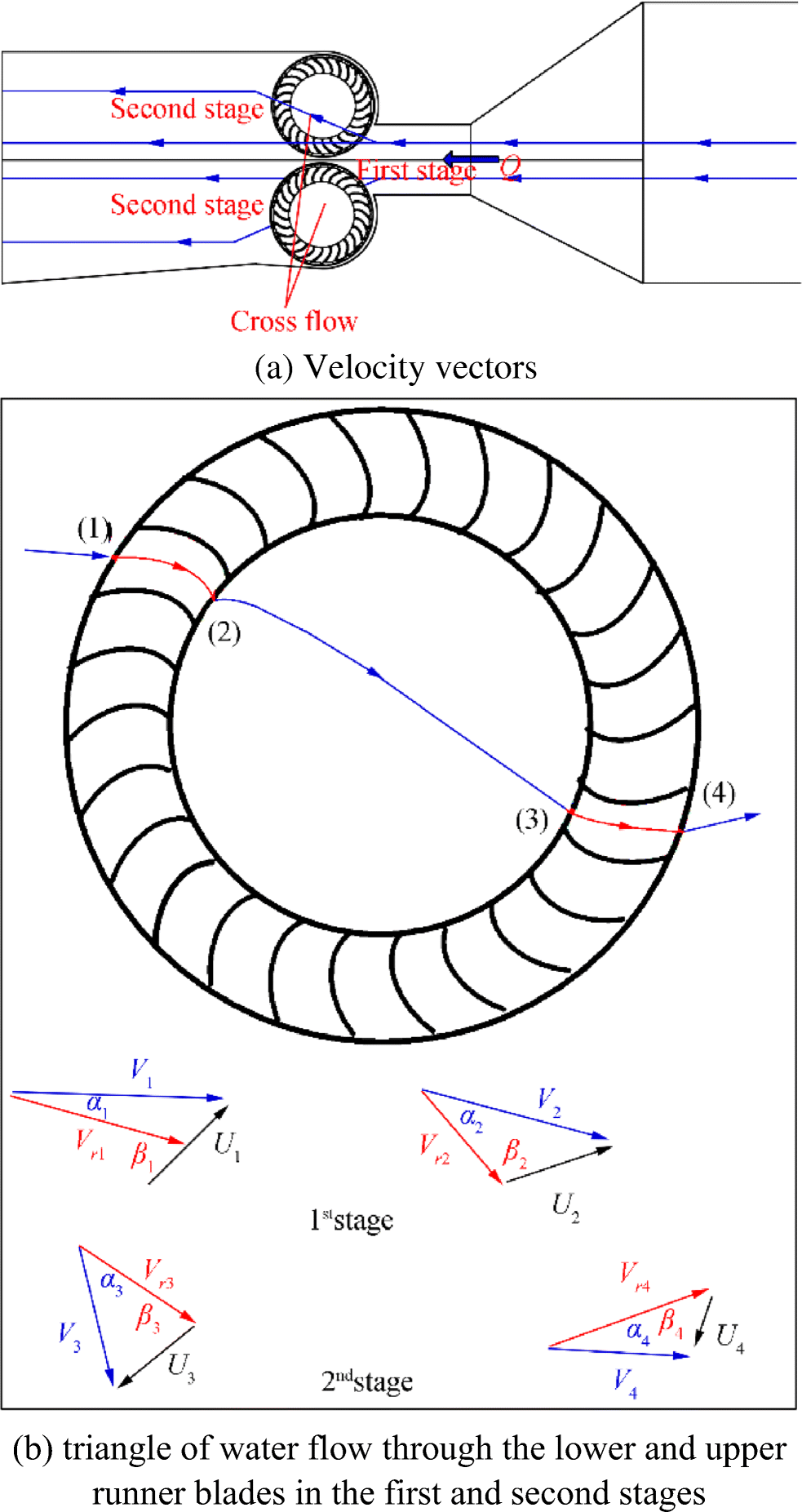 Figure 3 Flow directions and velocity triangles of the two stages through the turbines
The flow also departs the runner horizontally because the system has no head through the turbine runner. The inlet and outlet angles play a significant role in flow direction by enhancing the efficiency of the first stage and increasing the cross flow toward the second stage.
The velocity triangle through the runner for the current case is shown in Figure 3b. V, U, and Vr represent the absolute velocity, peripheral velocity, and relative velocity, respectively. The increase of the inlet and outlet angles of the runner (β1, β2) decreases the angle of attack. Such drop theoretically leads to the increase in the magnitude of the velocity in the first stage, at which point the efficiency of the stage could increase. Furthermore, results in the increase of the cross flow through the runner due to the increase in the direction of the exit velocity of the first stage. Subsequently, the efficiency of the second stage could be developed.
4 Experimental Apparatus
4.1 Experimental Setup
The test rig consisted of a water pump (preferably a variable speed pump); loop channel system from and to the water reservoir; and bidirectional diffuser-augmented (BDA) channel, including two FCTs with connection to the channel system. The current channel had a total length of 3.2 m. On the basis of this value, the present BDA model system (Figure 1) was positioned in the middle of the channel plan and has a length of 1.2 m. The overall length of the front and rear channel (Lc) was 2 m, the width of the channel was W = 0.6 m, and the channel depth was h = 0.6 m (Figure 3). The mean free flow velocity at the front channel was set to 0.2 m/s for the lower region and 0.22 m/s for the upper region. The water depth (T) was 0.4 m (Figure 4).
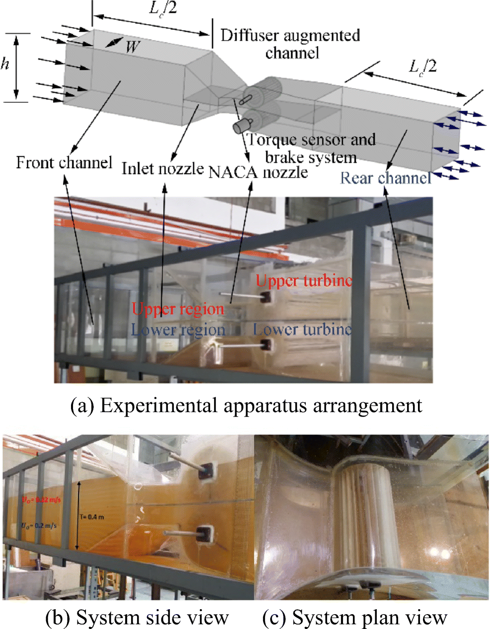 Figure 4 Schematic of present experimental apparatus. a Experimental apparatus arrangement
4.2 Measurement Apparatus
The test rig is aimed at deriving a prognosis for the CFTs during operation by determining the current water velocity, turbine speed, TSR, shaft torque, output power, and efficiency, as described in Eqs. (3)–(5). The result may reveal the relationship between the aforementioned parameters and thus help to find the flow field properties and performance characteristics of CFTs.
The efficiency (η) and power output (Po) of turbines were used to reflect turbine performance, as presented in Eqs. (3) and (4):
$$ {\rm{ \mathsf{ η} }} =\frac{P_o}{P_c} $$ (3) $$ {P}_o= T\omega $$ (4) where T is the output torque, ω represents the angular velocity of the runner, PC = 0.5ρAU03 represents the maximum hydrokinetic power that can be captured from the channel, ρ is the water density, (A) is the flow's cross-sectional area at the channel inlet, and U0 indicates the flow stream velocity. One should determine the effects of TSR on the efficiency of the turbine runner. TSR is the ratio of the peripheral velocity of the runner (U = ⍵r) to the inflow mean inlet runner speed (V), as defined in the following equation:
$$ \mathrm{TSR}=\frac{\omega r}{V} $$ (5) where r represents the turbine radius. TSR ranges from 0.1 to 2.2 for the lower and upper CFTs at a constant turbine radius of 0.1 m.
The test measurement apparatus, high-speed camera, digital torque sensor, and revolutions per minute (RPM) meters are necessary in effective test measurements. All sets of equipment used herein were calibrated, developed, and obtained within the UTM laboratory facilities.
The uncertainties of the experimental results in terms of the parameters, TSR, torque coefficient, and power coefficient were around 2.8%, 4%, and 4.5%, respectively.
4.2.1 High-Speed Camera
The velocity of the flow of water through the BDA system with turbines was measured by a high-speed camera (Figure 5a). The camera is a branded Phantom V710 megapixel camera that is capable of taking 1 400 000 pictures per second and features ultra-fast 7 Gpx/s throughput, 1280 × 800 at 7530 fps, 300 ns digital exposure, and compatibility with Phantom Cine Mag. The high-speed camera was used to record videos at the plane of the channel system from the side view (Figure 5b) for the measurement of the velocity variations along the BDA system. The high-speed camera adopts a particle-tracking method, in which small lighter rings are used as tracking particles. The videos recorded by the high-speed camera were then imported to Phantom Camera Control software to measure the velocities.
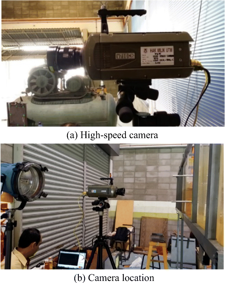 Figure 5 High-speed camera location and facilities
4.2.2 Torque Sensor
Futek TRS 605 torque meter was used to measure the turbine shaft torque and rotational speed. The torque sensors measured the torque with the aid of strain gauges, which were applied to the torsion section to prompt a change in impedance that depended on the torque. This change caused a voltage change that was proportional to the change in impedance and reached the evaluation instrument (IBT 100). Then, the torque and rotational speed (RPM) measured by the Futek sensor were imported to data acquisition software to find the values. The load was changed by the brake system, which controlled the rotational speed (RPM) of the turbine shaft.
5 Results and Discussion
The velocity measured lines obtained by the high-speed camera for the lower and upper regions were positioned at Y = 0.3, Z = 0.22, and Y = 0.3, Z = 0.3 (Figure 6).
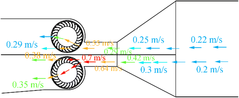 Figure 6 Velocity variations along the BDA channel and through CFT rotors at optimum TSR
The new concept of the BDA system is to use two directed nozzles in the microchannel to increase the flow velocity of water twice due to the enhancement of the extracted hydrokinetic power available for two turbines. Figure 6 shows the velocity value tracking for the lower and upper regions measured experimentally along a central plane through the BDA channel. The presented application could enhance the speed of fluid. In this study, the water velocity increased twice with the decrease of the area of contraction along the BDA system due to the presence of the two directed nozzles. The speed of the flow increased by 400%.
The velocity values for the lower and upper regions at the end of the first nozzle increased to 0.42 and 0.25 m/s, respectively. The free stream inlet velocities available for the lower and upper regions were 0.2 and 0.22 m/s, respectively. The velocity increased again at the end of the second NACA nozzle stage; the maximum inlet velocities of the lower and upper runners were 0.7 and 0.55 m/s, respectively. Consequently, the NACA nozzle significantly increased the water velocities by about 3.2 and 2.3 times relative to the system's free stream inlet velocity for the lower and upper regions, respectively. Then, the velocities behind the turbine started to decrease, dropping to nearly 0.35 and 0.29 m/s. The differences between the values of velocities in front and behind the turbines denoted the amount of kinetic energy extracted by the turbines.
The velocity values of the lower region were obviously greater than those of the upper region because the lower region occupied a larger water area than the upper part. Moreover, the crossed flow velocity through the lower turbine was greater than that through the upper runner because of the lower turbine being in normal mode and the effect of gravitational force. Thus, in this design, the output power and efficiency of the lower runner were expected to exceed those of the upper rotor.
Figure 7 shows the relation between the mean inlet runner velocity and the peripheral or circumferential velocity (ωr). The mean inlet runner velocity for the two turbines decreased with the increase of the peripheral velocity. Thus, the inlet flow of water passed quickly through the runner when the turbines rotated slowly.
 Figure 7 Variations of mean inlet runner velocities at different peripheral velocities for the lower and upper runners
Figure 8 shows the variations of the mean runner velocity and peripheral velocity with TSR. The mean inlet velocities of the two cases decreased with the increase of the TSR. Meanwhile, the TSR increased with the increment of circumferential velocity or the rotational speed (r/min). The inlet runner velocity for the lower rotor was greater than that for the upper turbine (Figures 7 and 8) because the upper region occupied 0.25 m of the inlet water level while water entered the upper part of the inlet nozzle at 0.15 m water depth. Furthermore, the lower part of the system was in normal mode; thus, the kinetic energy available to the upper turbine was lower than that in the lower region, and the rotational speed was projected to increase, as shown in Figure 8a. High-performance characteristics were also expected.
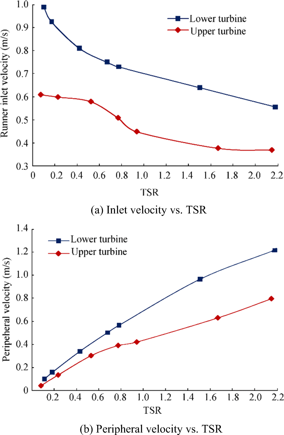 Figure 8 Variations of runner inlet and peripheral velocities with TSR for the upper and lower turbines
5.1 Performance Characteristics
Figure 9 displays the variations of the instantaneous output torques of the upper and lower turbines at various load conditions. The torque values were periodic and varied according to the changes in the rotational speed; that is, they increased with the decrease of rotational speed. The torque and rotational speed of the lower turbine were greater than those of the upper turbine because the flow rate available for the lower region was greater than that for the upper region. The load was changed by the brake system, which controlled the rotational speed of the turbine shaft.
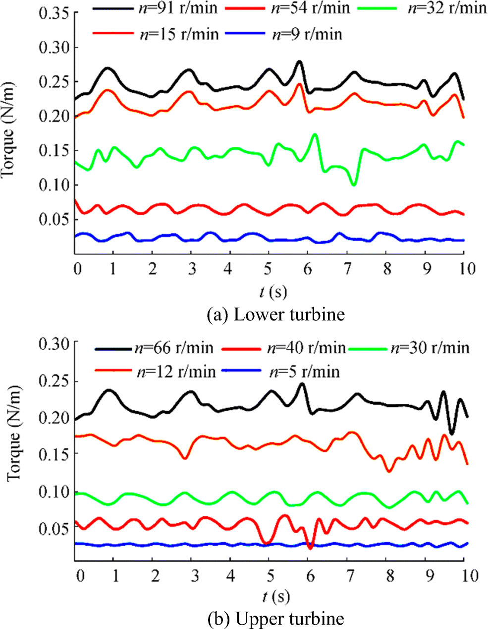 Figure 9 Historical timeline of output torque for lower and upper turbines at various loads
The historical timeline of the output torque and power of the lower and upper turbines at no load and at optimum load conditions is shown in Figure 10. The instantaneous torque and power of the turbines were cyclic with timeline, and the two outputs showed a direct relationship. The power and torque under the loaded condition were obviously higher than those under the no load case. At this loaded condition case, the increase of the load increased the flow resistance and, consequently, the pressure difference through the BDA system. Hence, the torque and power increased.
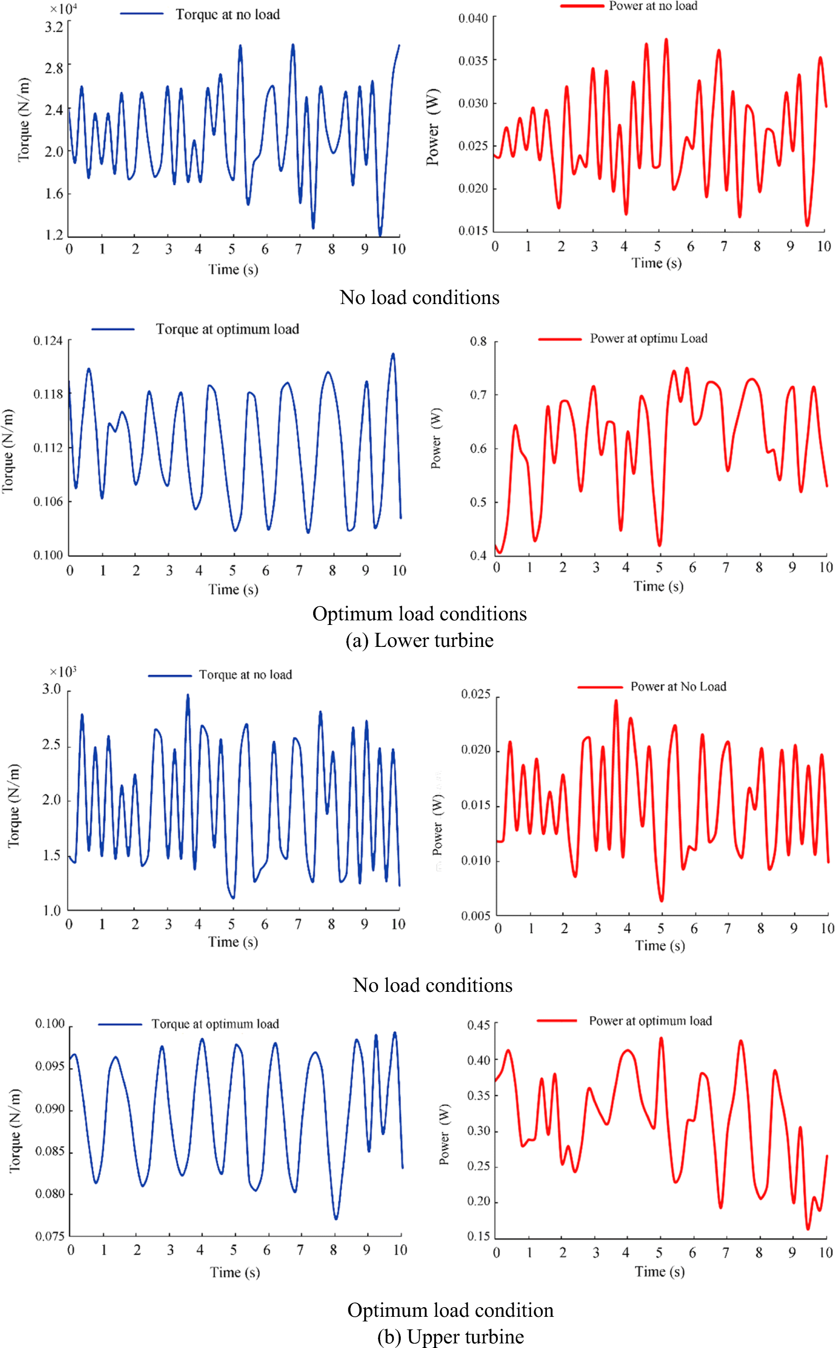 Figure 10 Historical timeline of output torque and power for the lower and upper turbines under no load and optimum load conditions
The two turbines were tested at various TSR and inlet runner flow rates. The performance characteristic curves of the two tested turbines are shown in Figures 11 and 12. The torque decreased with the increment of the TSR or with the increment of the rotational speed. By contrast, the torque considerably increased when the flow rate increased. The maximum average torque values indicated for the lower and upper turbines were about 0.228 and 0.18 N•m in the cases of the lower and upper turbines, respectively; they were recorded at the lowest TSR and rotational speed (RPM) values.
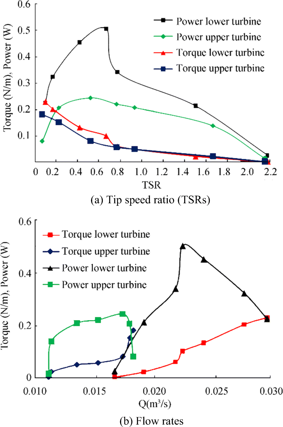 Figure 11 Output torque and power variations
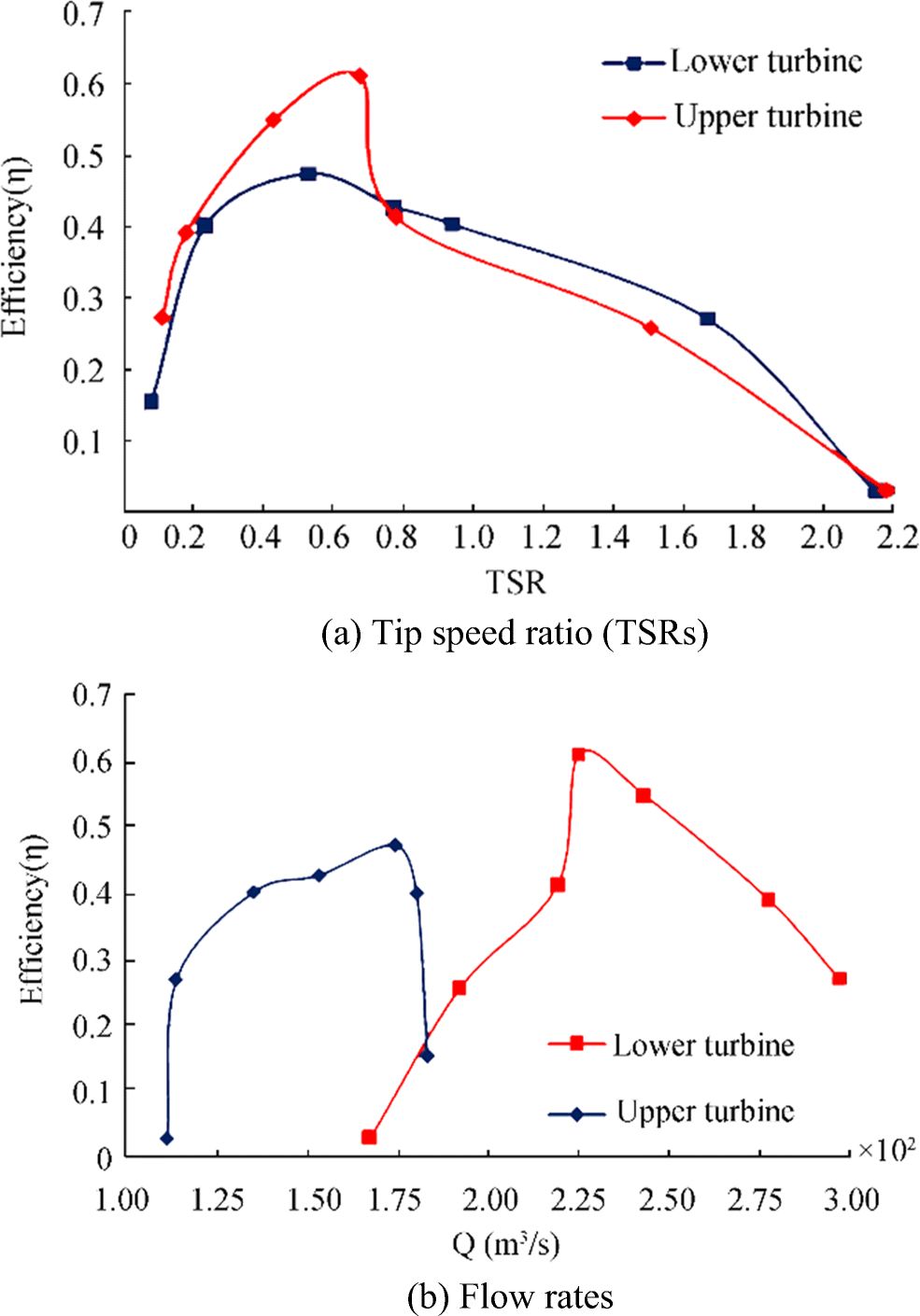 Figure 12 Efficiency variations
The output power increased with the increase of the TSR and inlet runner flow rate (Q) until it reached a peak value at the optimum values of TSR and Q; thereafter, it completely decreased. The optimum values of the TSR were nearly 0.66 and 0.52 for the lower and upper rotors, respectively; the optimum flow rates indicated for the lower and upper turbines were 0.0225 and 0.0174 m3/s, respectively. Moreover, the maximum power of the lower turbine was around 0.51 W, whereas that of the upper turbine was about 0.242 W. Although the torque values of the upper and lower turbines were close, the lower turbine's power output was higher than that of the upper turbine due to the higher values of circumferential velocity and RPM of the lower turbine (Figure 8b).
The efficiency curves of the lower and upper turbines curve showed the same trend for the output power curve (Figure 12). The highest efficiency of the current turbines tended to increase with the increase in the flow rate and TSR until it reached 61.2% and 47.3% for the lower and upper turbines, respectively; thereafter, the efficiency dropped. The best efficiency of the lower turbine was recorded at a high TSR, whereas that of the upper turbine was recorded at a low TSR mainly because of the lower rotational speed (RPM) values for the upper turbine than for the lower runner (Figures 7 and 8b). Furthermore, the ranges of the inlet flow rate available to the lower runner region were greater than those available to the upper runner because the lower part occupied a larger area of the inlet flow. In conclusion, the highest efficiency of the overall system with the two CFTs was 0.557.
6 Conclusions
1) This research focused on a newly configured nozzle system that included a novel arrangement of two Banki turbines/CFTs to harness power from rainy/irrigation microchannels existing in low-velocity regions.
2) A new system with bidirectional nozzles in two directions of a microchannel was developed. The system enhanced the flow velocity more than once before entry into the turbines. The new concept of utilizing the NACA shape as a built-in nozzle for channels was proposed, and its application improved the characteristics of channel flow. The speed of the flow increased by 400%.
3) Turbine operation and performance in the new channel arrangement were analyzed and evaluated. Experiments were conducted to determine the efficiencies of the turbines, which were found to be 61.2% and 47.3% for the lower and upper turbines, respectively.
4) This system promises more sufficient performance and higher efficiency than the conventional hydrokinetic turbines and CFT systems utilized in wave and tidal power generation schemes.
Acknowledgments: The authors would like to express their sincere gratitude to Universiti Teknologi Malaysia (UTM) for providing assistance and access to data and experimental apparatus for this publication. -
Figure 1 Schematics of augmented diffuser configuration, including cross flow turbine runners
Figure 2 Final design of CFT runner
Figure 3 Flow directions and velocity triangles of the two stages through the turbines
Figure 4 Schematic of present experimental apparatus. a Experimental apparatus arrangement
Figure 5 High-speed camera location and facilities
Figure 6 Velocity variations along the BDA channel and through CFT rotors at optimum TSR
Figure 7 Variations of mean inlet runner velocities at different peripheral velocities for the lower and upper runners
Figure 8 Variations of runner inlet and peripheral velocities with TSR for the upper and lower turbines
Figure 9 Historical timeline of output torque for lower and upper turbines at various loads
Figure 10 Historical timeline of output torque and power for the lower and upper turbines under no load and optimum load conditions
Figure 11 Output torque and power variations
Figure 12 Efficiency variations
-
Adhau SP, Moharil RM, Adhau PG (2012) Mini-hydro power generation on existing irrigation projects: case study of Indian sites. Renew Sust Energ Rev 16: 4785–4795. https://doi.org/10.1016/j.rser.2012.03.066 Andrade D, Jesús CC, Kenyery F, Aguillón O, Vásquez A, Asuaje M (2011) Numerical investigation of the internal flow in a Banki turbine. Int J Rotating Mach 11: Article ID 841214, 12 pages. https://doi.org/10.1155/2011/841214 Arkel VR, Owen J, Allison S, Tryfonas T, Winter A, Entwistle R (2011) Design and preliminary testing of a novel concept low depth hydropower device. OCEANS'11 MTS/IEEE KONA, Waikoloa, 2011, pp 1–10. https://doi.org/10.23919/OCEANS.2011.6107051 Bryden I, Melville G (2004) Choosing and evaluating sites for tidal current development. In: Proceedings of the institution of mechanical engineers, vol. 218, Part A: Journal of Power and Energy. Professional Engineering Publishing Limited, London, ISSN: 0957-6509, 567–577. https://doi.org/10.1243/0957650042584375 Bryden I, Scott JC (2007) How much energy can be extracted from moving water with a free surface: a question of importance in the field of tidal current energy? Renew Energy 32(11): 1961–1966. https://doi.org/10.1016/j.renene.2006.11.006 Butera I, Balestra R (2015) Estimation of the hydropower potential of irrigation networks. Renew Sust Energ Rev 48: 140–151. https://doi.org/10.1016/j.rser.2015.03.046 Choi Y-D, Lim J-I, Kim Y-T, Lee Y-H (2008) Performance and internal flow characteristics of a cross-flow hydro turbine by the shapes of nozzle and runner blade. J Fluid Sci Technol 3(3): 398–409. https://doi.org/10.1299/jfst.3.398 Choi Y-D, Kim C-G, Lee Y-H (2009) Effect of wave conditions on the performance and internal flow of a direct drive turbine. J Mech Sci Technol 23(6): 1693–1701. https://doi.org/10.1007/s12206-009-0414-4 Choi Y-D, Kim C-G, Kim Y-T, Song J-I, Lee Y-H (2010) A performance study on a direct drive hydro turbine for wave energy converter. J Mech Sci Technol 24(11): 2197–2206. https://doi.org/10.1007/s12206-010-0903-5 Desai VR, Aziz NM (1994) Parametric evaluation of cross-flow turbine performance. J Energy Eng 120(1): 17–34. https://doi.org/10.1061/(ASCE)0733-9402(1994)120:1(17) Draper S, Adcock TAA, Borthwick AGL, Houlsby GT (2014) Estimate of the tidal stream power resource of the Pentland Firth. Renew Energy 63: 650–657. https://doi.org/10.1016/j.renene.2013.10.015 Elbatran AH, Abdel-Hamed MW, Yaakob OB, Ahmed YM (2015a) Hydro power and turbine systems reviews. J Teknol 74(5): 83–90. https://doi.org/10.11113/jt.v74.4646 Elbatran AH, Yaakob OB, Ahmed YM, Shabara HM (2015b) Operation, performance and economic analysis of low head micro-hydropower turbines for rural and remote areas: a review. Renew Sust Energ Rev 43: 40–50. https://doi.org/10.1016/j.rser.2014.11.045 Elbatran AH, Yaakob OB, Ahmed YM, Shabara HM (2015c) Numerical investigation of curvature and torsion effects on water flow field in helical rectangular channels. J Eng Sci Technol 10(7): 827–840 http://jestec.taylors.edu.my/Vol10issue7July2015/Volume(10)Issue(7)827-840.pdf Elbatran AH, Yaakob OB, Ahmed YM, Shabara HM (2015d) Numerical study for the use of different nozzle shapes in microscale channels for producing clean energy. Int J Energy Environ Eng 6(2): 137–146. https://doi.org/10.1007/s40095-014-0158-5 Elbatran AH, Yaakob OB, Ahmed YM, Jalal MR (2015e) Novel approach of bidirectional diffuser-augmented channels system for enhancing hydrokinetic power generation in channels. Renew Energy 83: 809–819. https://doi.org/10.1016/j.renene.2015.05.038 Elbatran AH, Yaakob OB, Ahmed YM, Abdallah F (2016) Augmented diffuser for horizontal axis marine current turbine. Int J Power Electron Drive Syst 7(1): 235–245. https://doi.org/10.11591/ijpeds.v7.i1.pp235-245 Elbatran AH, Ahmed YM, Shehata AS (2017) Performance study of ducted nozzle Savonius water turbine, comparison with conventional Savonius turbine. Energy 134: 566–584. https://doi.org/10.1016/j.energy.2017.06.041 Elbatran AH, Yaakob OB, Ahmed YM, Shehata AS (2018) Numerical and experimental investigations on efficient design and performance of hydrokinetic Banki cross flow turbine for rural areas. Ocean Eng 159: 437–456. https://doi.org/10.1016/j.oceaneng.2018.04.042 Fiuzat AA, Akerkar BP (1991) Power outputs of two stages of cross-flow turbine. J Energy Eng 117(2): 57–70. https://doi.org/10.1061/(ASCE)0733-9402(1991)117:2(57) Garrett C, Cummins P (2007) The efficiency of a turbine in a tidal channel. J Fluid Mech 588: 243–251. https://doi.org/10.1017/S0022112007007781 Goude A, Ågren O (2014) Simulations of a vertical axis turbine in a channel. Renew Energy 63: 477–485. https://doi.org/10.1016/j.renene.2013.09.038 Kaunda CS, Kimambo CZ, Nielsen TK (2014a) A numerical investigation of flow profile and performance of a low cost Crossflow turbine. Int J Energy Environ 5(3): 275–296 https://www.ijee.ieefoundation.org/vol5/issue3/IJEE_01_v5n3.pdf Kaunda CS, Kimambo CZ, Nielsen TK (2014b) Experimental study on a simplified cross flow turbine. Int J Energy Environ 5(2): 155–182 https://www.ijee.ieefoundation.org/vol5/issue2/IJEE_02_v5n2.pdf Khan AA, Khan AM, Zahid M, Rizwan R (2013) Flow acceleration by converging nozzles for power generation in existing canal system. Renew Energy 60: 548–552. https://doi.org/10.1016/j.renene.2013.06.005 Khosrowpanah S, Fiuzat AA, Albertson ML (1988) Experimental study of cross-flow turbine. J Hydraul Eng 114(3): 299–314. https://doi.org/10.1061/(ASCE)0733-9429(1988)114:3(299) Kim K-P, Ahmed R, Lee Y-H (2012) Efficiency improvement of a tidal current turbine utilizing a larger area of channel. Renew Energy 48: 557–564. https://doi.org/10.1016/j.renene.2012.06.018 Kim B-H, Wata J, Zullah MA, Rafiuddin Ahmed M, Lee Y-H (2015) Numerical and experimental studies on the PTO system of a novel floating wave energy converter. Renew Energy 79: 111–121. https://doi.org/10.1016/j.renene.2014.11.029 Kokubu K, Kanemoto T, Yamasaki K (2013) Guide vane with current plate to improve efficiency of cross flow turbine. Open J Fluid Dyn 3(2): 28–35. https://doi.org/10.4236/ojfd.2013.32A005 Mockmore CA, Merryfield F (1949) The Banki water turbine. In: Bullettin Series, Engineering Experiment Station; Oregon State System of Higher Education, Oregon State College: Corvallis. http://hdl.handle.net/1957/32305 Nakase Y, Fukutomi J, Watanabe T, Suetsugu T, Kubota T, Kushimoto S (1982) A study of cross-flow turbine (effects of nozzle shape on its performance). In: Small Hydro Power Fluid Machinery (Proc. the Winter Annual Meeting of the American Society of Mechanical Engineers), Phoenix, Arizona, USA, 13. https://ci.nii.ac.jp/naid/10004536280/#cit Okot D (2013) Review of small hydropower technology. Renew Sust Energ Rev 26: 515–520. https://doi.org/10.1016/j.rser.2013.05.006 Olgun H (1998) Investigation of the performance of a cross flow turbine. Int J Energy Res 22: 953–964. https://doi.org/10.1002/(SICI)1099-114X(199809)22:11<953::AID-ER418>3.0.CO;2-1 Prasad DD, Rafiuddin Ahmed M, Lee Y-H (2014) Flow and performance characteristics of a direct drive turbine for wave power generation. Ocean Eng 81: 39–49. https://doi.org/10.1016/j.oceaneng.2014.02.019 Rojanamon P, Chaisomphob T, Bureekul T (2009) Application of geographical information system to site selection of small run-of-river hydropower project by considering engineering/economic/ environmental criteria and social impact. Renew Sust Energ Rev 13(9): 2336–2348. https://doi.org/10.1016/j.rser.2009.07.003 Sammartano V, Aricò C, Carravetta A, Fecarotta O, Tucciarelli T (2013) Banki-Michell optimal design by computational fluid dynamics testing and hydrodynamic analysis. Energies 6(5): 2362–2385. https://doi.org/10.3390/en6052362 Shabara H, Yaakob O, Ahmed Y, Elbatran A (2015a) CFD simulation of water gravitation vortex pool flow for mini hydropower plants. J Teknol 74(5): 77–81. https://doi.org/10.11113/jt.v74.4645 Shabara HM, Yaakob OB, Ahmed YM, Elbatran AH, Faddir MSM (2015b) CFD validation for efficient gravitational vortex pool system. J Teknol 74(5): 97–100. https://doi.org/10.11113/jt.v74.4648 Shimokawa K, Furukawa A, Okuma K, Matsushita D, Watanabe S (2012) Experimental study on simplification of Darrieus-type hydro turbine with inlet nozzle for extra-low head hydropower utilization. Renew Energy 41: 376–382. https://doi.org/10.1016/j.renene.2011.09.017 Totapally, Hara GS, Aziz NM (1994) Refinement of cross-flow turbine design parameters. J Energy Eng 120(3): 133 Vennell R (2011) Estimating the power potential of tidal currents and the impact of power extraction on flow speeds. Renew Energy 36(12): 3558–3565. https://doi.org/10.1016/j.renene.2011.05.011 Vennell R (2012a) Realizing the potential of tidal currents and the efficiency of turbine farms in a channel. Renew Energy 47:95–102. https://doi.org/10.1016/j.renene.2012.03.036 Vennell R (2012b) The energetics of large tidal turbine arrays. Renew Energy 48:210–219. https://doi.org/10.1016/j.renene.2012.04.018 Vennell R (2013) Exceeding the Betz limit with tidal turbines. Renew Energy 55:277–285. https://doi.org/10.1016/j.renene.2012.12.016 Vermaak HJ, Kusakana K, Koko SP (2014) Status of micro-hydrokinetic river technology in rural applications: a review of literature. Renew Sust Energ Rev 29:625–633. https://doi.org/10.1016/j.rser.2013.08.066 Walseth EC (2009) Investigation of the flow through the runner of a cross-flow turbine, Master of Science in Product Design and Manufacturing, Norwegian University of Science and Technology, Department of Energy and Process Engineering, 2009. http://hdl.handle.net/11250/233689 Zema DA, Nicotra A, Tamburino V, Zimbone SM (2016) A simple method to evaluate the technical and economic feasibility of micro hydro power plants in existing irrigation systems. Renew Energy 85:498–506. https://doi.org/10.1016/j.renene.2015.06.066